— ACS1000 air-cooled The flexibility you require. The reliability you expect. Document name ACS1000 air-cooled user manual Document owner ABB Switzerland Ltd. Medium voltage AC drives Document number 3BHS213401 E01 Rev H Number of pages 184 Release date 2020-03-18 — new.abb.com/drives/medium-voltage-ac-drives
1.1 Copyright notice The information in this manual is subject to change without notice. This manual and parts thereof must not be reproduced or copied, or disclosed to third parties, nor used for any unauthorized purpose without written permission from ABB Switzerland Ltd., Medium Voltage Drives. The hardware and software described in this manual is provided under a license and may be used, copied, or disclosed only in accordance with the terms of such license.
1.2 Equipment covered by this manual This manual covers a standard drive and provides generic information on the drive. The manual does not claim to cover all variations and details of the drive, nor to consider all eventualities that may arise during installation, commissioning, operation and maintenance of the drive. If the drive is adapted to specific customer needs or applications, and handling, installation and operation of the drive are affected by these modifications, information on these modifications is provided in the appropriate documentation (eg, layout drawings, wiring diagrams, technical data, engineering notes). If information is required beyond the instructions in this manual, refer the matter to ABB.
1.3 Structure of the user documentation The complete set of user documentation of a standard drive consists of this manual and supplementary documentation that is provided in the following appendices: – Appendix A – Additional manuals Appendix A provides manuals about additional equipment delivered with the drive (such as project-specific options such as pulse encoder or fieldbus interfaces), or information on modifications of the standard drive. – Appendix B – Technical data Appendix B contains the technical data sheets of the drive. – Appendix C – Mechanical drawings Appendix C provides the outline drawings of the drive. The drawings are generated according to the customer-specific project. – Appendix D – Wiring diagrams • Appendix D contains the circuit diagrams with information on device identification, cross-reference and device identification conventions. The diagrams are generated according to the customer-specific project. • “Setting of protective devices” is generated according to the customer-specific project. – Appendix E – Parts list The parts list is produced for each project and contains all information to identify a component. – Appendix F – Test reports and certificates Appendix F provides the test reports of the drive. Quality certificates, and codes and standards the drive complies with are added if necessary for the project.
– Appendix G – Signal and parameter table The Signal and parameter table includes descriptions of actual signals, control and status words, and control parameters and their default settings.
Terms and abbreviations The following table lists terms and abbreviations you should be familiar with when using this user manual. Some of the terms and abbreviations used in this user manual are unique to ABB and might differ from the normal usage.
Term/Abbreviation Definition
ACS1000A ACS1000 air-cooled drive AMC circuit board Application and Motor Controller The digital signal processor is the heart of the control system of the drive. Cluster A cluster is a synonym for a group of hardware modules of the drive control system. DDCS Distributed drive control system DDCS is an acronym for a serial communication protocol designed for data transfer via optical fibers. Drive Short form for ACS1000 drive Drive system The drive system includes all equipment used to convert electrical into mechanical power to give motion to the machine. DriveBus Communication link dedicated for ABB drives DriveDebug DriveDebug is part of ABB’s DriveWare® software tools for drives using the DDCS communications protocol. DriveDebug runs on computers with Windows® operating systems. DriveDebug is a specialist’s tool used to diagnose, tune and troubleshoot ABB drives. DriveWindow DriveWindow is a DriveWare® product. DriveWindow is a 32 bit Windows® application for commissioning and maintaining ABB drives equipped with optical communication links. Equipment Frequency converter and related equipment EMC Electromagnetic compatibility All measures to suppress electromagnetic disturbances caused by different electrical equipment in the same electromagnetic environment, and to strengthen the immunity of the equipment to such disturbances. Ground Earth To ground The conducting path (eg, conductor) between the electric equipment (eg, frequency converter) and the earth. The electric equipment is connected to the earth, eg, by a grounding set or a grounding switch. INU Inverter unit of the drive. The INU converts the DC voltage to the required AC motor voltage and frequency. IOEC module The IOEC module is an active input and output device for digital and analog signals. Line voltage RMS voltage of the main power supply of the drive MCB Main circuit breaker The MCB is a major protection device of the drive and is the main connection and disconnection point between the main power supply and the drive. Molykote Brand name for lubricants PCB Printed circuit board
Term/Abbreviation Definition
PCC Point of common coupling The PCC is the point in the electrical power supply system where the responsibility of the utility changes to the industrial customer. The utility is responsible to provide clean voltage and current with respect to harmonic distortion up to the PCC. The industrial customer is responsible not to distort voltage and current by its electrical systems. PID controller Proportional-integral-derivative controller Control loop feedback system for controlling process variables (eg, pressure, flow) PE Protective earth PPCS Power plate communication system PPCS is an acronym for a serial communication protocol designed for data transfer via optical fibers between AMC circuit board and INTerface circuit boards. RTD Resistance temperature detector or device The RTD is a temperature sensor where the change in electrical resistance is used to measure the temperature. Supervisory signal Indicates the operating condition of a circuit or device. SW Software TC Short form for terminal compartment of the drive UPS Uninterruptible power supply Zero speed threshold Used in the manual to indicate that the drive has reached the value “zero speed” that is set in a parameter. The value can be set in the range of 0 and maximum speed (the unit for the speed is rpm).
Trademarks Names that are believed to be trademarks of other companies and organizations are designated as such. The absence or presence of such a designation should however not be regarded as an offense of the legal status of any trademark. The following registrations and trademarks are used in this manual:Trademark Definition Windows® Registered trademark of Microsoft Corporation Industrial IT™ Trademark of ABB DriveWare® Registered trademark of ABB Ethernet® Registered trademark of Xerox Corporation Profibus® Registered trademark of Profibus International (P.I.) Modbus® Registered trademark of the Modbus IDA organization Molykote® Registered trademark of Molykote
1.8 User’s responsibilities It is the responsibility of those in charge of the drive to ensure that each person involved in the installation, operation or maintenance of the drive has received the appropriate training and has thoroughly read and clearly understood the instructions in this manual and the relevant safety instructions.
1.9 Intended use of equipment Those in charge of the drive must ensure that the drive is only used as specified in the contractual documents, operated under the conditions stipulated in the technical specifications and on the rating plate of the drive, and serviced in the intervals specified by ABB. Use of the drive outside the scope of the specifications is not permitted. Intended equipment use also implies that only spare parts recommended and approved by ABB must be used. Unauthorized modifications and constructional changes of the drive are not permitted.
1.10 Cyber security disclaimer This product is designed to be connected to and to communicate information and data via a network interface. It is the customer’s sole responsibility to provide and continuously ensure a secure connection between the product and Customer network or any other network (as the case may be). Customer shall establish and maintain any appropriate measures (such as but not limited to the installation of firewalls, application of authentication measures, encryption of data, installation of anti-virus programs, etc) to protect the product, the network, its system and the interface against any kind of security breaches, unauthorized access, interference, intrusion, leakage and/or theft of data or information. ABB and its affiliates are not liable for damages and/or losses related to such security breaches, any unauthorized access, interference, intrusion, leakage and/or theft of data or information
1.11 Quality certificates and applicable standards The following certificates and conformity declarations are available with ABB: – ISO 9001 and ISO 14001 certificates stating that ABB Switzerland Ltd has implemented and maintains a management system which fulfills the requirements of the normative standards – EC declaration of conformity – List of standards the drive complies wit
16] ANSI Z535.6 American national standard for product safety information in product manuals, instructions, and other collateral materials [17] ISO 3864-2:2004 (E) – Graphical symbols – Safety colors and safety signs – Part 2: Design principles for product safety labels [18] ISO 7010:2011 (E) – Graphical symbols – Safety colours and safety signs – Registered safety sign [19] EN 50110 European standard code for electrical work safety [20] ISO 13849-1 Safety of machinery – Safety-related parts of control systems – Part 1: General principles for design, section 6.2.6 Category 3 [21] IEC 60204-1 Safety of machinery – Electrical equipment of machines – Part 1: General requirements [22] IEC 60721-3-1 Classification of environmental conditions: Classification of groups of environmental parameters and their severities; Storage [23] IEC 60721-3-2 Classification of environmental conditions – Part 3-2: Classification of groups of environmental parameters and their severities – Transportation and Handling [24] IEC 60721-3-3 Classification of environmental conditions – Part 3: Classification of groups of environmental parameters and their severities – Section 3: Stationary use at weatherprotected location [25] IEC 62477-2 Safety requirements for power electronic converter systems and equipment – Part 2: Power electronic converters from 1 000 V AC or 1 500 V DC up to 36 kV AC or 54 kV DC
1.12 Items covered by delivery Delivery typically comprises the following items: – Drive that is shipped in sea freight or airfreight packaging. – Optional components and cabinets – Set of door keys attached to lifting rail (1 in Fig. 1-1) – Set of door keys inside the drive – Rating label (2 in Fig. 1-1) – Box with USB stick (3 in Fig. 1-1), which contains the user manual and related documents. – Strain relief rails – Air exhaust hood – Redundant fan unit (option) – Set of bolts, nuts and washers
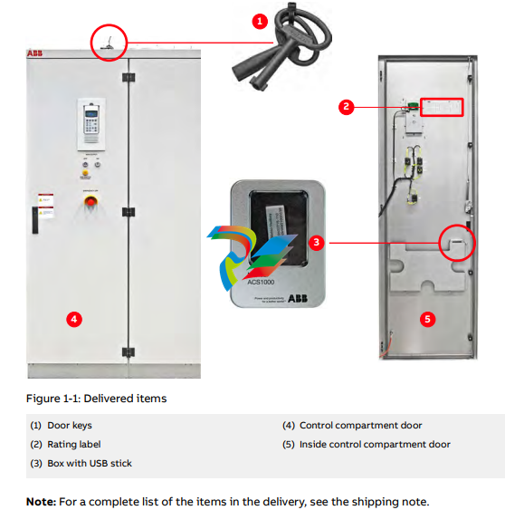
1.13 Identifying the delivery The drive and accessories are identified by the type code printed on the rating label. The label provides information on the type of drive, the rated voltage, the frequency and the current of the main and the auxiliary power supply
2.1 Overview Read this material before working on or around the equipment. Failure to do so can result in injury or death!
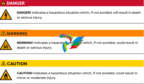
2.1.1 Safety standards The following industry standards are observed: – “ANSI Z535.6 American national standard for product safety information in product manuals, instructions, and other collateral materials” [16] – “ISO 3864-2:2004 (E) – Graphical symbols – Safety colors and safety signs – Part 2: Design principles for product safety labels” [17] – “ISO 7010:2011 (E) – Graphical symbols – Safety colours and safety signs – Registered safety sign” [18] – “EN 50110 European standard code for electrical work safety” [19] 2.2 Safety messages The following safety messages are provided to help prevent personal injury and damage to the equipment. The indicated hazard level is based on the ANSI Z535.6 standard.
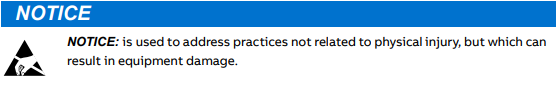
Damage prevention information
Product safety labels Safety labels are affixed to the drive components to alert personnel of potential hazards when working on the equipment. For more information, see the label placement document for the drive. The instructions on the safety labels must always be followed and the labels must be kept in a perfectly legible condition.
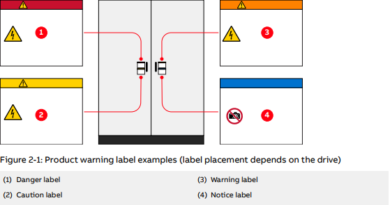
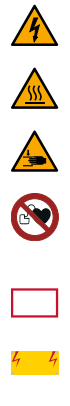
Additional safety labels, including the following, might also be provided: (1) Danger label (2) Caution label (3) Warning label (4) Notice label Electricity hazard This sign can also have additional text below it, eg, “High voltage” Hot surface Crushing of hands No access for people with active implanted cardiac device The magnetic field of the drive can influence the functioning of pacemakers. The pacemaker sign should be installed at the entrance to the drive room or at a minimum distance of 6 m from the drive to stop personnel with pacemakers approaching the drive. Firefighting sign Outlines the procedure when fighting fire in electrical equipment. The sign must be installed well visible near the drive. High voltage sign Must be installed clearly visible at the main circuit breaker in the switchgear room. The sign alerts personnel to the high voltage which can be present on the secondary side of the input transformer until the main circuit breaker has been opened and secured and the drive has been de-energized and grounded.
Leave a comment
Your email address will not be published. Required fields are marked *