Decreases capital equipment costs
Decreases installation time and expense
Increases productivity
Increases process availability
Introduction
Traditional I/O is a modular subsystem that offers flexibility
during installation. It’s designed to be installed in the field,
near your devices. Traditional I/O is equipped with function
and field wiring protection keys to ensure that the correct
I/O card is always plugged into the corresponding terminal
block. Modularity, protection keys, and plug and play
capabilities make DeltaV™ Traditional I/O a smart choice
for your process control system.
Benefits
Decreases capital equipment costs
Full system modularity. The Traditional I/O
subsystem was designed with your investment in mind. All
components are fully modular and may be installable
under power.1 You add I/O interface carriers and I/O
interfaces in groups of 4, 8, 16, or 32 channels as you
need them. The modular design enables you to purchase
the exact amount of I/O cards, 8-wide carriers,
power/controllers, and 2-wide carriers you need and add
more DeltaV I/O as your system grows.
Reduced system footprint. The DeltaV system’s
state-of-the-art form factor design of the I/O components
enables you to mount the I/O interface carrier in a junction
box in the field so you significantly reduce the footprint of
your equipment and increase valuable control room space
for other uses.
Installation. Save on wiring expenses by installing
Classic Instrumentation in the field, near the actual field
devices. Mounting the controller with the I/O further
reduces your wiring expenditures by eliminating the need
for long runs of multi-cores. The integrated design of the
Traditional I/O subsystem can eliminate the need for
marshaling panels. This saves you even more in your total
capital costs.
The provision of in-line fuses and bussed power saves on
installation costs compared with external fuses and power
distribution.
Decreases installation time and expense
Plug-and-play installation saves money. All
Traditional I/O components plug into the I/O interface
carrier. You can install the I/O interface carriers to manage
anticipated growth and postpone the I/O interfaces until
you’re ready to install your additional field devices.
Phased installation saves time. As soon as you
mount the I/O interface carrier, you’re ready to begin
installing the field devices. I/O terminal blocks plug directly
onto the I/O interface carrier. There is no need to have the
I/O cards installed.
1 Refer to Zone 2 installation instructions (12P2046) and/or
Class 1 Division 2 installation instructions (12P1293) for
details.
Traditional I/O terminal block.
Keys. Traditional I/O interfaces and terminal blocks have
I/O function keys. These keys ensure that the correct I/O
card is always plugged into the corresponding terminal
block. It’s incredibly easy to use and gives you time to do
more.
This design enables you to initially install Traditional I/O
quickly and efficiently. When you need to replace an I/O
card, the function key design ensures that you will always
install it correctly. This keying system provides a safety
measure by preventing the wrong I/O interface’s being
installed.
Increases productivity
Real-time, online equipment additions. Online
addition of new I/O interfaces means your process does
not get interrupted. As new equipment is added, the
DeltaV Explorer acknowledges it and assigns it basic
configuration.
Increases process availability
1:1 Redundancy for Traditional and HART I/O
cards. DeltaV redundant I/O uses the same Series 2 I/O
cards as non-redundant I/O. This allows you to leverage
your investment in installed I/O and in I/O spares. No
additional configuration is needed when using a redundant
channel. The redundant terminal blocks provide the same
field wiring connections as simplex blocks, so there is no
extra wiring needed.
Autosense of redundancy. DeltaV autosenses
redundant I/O, which greatly simplifies the task of adding
redundancy to the system. The redundant pair of cards is
treated as one card in the system tools.
Automatic Switchover. Should a primary I/O card fail,
the system automatically switches to the “standby” card
without user intervention. The operator is given clear
notification of a switchover at the operator display
Product Description
The Traditional I/O subsystem includes:
I/O interface carrier (a DIN rail surface mounted) on
which all I/O related components are installed.
Bulk AC to 24 VDC power supply for field devices.
An I/O interface consisting of an I/O card and an I/O
terminal block.
A variety of analog and discrete I/O cards enclosed in
a common form factor that easily plugs into the I/O
interface carrier.
A variety of I/O terminal blocks mounted on the I/O
interface carrier that can be pre-wired before I/O card
installation.
A Traditional I/O card easily plugs into an I/O carrier
I/O Cards
A variety of analog and discrete I/O cards are available to
meet your specific requirements. The following cards
support simplex or redundant installation:
AI 4-20 mA HART 8 channels
AO-4-20 mA HART 8 channels
DI, 24 VDC Dry Contact, 8-channels
DO 24 VDC High Side, 8-channels
The following I/O cards are supported in simplex format to
meet your field wiring needs.
AI 4-20 mA HART 16 channels
AI Isolated, 4 channels
RTD, 8-channels
Thermocouple, 8- channels
Millivolt, 8-channels
DI, High Density, 32-channels
DI 24 VDC Isolated, 8-channels
Multi-Function, 4 channels (Isolated DI)
Sequence of Event, 16 channels (DI 24 VDC)
DI 120 VAC Low Side Detection, 8-channels
DI 120 VAC Isolated , 8-channels
DO, High Density, 32-channels
DO 24 VDC Isolated, 8-channels
DO 120/230 VAC High Side, 8 channels
DO 120/230 Isolated, 8 channels
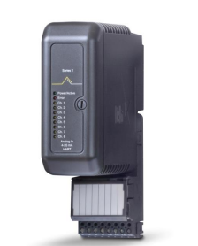
All I/O cards are enclosed in a common form factor that
plugs into the I/O interface carrier. The housing is clearly
labeled with the enclosed I/O card type. All cards have
power and internal error indicators. Eight channel cards
have clearly visible channel status LEDs.
All cards meet ISA G3 corrosion specifications by the
careful selection of superior electronic components and
the use of conformal coating.
Pulse Counters are available on most DI cards. The
supported maximum frequency varies from 0.1 Hz on AC
signals to 75 or 120 Hz on 24 VDC inputs. For higher
pulse counts up to 50 KHz, use the Multi-Function card’s
high speed pulse input.
DeltaV provides control module level time stamping for log
events and alarms. For greater event resolution the 16
channel Sequence of Events DI card can provide signal
driven events to a resolution of +/- 0.25 ms per card, or
within 1 ms per controller. Please refer to the Sequence
of Events PDS for more information on Sequence of Event
data collection and system options for this feature.
I/O Card Redundancy
Redundant I/O cards are available for critical applications.
The same card can be used in simplex or redundant
applications. When installed on a two-wide redundant
terminal block, the cards are recognized as a redundant
pair by the controller. The controller scans each card and
determines which card is acting as the active interface.
When a fault is detected, the system automatically
switches to the standby I/O card.
DeltaV Control modules reference simplex and redundant
I/O channels identically and there is no special
configuration required to take advantage of redundancy.
Switchover of a redundant I/O card is completed within
two scans of the I/O bus. Make-before-break contacts
ensure digital field instruments remain powered and the
process is undisturbed. Analog output signals are briefly
driven by both cards for < 5 ms during switchover of the
card.
Hardware Alerts automatically report hardware integrity
errors for both the primary and secondary cards. Any
event that causes a switchover is also reported
automatically through the system hardware alerts and is
logged in the Event Chronicle.
Events that can cause a switchover include.
Hardware failure within the active card.
Communications failure between the active card and
the controller.
Detection of a fault in the field wiring
A switchover may also be initiated from the diagnostics
explorer, and the health and status of both cards and their
channels are available in the diagnostics explorer.
The system automatically commissions a new standby
card. In safe areas, failed cards can be replaced under
power. In hazardous areas, appropriate installation
procedures must be followed.
Fused 8-Channel Terminal Block
AI 8-Channel Terminal Block
AI 16-channel Terminal Block
4-wire AI 16-channel Terminal Block
Discrete 32-Channel Terminal Block
Isolated Input Terminal Block
RTD/Resistance Terminal Block
Thermocouple Terminal Block
The following redundant I/O terminal blocks are available
on some I/O interfaces, allowing a pair of cards to be
installed as a redundant pair.
Redundant AI 8-Channel Terminal Block
Redundant AO 8-Channel Terminal Block
Redundant Discrete 8-Channel Terminal Block
The table on the following page lists the compatible
terminal blocks for each card, along with the cards unique
key positions. The first terminal block listed is the
recommended terminal block.
In addition to standard signal wiring, some cards may also
be ordered with Mass Termination blocks that allow these
cards to be connected to M-Series Mass Connection
Solution or to third party wiring solution, mounted in an
adjacent cabinet in order to meet special signal
conditioning or for optimizing field wiring solutions. Please
refer to the PDS M-series Mass Connection Solution or to
the Alliance Program website for details on approved 3rd
party products.
10-pin Mass Termination Block
16-pin Mass Termination Block
24-pin Mass Termination Block
40-pin Mass Termination Block
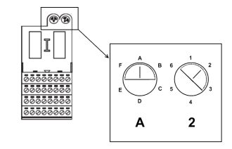
The keying mechanism consists of two keying posts that
rotate and lock into the terminal block base. Each post
has 6 positions: A-F and 1-6. Each card is assigned a
unique key which is marked on the side of the I/O card:
Terminal Block keying example
The keys prevent installation of an incorrect card, and the
graphical information on the card makes it easy to
determine if a keyed slot will accept a particular card.
There are 8 different I/O terminal blocks available to meet
the wiring needs of field signals.
8-Channel Terminal Block
Leave a comment
Your email address will not be published. Required fields are marked *