KEY FEATURES AND BENEFITS
• From the vibro-meter® product line
• 19″ system racks with a standard height of 6U
• Robust aluminium construction
• Modular concept allows specific cards to be
added for machinery protection and/or
condition monitoring
• Cabinet or panel mounting
• Backplane supporting the VME bus, the
VM600Mk2/VM600 system’s Tacho, Raw and
Open collector (OC) buses, and power supply
distribution
• Uses the VM600Mk2/VM600 RPS6U rack power
supply: AC and/or DC input versions
• Power supply check relay
APPLICATIONS
• VM600Mk2/VM600 machinery protection and/
or condition monitoring systems
DESCRIPTION
The VM600Mk2/VM600 ABE040 and ABE042 system
racks are used to house hardware for the
VM600Mk2/VM600 series of machinery protection
and/or condition monitoring systems, from
Meggitt’s vibro-meter® product line.
Two types of VM600Mk2/VM600 ABE04x system
rack are available: the ABE040 and the ABE042.
These are very similar, differing only in the position
of the mounting brackets. Both racks have a
standard height of 6U and provide mounting
space (rack slots) for up to 12 single-width
VM600Mk2/VM600 modules (card pairs), or a
combination of single-width and multiple-width
modules (cards). These racks are particularly
suitable for industrial environments, where
equipment must be permanently installed in 19″
cabinets or panels.
DESCRIPTION (continued)
The different versions of ABE04x system rack
enable different mounting options to support
various markets and applications.
The VM600 system rack has an integrated VME
backplane which provides the electrical
interconnections between the installed
VM600Mk2/VM600 modules (cards): power supply,
signal processing, input /output, relay and
CPUx “rack controller”. It also includes a power
supply check relay, available at the rear of the
rack, which is used to indicate that the installed
RPS6U rack power supplies are operating
normally.
Either one or two RPS6U rack power supplies can
be installed in a VM600Mk2/VM600 ABE04x system
rack. A rack with one RPS6U power supply (330 W
version) supports the power requirements for a full
rack of modules (cards) in applications with
operating temperatures up to 50°C (122°F).
Alternatively, a rack can have two RPS6U power
supplies installed in order to either support rack
power supply redundancy or in order to supply
power to the modules (cards) non-redundantly
over a wider range of environmental conditions
(see Power supply on page 4).
VM600Mk2/VM600 processing modules (cards) are
installed in the front of the rack and the
associated input/output modules (cards) are
installed in the rear. The input/output modules
(cards) provide connectors for the connection of
sensors/measurement chains and for the sharing
of various signals with external systems such as a
DCS or PLC.
In general, VM600Mk2/VM600 ABE04x system racks
are configured in the factory before delivery so
they are supplied ready-to-use. Optionally, each
module (card) can be reconfigured to meet the
needs of a particular machinery monitoring
application using the appropriate software
package from Meggitt vibro-meter®:
VM600 MPSx or VibroSight®.
For further information, contact your local
Meggitt representative.
General
Housing : Extruded aluminium frame and solid aluminium structural parts.
Top and bottom plastic guide strips for VM600Mk2/VM600 modules
(cards).
Colour : Aluminium
Power supply : The VM600Mk2/VM600 RPS6U rack power supply is used to provide
the VM600Mk2/VM600 rack itself and all installed modules (cards)
with +5 VDC and ±12 VDC.
See also Power supply on page 4.
Power supply inputs : Power supply inputs (associated rear panels) typically have an AC
and/or DC connector (with RFI filters), on/off switches and fuses.
Refer to the VM600Mk2/VM600 RPS6U rack power supplies
data sheet for information on power supply inputs, associated rear
panels and mains power supply leads (power cords).
Backplane : Proprietary VM600Mk2/VM600 rack buses (Tacho bus, Raw bus and
Open collector (OC) bus) for data/signal sharing between modules
(cards).
VME bus for communication between CPUx modules (cards) and
processing modules (cards).
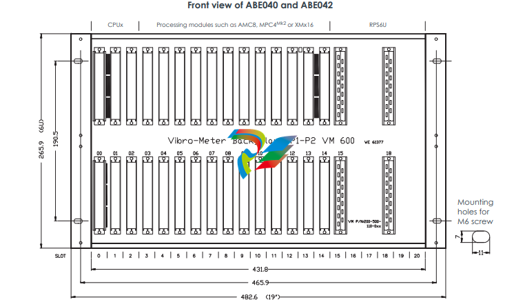
Rack slots
(module (card) positions)
: Front of rack:
• 12 × slots – module (card) positions 03 to 14 – for processing
modules (cards) such as MPC4Mk2, XMx16, MPC4 and/or AMC8.
• 2 × slots – module (card) positions 00 to 01 – for rack controller
and communications interface modules (cards) such as CPUMMk2
or CPUx.
• 1 × slot – module (card) position 02 – reserved for applicationspecific modules (cards).
Rear of rack:
• Up to 19 × slots – module (card) positions 00 to 18 – for associated
input/output modules (cards) such as IOC4Mk2, XIO16T, IOC4T and/
or IOC8T, IOCNMk2 or IOCx, and relay modules (cards) such as
RLC16Mk2, RLC16 and/or IRC4.
• Up to 4 × slots – module (card) positions 17 to 20 – for associated
rear panels for inputs to the VM600Mk2/VM600 RPS6U rack power
supply or supplies.
See also Mechanical drawings – front and rear views on page 6.
Notes
In general, associated input/output modules (cards) are required
while relay modules (cards) are optional.
For safety reasons, any VM600Mk2/VM600 rack slot not populated
by a module (card) must be covered by a blank panel(s).
Rack slot number coding : For modules (cards) installed in the rear of an ABE04x rack, an
electronic keying mechanism known as slot number coding is used
to help ensure that the module (card) is installed in the correct slot,
as defined by the configuration (that is, by the VibroSight® or
VM600 MPSx software).
For ABE04x racks, the rack’s slot numbers are fixed (hard-wired) and
slot number coding requires that a module’s slot number is set to
match the rack slot (module (card) position) where it is installed.
Slot number coding range : 3 to 14
Slot number coding defaults : Fixed (hard-wired) as follows:
• Slot 03 = 3 (0011 binary)
• Slot 04 = 4 (0100 binary)
…
• Slot 13 = 13 (1101 binary)
• Slot 14 = 14 (1110 binary).
Galvanic separation : Galvanic separation units (GSIxxx) are available for accelerometer
and proximity systems mounted in explosive atmospheres. These
units cannot be supplied by the rack and require an external power
supply. They must be mounted outside the rack in a remote housing
or in a cabinet.
Power supply
VM600Mk2/VM600 RPS6U rack power
supplies
: A VM600Mk2/VM600 ABE04x system rack can have either one or
two RPS6U rack power supplies installed, as follows:
• 1 × RPS6U power supply (330 W) supports the power requirements
for a full rack of modules (cards) in applications with operating
temperatures up to 50°C (122°F).
• 2 × RPS6U power supplies (330 W) – operating redundantly –
supports the power requirements for a full rack of modules (cards)
in applications with operating temperatures up to 50°C (122°F).
With this rack power supply redundancy, if one RPS6U fails, the
other will provide 100% of the rack’s power requirements so that the
rack will continue to operate.
Note: This is known as a redundant RPS6U rack power supply
configuration.
• 2 × RPS6U power supplies (330 W) – operating non-redundantly –
supports the power requirements for a full rack of modules (cards)
in applications with operating temperatures above 50°C (122°F),
where RPS6U output power derating is required.
Note: Even though two RPS6U rack power supplies are installed in
the rack, this is not a redundant RPS6U rack power supply
configuration.
Refer to the VM600Mk2/VM600 RPS6U rack power supplies
data sheet and a VM600Mk2/VM600 machinery protection system
(MPS) hardware manual for further information.
Power supply check relay
Nominal switching capacity
(resistive load)
: 4 A / 250 VAC, 3 A / 30 VDC
Maximum switching power
(resistive load)
: 1000 VA, 90 W
Maximum switching voltage : ±30 VRMS / ±42.4 VAC(PEAK) or 60 VDC
Maximum switching current : 4 AAC, 3 ADC
Environmental
According to IEC 60068-2 recommendations
Temperature
• Operating : 0 to 70°C (32 to 158°F)
• Storage : −40 to 85°C (−40 to 185°F)
Humidity : 0 to 90%, non-condensing
Vibration : 10 to 55 Hz, 0.35 mm peak, 6 hours in each direction
Shock : 15 g peak, 11 ms, half-sine pulse
Indoor use : Limited to indoor use only
Approvals
Conformity : European Union (EU) declaration of conformity (CE marking).
CCSAUS certificate of compliance.
EAC marking, Eurasian Customs Union (EACU) certificate/
declaration of conformity.
Electromagnetic compatibility : IEC/EN 61000-6-2 and IEC/EN 61000-6-4.
TR CU 020/2011.
Electrical safety : IEC/EN 61010-1.
TR CU 004/2011.
Vibration : IEC 60255-21-1 (Class 2)
Environmental management : RoHS compliant
Russian federal agency for technical
regulation and metrology (Rosstandart)
: Pattern approval certificate OC.C.28.004.A N° 60224
Physical
Dimensions : See Mechanical drawings starting on page 4
Weight : 6.5 kg (14.3 lb) approx.
without RPS6U power supplies and modules (cards)
S
Type Designation Ordering number (PNR)
ABE040 Different versions of the VM600Mk2 ABE040 system rack:
– Standard version 204-040-100-016
ABE040 Different versions of the VM600Mk2/VM600 ABE040 system rack:
– Standard version 204-040-100-015
– Varnished version, with a conformal coating for additional
environmental protection 204-040-100-015L
– Separate circuits version, in accordance with the IEC 60255-5 standard 204-040-100-115
– CCSAUS version, in accordance with the IEC 61010-1 standard 204-040-100-214
ABE042 Different versions of the VM600Mk2/VM600 ABE042 system rack:
– Version with mounting brackets positioned at the rear of the rack 204-042-100-01h
– Varnished version, with a conformal coating for additional
environmental protection 204-042-100-01hL
Different blank panel kits for the front of a VM600Mk2 ABE04x system rack:
– 1 × slot wide / 4 HP (TE) 200-505-011-012
– 3 × slots wide / 12 HP (TE) 200-505-018-012
Different blank panel kits for the rear of a VM600Mk2 ABE04x system rack:
– 1 × slot wide / 4 HP (TE) 200-505-011-012
Different blank panel kits for the front of a VM600 ABE04x system rack:
– 1 × slot wide / 4 HP (TE) 200-505-015-011
– 2 × slots wide / 8 HP (TE) 200-505-016-011
– 3 × slots wide / 12 HP (TE) 200-505-018-011
– 4 × slots wide / 16 HP (TE) 200-505-017-011
Different blank panel kits for the rear of a VM600 ABE04x system rack:
– 1 × slot wide / 4 HP (TE) 200-505-011-011
– 2 × slots wide / 8 HP (TE) 200-505-012-011
– 4 × slots wide / 16 HP (TE) 200-505-013-011
Notes
In an ordering number (PNR), “h” represents the hardware version.
The standard version of the VM600Mk2 ABE040 system rack (PNR 204-040-100-016) and the standard version of the VM600Mk2/VM600
ABE040 system rack (PNR 204-040-100-015 or earlier) are the same, except for the specific artwork/branding/finish. More specifically,
the mounting brackets on the side of the ABE040 system rack are bare aluminium for the VM600Mk2 versions and painted for the
VM600Mk2/VM600 versions. See also Ordering guidelines on page 9.
For safety reasons, any VM600Mk2/VM600 ABE04x system rack slot not populated by a module (card) must be covered by a blank
panel(s).
(The width of a 19″ rack is typically measured in horizontal pitch (HP) units of 5.08 mm (0.2″), also known as standard width (TE) units.
For the VM600Mk2/VM600 ABE04x System racks, a 1 × slot wide blank panel suitable for covering one module (card) position
corresponds to 4 HP (TE), a 2 × slots wide blank panel corresponds to 8 HP (TE), a 3 × slots wide blank panel corresponds to 12 HP (TE)
and so on.)
When only one RPS6U power supply is installed in a VM600Mk2/VM600 ABE04x system rack (PS1 in rack slots 18 to 20), the unused
power supply position (PS2 in rack slots 15 to 17) should be populated with a blank panel(s).
ORDERING GUIDELINES
The ordering numbers (PNRs) given in Ordering information on page 8 of this data sheet should be used when
ordering a VM600Mk2/VM600 ABE04x system rack and/or blank panels as individual system components for use
as a replacement or spare part.
However, when ordering these components with other system components as part of a complete
VM600Mk2/VM600 machinery monitoring system, then a VM600SYS-based ordering number should be used.
Contact your local Meggitt representative for further information.
RELATED PRODUCTS
VM600Mk2 (second generation)
ABE056 VM600Mk2/VM600 slimline rack : Refer to corresponding data sheet
ASPS VM600Mk2/VM600 auxiliary sensor power
supply
: Refer to corresponding data sheet
CPUMMk2 + IOCNMk2 VM600Mk2 rack controller and
communications interface module
: Refer to corresponding data sheet
MPC4Mk2 + IOC4Mk2 VM600Mk2 machinery protection and
condition monitoring module
: Refer to corresponding data sheet
RLC16Mk2 VM600Mk2 relay module : Refer to corresponding data sheet
RPS6U VM600Mk2/VM600 rack power supplies : Refer to corresponding data sheet
XMx16 + XIO16T VM600Mk2/VM600 condition monitoring
modules
: Refer to corresponding data sheet
VibroSight VibroSight® machinery monitoring system
software
: Refer to corresponding data sheet
VM600 (first generation)
ABE056 VM600Mk2/VM600 slimline rack : Refer to corresponding data sheet
AMC8 and IOC8T VM600 analog monitoring card pair : Refer to corresponding data sheet
ASPS VM600Mk2/VM600 auxiliary sensor power
supply
: Refer to corresponding data sheet
CPUM and IOCN VM600 modular CPU card and
input/output card.
Note: With a front-panel display and support
for Modbus RTU/TCP or PROFINET.
: Refer to corresponding data sheet
CPUR and IOCR VM600 rack controller and communications
interface card pair.
Note: With rack controller redundancy and
support for Modbus RTU/TCP.
: Refer to corresponding data sheet
CPUR2 and IOCR2 VM600 rack controller and communications
interface card pair.
Note: With mathematical processing of
fieldbus data and support for Modbus TCP
and PROFIBUS.
: Refer to corresponding data sheet
IRC4 VM600 intelligent relay card : Refer to corresponding data sheet
MPC4 and IOC4T VM600 machinery protection card pair : Refer to corresponding data sheets
RLC16 VM600 relay card : Refer to corresponding data sheet
RPS6U VM600Mk2/VM600 rack power supplies : Refer to corresponding data sheet
XMx16 + XIO16T VM600Mk2/VM600 condition monitoring
modules
: Refer to corresponding data sheet
Meggitt (Meggitt PLC) is a leading international engineering company, headquartered in England, that designs and delivers high-performance
components and subsystems for aerospace, defence and selected energy markets. Meggitt comprises four customer-aligned divisions:
Airframe Systems, Engine Systems, Energy & Equipment and Services & Support.
The Energy & Equipment division includes the Energy Sensing and Controls product group that specialises in sensing and monitoring solutions for a
broad range of energy infrastructure, and control valves for industrial gas turbines, primarily for the Power Generation, Oil & Gas and Services markets.
Energy & Equipment is headquartered in Switzerland (Meggitt SA) and incorporates the vibro-meter® product line, which has over 65 years of sensor
and systems expertise and is trusted by original equipment manufacturers (OEMs) globally.
All information in this document, such as descriptions, specifications, drawings, recommendations and other statements, is believed to be
reliable and is stated in good faith as being approximately correct, but is not binding on Meggitt (Meggitt SA) unless expressly agreed in
writing. Before acquiring and/or using this product, you must evaluate it and determine if it is suitable for your intended application. You
should also check our website at www.meggittsensing.com/energy for any updates to data sheets, certificates, product drawings, user
manuals, service bulletins and/or other instructions affecting the product.
Unless otherwise expressly agreed in writing with Meggitt SA, you assume all risks and liability associated with use of the product. Any
recommendations and advice given without charge, whilst given in good faith, are not binding on Meggitt SA. Meggitt (Meggitt SA) takes
no responsibility for any statements related to the product which are not contained in a current Meggitt SA publication, nor for any
statements contained in extracts, summaries, translations or any other documents not authored and produced by Meggitt SA.
The certifications and warranties applicable to the products supplied by Meggitt SA are valid only for new products purchased directly from
Meggitt SA or from an authorised distributor of Meggitt SA.
In this publication, a dot (.) is used as the decimal separator and thousands are separated by thin spaces. Example: 12345.67890.
Copyright© 2022 Meggitt SA. All rights reserved. The information contained in this document is subject to change without prior noticeKEY FEATURES AND BENEFITS
• From the vibro-meter® product line
• 19″ system racks with a standard height of 6U
• Robust aluminium construction
• Modular concept allows specific cards to be
added for machinery protection and/or
condition monitoring
• Cabinet or panel mounting
• Backplane supporting the VME bus, the
VM600Mk2/VM600 system’s Tacho, Raw and
Open collector (OC) buses, and power supply
distribution
• Uses the VM600Mk2/VM600 RPS6U rack power
supply: AC and/or DC input versions
• Power supply check relay
APPLICATIONS
• VM600Mk2/VM600 machinery protection and/
or condition monitoring systems
DESCRIPTION
The VM600Mk2/VM600 ABE040 and ABE042 system
racks are used to house hardware for the
VM600Mk2/VM600 series of machinery protection
and/or condition monitoring systems, from
Meggitt’s vibro-meter® product line.
Two types of VM600Mk2/VM600 ABE04x system
rack are available: the ABE040 and the ABE042.
These are very similar, differing only in the position
of the mounting brackets. Both racks have a
standard height of 6U and provide mounting
space (rack slots) for up to 12 single-width
VM600Mk2/VM600 modules (card pairs), or a
combination of single-width and multiple-width
modules (cards). These racks are particularly
suitable for industrial environments, where
equipment must be permanently installed in 19″
cabinets or panels.
DESCRIPTION (continued)
The different versions of ABE04x system rack
enable different mounting options to support
various markets and applications.
The VM600 system rack has an integrated VME
backplane which provides the electrical
interconnections between the installed
VM600Mk2/VM600 modules (cards): power supply,
signal processing, input /output, relay and
CPUx “rack controller”. It also includes a power
supply check relay, available at the rear of the
rack, which is used to indicate that the installed
RPS6U rack power supplies are operating
normally.
Either one or two RPS6U rack power supplies can
be installed in a VM600Mk2/VM600 ABE04x system
rack. A rack with one RPS6U power supply (330 W
version) supports the power requirements for a full
rack of modules (cards) in applications with
operating temperatures up to 50°C (122°F).
Alternatively, a rack can have two RPS6U power
supplies installed in order to either support rack
power supply redundancy or in order to supply
power to the modules (cards) non-redundantly
over a wider range of environmental conditions
(see Power supply on page 4).
VM600Mk2/VM600 processing modules (cards) are
installed in the front of the rack and the
associated input/output modules (cards) are
installed in the rear. The input/output modules
(cards) provide connectors for the connection of
sensors/measurement chains and for the sharing
of various signals with external systems such as a
DCS or PLC.
In general, VM600Mk2/VM600 ABE04x system racks
are configured in the factory before delivery so
they are supplied ready-to-use. Optionally, each
module (card) can be reconfigured to meet the
needs of a particular machinery monitoring
application using the appropriate software
package from Meggitt vibro-meter®:
VM600 MPSx or VibroSight®.
For further information, contact your local
Meggitt representative.
General
Housing : Extruded aluminium frame and solid aluminium structural parts.
Top and bottom plastic guide strips for VM600Mk2/VM600 modules
(cards).
Colour : Aluminium
Power supply : The VM600Mk2/VM600 RPS6U rack power supply is used to provide
the VM600Mk2/VM600 rack itself and all installed modules (cards)
with +5 VDC and ±12 VDC.
See also Power supply on page 4.
Power supply inputs : Power supply inputs (associated rear panels) typically have an AC
and/or DC connector (with RFI filters), on/off switches and fuses.
Refer to the VM600Mk2/VM600 RPS6U rack power supplies
data sheet for information on power supply inputs, associated rear
panels and mains power supply leads (power cords).
Backplane : Proprietary VM600Mk2/VM600 rack buses (Tacho bus, Raw bus and
Open collector (OC) bus) for data/signal sharing between modules
(cards).
VME bus for communication between CPUx modules (cards) and
processing modules (cards).
General
Housing : Extruded aluminium frame and solid aluminium structural parts.
Top and bottom plastic guide strips for VM600Mk2/VM600 modules
(cards).
Colour : Aluminium
Power supply : The VM600Mk2/VM600 RPS6U rack power supply is used to provide
the VM600Mk2/VM600 rack itself and all installed modules (cards)
with +5 VDC and ±12 VDC.
See also Power supply on page 4.
Power supply inputs : Power supply inputs (associated rear panels) typically have an AC
and/or DC connector (with RFI filters), on/off switches and fuses.
Refer to the VM600Mk2/VM600 RPS6U rack power supplies
data sheet for information on power supply inputs, associated rear
panels and mains power supply leads (power cords).
Backplane : Proprietary VM600Mk2/VM600 rack buses (Tacho bus, Raw bus and
Open collector (OC) bus) for data/signal sharing between modules
(cards).
VME bus for communication between CPUx modules (cards) and
processing modules (cards).
Rack slots
(module (card) positions)
: Front of rack:
• 12 × slots – module (card) positions 03 to 14 – for processing
modules (cards) such as MPC4Mk2, XMx16, MPC4 and/or AMC8.
• 2 × slots – module (card) positions 00 to 01 – for rack controller
and communications interface modules (cards) such as CPUMMk2
or CPUx.
• 1 × slot – module (card) position 02 – reserved for applicationspecific modules (cards).
Rear of rack:
• Up to 19 × slots – module (card) positions 00 to 18 – for associated
input/output modules (cards) such as IOC4Mk2, XIO16T, IOC4T and/
or IOC8T, IOCNMk2 or IOCx, and relay modules (cards) such as
RLC16Mk2, RLC16 and/or IRC4.
• Up to 4 × slots – module (card) positions 17 to 20 – for associated
rear panels for inputs to the VM600Mk2/VM600 RPS6U rack power
supply or supplies.
See also Mechanical drawings – front and rear views on page 6.
Notes
In general, associated input/output modules (cards) are required
while relay modules (cards) are optional.
For safety reasons, any VM600Mk2/VM600 rack slot not populated
by a module (card) must be covered by a blank panel(s).
Rack slot number coding : For modules (cards) installed in the rear of an ABE04x rack, an
electronic keying mechanism known as slot number coding is used
to help ensure that the module (card) is installed in the correct slot,
as defined by the configuration (that is, by the VibroSight® or
VM600 MPSx software).
For ABE04x racks, the rack’s slot numbers are fixed (hard-wired) and
slot number coding requires that a module’s slot number is set to
match the rack slot (module (card) position) where it is installed.
Slot number coding range : 3 to 14
Slot number coding defaults : Fixed (hard-wired) as follows:
• Slot 03 = 3 (0011 binary)
• Slot 04 = 4 (0100 binary)
…
• Slot 13 = 13 (1101 binary)
• Slot 14 = 14 (1110 binary).
Galvanic separation : Galvanic separation units (GSIxxx) are available for accelerometer
and proximity systems mounted in explosive atmospheres. These
units cannot be supplied by the rack and require an external power
supply. They must be mounted outside the rack in a remote housing
or in a cabinet.
Power supply
VM600Mk2/VM600 RPS6U rack power
supplies
: A VM600Mk2/VM600 ABE04x system rack can have either one or
two RPS6U rack power supplies installed, as follows:
• 1 × RPS6U power supply (330 W) supports the power requirements
for a full rack of modules (cards) in applications with operating
temperatures up to 50°C (122°F).
• 2 × RPS6U power supplies (330 W) – operating redundantly –
supports the power requirements for a full rack of modules (cards)
in applications with operating temperatures up to 50°C (122°F).
With this rack power supply redundancy, if one RPS6U fails, the
other will provide 100% of the rack’s power requirements so that the
rack will continue to operate.
Note: This is known as a redundant RPS6U rack power supply
configuration.
• 2 × RPS6U power supplies (330 W) – operating non-redundantly –
supports the power requirements for a full rack of modules (cards)
in applications with operating temperatures above 50°C (122°F),
where RPS6U output power derating is required.
Note: Even though two RPS6U rack power supplies are installed in
the rack, this is not a redundant RPS6U rack power supply
configuration.
Refer to the VM600Mk2/VM600 RPS6U rack power supplies
data sheet and a VM600Mk2/VM600 machinery protection system
(MPS) hardware manual for further information.
Power supply check relay
Nominal switching capacity
(resistive load)
: 4 A / 250 VAC, 3 A / 30 VDC
Maximum switching power
(resistive load)
: 1000 VA, 90 W
Maximum switching voltage : ±30 VRMS / ±42.4 VAC(PEAK) or 60 VDC
Maximum switching current : 4 AAC, 3 ADC
Environmental
According to IEC 60068-2 recommendations
Temperature
• Operating : 0 to 70°C (32 to 158°F)
• Storage : −40 to 85°C (−40 to 185°F)
Humidity : 0 to 90%, non-condensing
Vibration : 10 to 55 Hz, 0.35 mm peak, 6 hours in each direction
Shock : 15 g peak, 11 ms, half-sine pulse
Indoor use : Limited to indoor use only
Approvals
Conformity : European Union (EU) declaration of conformity (CE marking).
CCSAUS certificate of compliance.
EAC marking, Eurasian Customs Union (EACU) certificate/
declaration of conformity.
Electromagnetic compatibility : IEC/EN 61000-6-2 and IEC/EN 61000-6-4.
TR CU 020/2011.
Electrical safety : IEC/EN 61010-1.
TR CU 004/2011.
Vibration : IEC 60255-21-1 (Class 2)
Environmental management : RoHS compliant
Russian federal agency for technical
regulation and metrology (Rosstandart)
: Pattern approval certificate OC.C.28.004.A N° 60224
Physical
Dimensions : See Mechanical drawings starting on page 4
Weight : 6.5 kg (14.3 lb) approx.
without RPS6U power supplies and modules (cards)
S
Type Designation Ordering number (PNR)
ABE040 Different versions of the VM600Mk2 ABE040 system rack:
– Standard version 204-040-100-016
ABE040 Different versions of the VM600Mk2/VM600 ABE040 system rack:
– Standard version 204-040-100-015
– Varnished version, with a conformal coating for additional
environmental protection 204-040-100-015L
– Separate circuits version, in accordance with the IEC 60255-5 standard 204-040-100-115
– CCSAUS version, in accordance with the IEC 61010-1 standard 204-040-100-214
ABE042 Different versions of the VM600Mk2/VM600 ABE042 system rack:
– Version with mounting brackets positioned at the rear of the rack 204-042-100-01h
– Varnished version, with a conformal coating for additional
environmental protection 204-042-100-01hL
Different blank panel kits for the front of a VM600Mk2 ABE04x system rack:
– 1 × slot wide / 4 HP (TE) 200-505-011-012
– 3 × slots wide / 12 HP (TE) 200-505-018-012
Different blank panel kits for the rear of a VM600Mk2 ABE04x system rack:
– 1 × slot wide / 4 HP (TE) 200-505-011-012
Different blank panel kits for the front of a VM600 ABE04x system rack:
– 1 × slot wide / 4 HP (TE) 200-505-015-011
– 2 × slots wide / 8 HP (TE) 200-505-016-011
– 3 × slots wide / 12 HP (TE) 200-505-018-011
– 4 × slots wide / 16 HP (TE) 200-505-017-011
Different blank panel kits for the rear of a VM600 ABE04x system rack:
– 1 × slot wide / 4 HP (TE) 200-505-011-011
– 2 × slots wide / 8 HP (TE) 200-505-012-011
– 4 × slots wide / 16 HP (TE) 200-505-013-011
Notes
In an ordering number (PNR), “h” represents the hardware version.
The standard version of the VM600Mk2 ABE040 system rack (PNR 204-040-100-016) and the standard version of the VM600Mk2/VM600
ABE040 system rack (PNR 204-040-100-015 or earlier) are the same, except for the specific artwork/branding/finish. More specifically,
the mounting brackets on the side of the ABE040 system rack are bare aluminium for the VM600Mk2 versions and painted for the
VM600Mk2/VM600 versions. See also Ordering guidelines on page 9.
For safety reasons, any VM600Mk2/VM600 ABE04x system rack slot not populated by a module (card) must be covered by a blank
panel(s).
(The width of a 19″ rack is typically measured in horizontal pitch (HP) units of 5.08 mm (0.2″), also known as standard width (TE) units.
For the VM600Mk2/VM600 ABE04x System racks, a 1 × slot wide blank panel suitable for covering one module (card) position
corresponds to 4 HP (TE), a 2 × slots wide blank panel corresponds to 8 HP (TE), a 3 × slots wide blank panel corresponds to 12 HP (TE)
and so on.)
When only one RPS6U power supply is installed in a VM600Mk2/VM600 ABE04x system rack (PS1 in rack slots 18 to 20), the unused
power supply position (PS2 in rack slots 15 to 17) should be populated with a blank panel(s).
ORDERING GUIDELINES
The ordering numbers (PNRs) given in Ordering information on page 8 of this data sheet should be used when
ordering a VM600Mk2/VM600 ABE04x system rack and/or blank panels as individual system components for use
as a replacement or spare part.
However, when ordering these components with other system components as part of a complete
VM600Mk2/VM600 machinery monitoring system, then a VM600SYS-based ordering number should be used.
Contact your local Meggitt representative for further information.
RELATED PRODUCTS
VM600Mk2 (second generation)
ABE056 VM600Mk2/VM600 slimline rack : Refer to corresponding data sheet
ASPS VM600Mk2/VM600 auxiliary sensor power
supply
: Refer to corresponding data sheet
CPUMMk2 + IOCNMk2 VM600Mk2 rack controller and
communications interface module
: Refer to corresponding data sheet
MPC4Mk2 + IOC4Mk2 VM600Mk2 machinery protection and
condition monitoring module
: Refer to corresponding data sheet
RLC16Mk2 VM600Mk2 relay module : Refer to corresponding data sheet
RPS6U VM600Mk2/VM600 rack power supplies : Refer to corresponding data sheet
XMx16 + XIO16T VM600Mk2/VM600 condition monitoring
modules
: Refer to corresponding data sheet
VibroSight VibroSight® machinery monitoring system
software
: Refer to corresponding data sheet
VM600 (first generation)
ABE056 VM600Mk2/VM600 slimline rack : Refer to corresponding data sheet
AMC8 and IOC8T VM600 analog monitoring card pair : Refer to corresponding data sheet
ASPS VM600Mk2/VM600 auxiliary sensor power
supply
: Refer to corresponding data sheet
CPUM and IOCN VM600 modular CPU card and
input/output card.
Note: With a front-panel display and support
for Modbus RTU/TCP or PROFINET.
: Refer to corresponding data sheet
CPUR and IOCR VM600 rack controller and communications
interface card pair.
Note: With rack controller redundancy and
support for Modbus RTU/TCP.
: Refer to corresponding data sheet
CPUR2 and IOCR2 VM600 rack controller and communications
interface card pair.
Note: With mathematical processing of
fieldbus data and support for Modbus TCP
and PROFIBUS.
: Refer to corresponding data sheet
IRC4 VM600 intelligent relay card : Refer to corresponding data sheet
MPC4 and IOC4T VM600 machinery protection card pair : Refer to corresponding data sheets
RLC16 VM600 relay card : Refer to corresponding data sheet
RPS6U VM600Mk2/VM600 rack power supplies : Refer to corresponding data sheet
XMx16 + XIO16T VM600Mk2/VM600 condition monitoring
modules
: Refer to corresponding data sheet
Meggitt (Meggitt PLC) is a leading international engineering company, headquartered in England, that designs and delivers high-performance
components and subsystems for aerospace, defence and selected energy markets. Meggitt comprises four customer-aligned divisions:
Airframe Systems, Engine Systems, Energy & Equipment and Services & Support.
The Energy & Equipment division includes the Energy Sensing and Controls product group that specialises in sensing and monitoring solutions for a
broad range of energy infrastructure, and control valves for industrial gas turbines, primarily for the Power Generation, Oil & Gas and Services markets.
Energy & Equipment is headquartered in Switzerland (Meggitt SA) and incorporates the vibro-meter® product line, which has over 65 years of sensor
and systems expertise and is trusted by original equipment manufacturers (OEMs) globally.
All information in this document, such as descriptions, specifications, drawings, recommendations and other statements, is believed to be
reliable and is stated in good faith as being approximately correct, but is not binding on Meggitt (Meggitt SA) unless expressly agreed in
writing. Before acquiring and/or using this product, you must evaluate it and determine if it is suitable for your intended application. You
should also check our website at www.meggittsensing.com/energy for any updates to data sheets, certificates, product drawings, user
manuals, service bulletins and/or other instructions affecting the product.
Unless otherwise expressly agreed in writing with Meggitt SA, you assume all risks and liability associated with use of the product. Any
recommendations and advice given without charge, whilst given in good faith, are not binding on Meggitt SA. Meggitt (Meggitt SA) takes
no responsibility for any statements related to the product which are not contained in a current Meggitt SA publication, nor for any
statements contained in extracts, summaries, translations or any other documents not authored and produced by Meggitt SA.
The certifications and warranties applicable to the products supplied by Meggitt SA are valid only for new products purchased directly from
Meggitt SA or from an authorised distributor of Meggitt SA.
In this publication, a dot (.) is used as the decimal separator and thousands are separated by thin spaces. Example: 12345.67890.
Copyright© 2022 Meggitt SA. All rights reserved. The information contained in this document is subject to change without prior notice
Leave a comment
Your email address will not be published. Required fields are marked *