Features
• 1-channel signal conditioner
• 24 V DC supply (Power Rail)
• Input for 2- or 3-wire sensors, NAMUR sensors or dry
contacts
• Input frequency 1 mHz … 10 kHz
• Current output 0/4 mA … 20 mA
• Relay contact and transistor output
• Start-up override
• Line fault detection (LFD)
• Up to SIL 2 acc. to IEC 61508/IEC 61511
Function
This signal conditioner provides the isolation for nonintrinsically safe applications.
The device is a universal frequency converter that changes a
digital input signal into a proportional free adjustable
0/4 mA … 20 mA analog output signal and functions as a
switch amplifier and a trip alarm.
The functions of the switch outputs (2 relay outputs and
1 potential free transistor output) are easily adjustable [trip
value display (min/max alarm), serially switched output, pulse
divider output, error signal output].
The device is easily configured by the use of keypad or with
the PACTware configuration software.
A fault is signalized by LEDs acc. to NAMUR NE44 and a
separate collective error message output.
For additional information, refer to the manual and
www.pepperl-fuchs.com.
General specifications
Signal type Digital Input
Functional safety related parameters
Safety Integrity Level (SIL) SIL 2
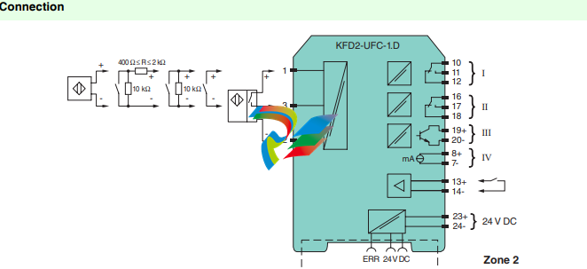
Supply
Connection terminals 23+, 24- or power feed module/Power Rail
Rated voltage Ur 20 … 30 V DC
Rated current Ir approx. 100 mA
Power dissipation/power consumption ≤ 2 W / 2.2 W
Interface
Programming interface programming socket
Input
Connection side field side
Connection Input I: 2-wire sensor: terminals 1+, 3- three wire sensor: terminals 1+, 2- and 3
input II: terminals 13+, 14- start-up override;
Input I 2- or 3-wire sensor, sensor acc. to EN 60947-5-6 (NAMUR) or mechanical contact
Open circuit voltage/short-circuit
current
22 V / 40 mA
Input resistance 4.7 kΩ
Switching point/switching hysteresis logic 1: > 2.5 mA ; logic 0: < 1.9 mA
Pulse duration > 50 µs
Input frequency 0.001 … 10000 Hz
Line fault detection breakage I ≤ 0.15 mA; short-circuit I > 4 mA
Input II startup override: 1 … 1000 s, adjustable in steps of 1 s
Active/Passive I > 4 mA (for min. 100 ms) / I < 1.5 mA
Open circuit voltage/short-circuit
current
18 V / 5 mA
Output
Connection side control side
Connection output I: terminals 10, 11, 12
output II: terminals 16, 17, 18
outout III: terminasl 19+, 20-
output IV: terminals 8+, 7-
Output I, II signal, relay
Contact loading 250 V AC / 2 A / cos φ ≥ 0.7 ; 40 V DC / 2 A
Mechanical life 5 x 10⁷ switching cycles
Energized/De-energized delay approx. 20 ms / approx. 20 ms
Output III electronic output, passive
Contact loading 40 V DC
Signal level 1-signal: (L+) -2.5 V (50 mA, short-circuit/overload proof)
0-signal: blocked output (off-state current ≤ 10 µA)
Output IV analog
Current range 0 … 20 mA or 4 … 20 mA
Open loop voltage ≤ 24 V DC
Load ≤ 650 Ω
Fault signal downscale I ≤ 3.6 mA , upscale ≥ 21.5 mA (acc. NAMUR NE43)
Collective error message Power Rail
Transfer characteristics
Input I
Measurement range 0.001 … 10000 Hz
Resolution 0.1 % of the measurement value , ≥ 0.001 Hz
Accuracy 0.1 % of the measurement value , > 0.001 Hz
Measuring time < 100 ms
Influence of ambient temperature 0.003 %/K (30 ppm)
Output I, II
Response delay ≤ 200 ms
Output IV
Resolution < 10 µA
Accuracy < 20 µA
Influence of ambient temperature 0.005 %/K (50 ppm)
Galvanic isolation
Input I/other circuits reinforced insulation according to IEC/EN 61010-1, rated insulation voltage 300 Veff
Output I, II/other circuits reinforced insulation according to IEC/EN 61010-1, rated insulation voltage 300 Veff
Mutual output I, II, III reinforced insulation according to IEC/EN 61010-1, rated insulation voltage 300 Veff
Output III/power supply and collective
error
basic insulation according to IEC/EN 61010-1, rated insulation voltage 50 Veff
Output III/IV basic insulation according to IEC/EN 61010-1, rated insulation voltage 50 Veff
Output IV/power supply and collective
error
functional insulation acc. to IEC 62103, rated insulation voltage 50 Veff
Start-up override/power supply and
collective error
functional insulation acc. to IEC 62103, rated insulation voltage 50 Veff
Interface/power supply and collective
error
functional insulation acc. to IEC 62103, rated insulation voltage 50 Veff
Interface/output III basic insulation according to IEC/EN 61010-1, rated insulation voltage 50 Veff
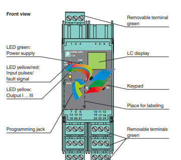
Indicators/settings
Display elements LEDs , display
Control elements Control panel
Configuration via operating buttons
via PACTware
Labeling space for labeling at the front
Directive conformity
Electromagnetic compatibility
Directive 2014/30/EU EN 61326-1:2013 (industrial locations)
Low voltage
Directive 2014/35/EU EN 61010-1:2010
Conformity
Electromagnetic compatibility NE 21:2006
Degree of protection IEC 60529:2001
Ambient conditions
Ambient temperature -20 … 60 °C (-4 … 140 °F)
Mechanical specifications
Degree of protection IP20
Connection screw terminals
Mass 300 g
Dimensions 40 x 119 x 115 mm (1.6 x 4.7 x 4.5 inch) , housing type C3
Mounting on 35 mm DIN mounting rail acc. to EN 60715:2001
Data for application in connection
with hazardous areas
Certificate PF 08 CERT 1216 X
Marking ¬ II 3G Ex nA nC IIC T4 Gc
Output I, II
Contact loading 50 V AC/2 A/cos φ > 0.7; 40 V DC/1 A resistive load
Ambient conditions
Ambient temperature -20 … 50 °C (-4 … 122 °F)
Directive conformity
Directive 2014/34/EU EN 60079-0:2012+A11:2013 , EN 60079-15:2010
International approvals
UL approval E223772
Leave a comment
Your email address will not be published. Required fields are marked *