This manual describes how to install, setup, and operate a
CAS200. Included are six chapters and a glossary of terms.
Each chapter covers a different aspect of the alarm scanner
and may apply to different users. The following describes
the chapters and their purpose.
• Chapter 1: System Overview provides a component
list and summary of features for the CAS200 series
alarm scanners.
• Chapter 2: Installation provides detailed
instructions on installing the CAS200 and its
peripherals.
• Chapter 3: Using the CAS200 provides an overview
of operator displays used for system monitoring and
job selection.
• Chapter 4: Setup provides detailed descriptions of all
menus and parameters for scanner setup.
• Chapter 5: Troubleshooting and
Reconfiguration provides some basic guidelines for
solving operational problems and provides procedures
for changing some of the hardware options (e.g.
installing special input resistors and changing EIA/
TIA-232 to EIA/TIA-485).
• Chapter 6: Linear Scaling Examples provides
three examples where linear scaling is used.
• Chapter 7: Specifications lists detailed
specifications of the scanner and optional components.
Product Features
The CAS200 is a modular monitoring system with 16
analog inputs. It can function as a stand-alone system; the
CAS200 1/8 DIN front panel has a Vacuum Fluorescent
Display (VFD) and touch keypad for local display and local
parameter entry. You can also use it as the key element in
a computer supervised data acquisition system; the
CAS200 can be locally or remotely controlled via an EIA/
TIA-232 or EIA/TIA-485 serial communications interface.
Features include:
Direct Connection of Mixed Thermocouple Sensors:
Connect most thermocouples to the scanner with no
hardware modifications. Thermocouple inputs feature
reference junction compensation, linearization, process
variable offset calibration to correct for sensor
inaccuracies, detection of broken, shorted or reversed
thermocouples, and a choice of Fahrenheit or Celsius
display.
Automatic Scaling for Linear Analog Inputs: The
CAS200 series automatically scales linear inputs used with
industrial process sensors. Enter two points and all input
values are automatically scaled in your units. Scaling
resistors must be installed.
Flexible Alarm Outputs: Independently set high/low
process alarms and a high/low deviation band alarm for
each channel. Alarms can activate a digital output by
themselves, or they can be grouped with other alarms to
activate an output.
Alarm Outputs: You can set high/low deviation and high/
low process alarm setpoints to operate digital outputs as
latched or unlatched functions.
Global Alarm Output: When any alarm is triggered, the
global alarm output is also triggered, and it stays on until
you acknowledge it.
CPU Watchdog: The CAS200 series CPU watchdog timer
output notifies you of system failure. Use it to hold a relay
closed while the system is running, so you are notified if the
microprocessor shuts down.
Front Panel or Computer Operation: Set up and run
the scanner from the front panel or from a local or remote
computer. Watlow Anafaze offers WatView, a Windows®
compatible Human Machine Interface (HMI) software
package that includes data logging and graphing features
in addition to process monitoring and parameter setup
screens.
Multiple Job Storage: Store up to eight jobs in protected
memory, and access them locally by entering a single job
number or remotely via digital inputs. Each job is a set of
alarm conditions.
Pulse Counter Input: Use the pulse counter input for
precise monitoring of motor or belt speed.
System Diagram
The illustration below shows how the parts of the CAS200
are connected. When unpacking your system, use the
diagram and parts list below to ensure all parts have been
shipped. Please don’t hesitate to call Watlow Anafaze if you
have problems with your shipment, or if any CAS200
components are missing or damaged.
Figure 1.1 System Components
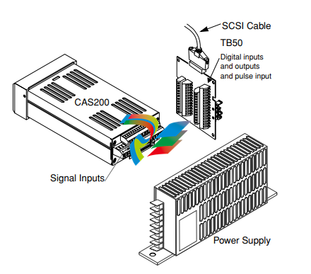
• CAS200 Scanner
• Mounting Kit
• TB50 Terminal Board
• 50-Pin SCSI Cable
• DC Power Supply
Mounting Scanner Components
Install the scanner in a location free from excessive heat
(>50°C), dust, and unauthorized handling.
Electromagnetic and radio frequency interference can
induce noise on sensor wiring. Select locations for the CAS
200 and TB50 such that wiring can be routed clear of
sources of interference such as high voltage wires, power
switching devices and motors.
∫
WARNING! To reduce the risk of fire or electric shock, install
CAS200 in a controlled environment, relatively
free of contaminants.
Safety
Watlow Anafaze has made efforts to ensure the reliability
and safety of the CAS200 and to recommend safe uses in
systems applications. Note that in any application failures
can occur.
Good engineering practices, electrical codes, and insurance
regulations require that you use independent external
safety devices to prevent potentially dangerous or unsafe
conditions. Assume that the CAS200 can fail or that other
unexpected conditions can occur.
Install high or low temperature protection in systems
where an overtemperature or undertemperature fault
condition could present a fire hazard or other hazard.
Failure to install temperature control protection where a
potential hazard exists could result in damage to
equipment and property, and injury to personnel.
For additional process safety, program a computer or other
host device to automatically reload your desired operating
parameters after a power failure. However, this safety
feature does not eliminate the need for other external,
independent safety devices in dangerous conditions.
The CAS200 should never be used as a safety
shutdown device. It should only be used with
other approved independent safety shutdown
devices.
Contact Watlow Anafaze immediately if you have any
questions about system safety or system operation.
This chapter describes how to install the CAS200 series
scanner and its peripherals. Installation of the scanner
involves the following procedures:
• Determining the best location for the scanner
• Mounting the scanner and TB50
• Power Connection
• Input Wiring
• Communications Wiring (EIA/TIA-232 or EIA/TIA485)
• Output Wiring
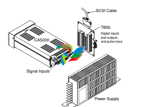
Typical Installation
The illustrations below show typical installations of the
scanner with the TB50 terminal block. Observe the
illustration below to determine potential space
requirements.
We recommend that you read this entire chapter first
before beginning the installation procedure. This will help
you to carefully plan and assess the installation.
Figure 2.1 System Components
Safety
∫
WARNING! Ensure that power has been shut off to your entire
process before you begin installation of the
scanner
Watlow Anafaze has made every effort to ensure the
reliability and safety of this product. In addition, we have
provided recommendations that will allow you to safely
install and maintain this scanner.
∫
WARNING! In any application, failures can occur. These
failures can result in full control output (100%
power), or the occurrence of other output failures
which can cause damage to the scanner, or to the
equipment or process connected to the scanner.
Therefore, always follow good engineering
practices, electrical codes, and insurance
regulations when installing and operating this
equipment.
External Safety Devices
External safety devices should be used to prevent
potentially dangerous and unsafe conditions upon
equipment failure. Always assume that this device can fail
with outputs full-On, or full-Off, by the occurrence of an
unexpected external condition.
∫
WARNING! Always install high or low temperature protection
in installations where an overtemperature or
undertemperature fault will present a potential
hazard. Failure to install external protection
devices where hazards exist can result in damage
to equipment, property, or human life.
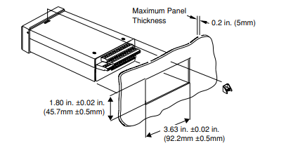
Mounting
We recommend you mount the scanner in a panel not more
than 0.2 inches thick.
∫
WARNING! To reduce the risk of fire or electric shock, install
the CAS200 in a controlled environment,
relatively free of contaminants.
Location
Install the scanner in a location free from excessive (>50°C)
heat, dust, and unauthorized handling.
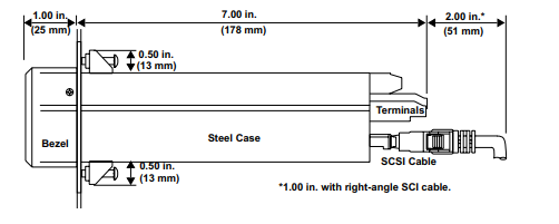
Ensure there is enough clearance for mounting brackets,
terminal blocks, and cable and wire connections; the
scanner extends 7.0 in. behind the panel face and the screw
brackets extend 0.5 in. above and below it. Allow an
additional 1 to 3 inches for the SCSI cable.
Figure 2.2 Clearance Recommendations
Other Tools:
You will also need these tools:
• Phillips head screwdriver
• Flathead screwdriver for wiring
• Multimeter
Mounting the Scanner
Mount the scanner before you mount the TB50 or do any
wiring. The scanner’s placement affects placement and
wiring considerations for the other components of your
system.
You receive one of two types of mounting brackets with
your scanner, the mini-bracket or the collar bracket. Refer
to the corresponding sections below for instructions.
Steps Using the Mini-Bracket
1. Cut a hole in the panel to the dimensions shown in the
illustration below. To do this, use a punch, nibbler, or
jigsaw, and file the edges of the hole.
2. Insert the scanner into the hole through the front of
the panel.
3. Screw the top and bottom clips in place: insert the
clip’s lip into the cutout in the scanner’s metal housing
just behind the front panel. Tighten the screws.
4. If you expect much panel vibration, use a rear support
for the scanner and its interconnecting cables.
Figure 2.3 Mounting with the Mini-Bracket
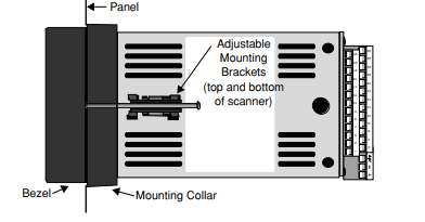
Steps Using the Collar Bracket
Installing and mounting requires access to the back of the
panel.
NOTE! Removing the scanner chassis from its case
makes mounting easier.
1. Make a panel cutout. Refer to Figure 2.3 on page 11 for
dimensions of the cutout.
2. Slide the scanner into the panel cutout.
3. Slide the mounting collar over the back of the scanner,
making sure the mounting screw indentations face
toward the back of the scanner.
4. Loosen the mounting bracket screws enough to allow
for the mounting collar and panel thickness. Place
each mounting bracket into the mounting slots (head
of the screw facing the back of the scanner). Push each
bracket backward then to the side to secure it to the
scanner case.
5. Make sure the case is seated properly. Tighten the
installation screws firmly against the mounting collar
to secure the unit. Ensure that the end of the mounting screws fit into the indentations on the mounting
collar.
Figure 2.4 Mounting with the Collar Bracket
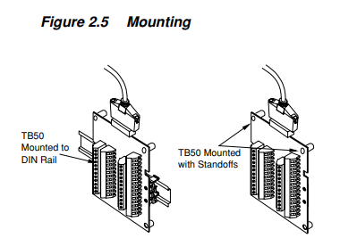
Mounting the TB50
There are two ways you can mount the TB50, by using the
pre-installed DIN rail mounting brackets provided or by
using the plastic standoffs. Follow the procedures for each
to mount the board.
Leave a comment
Your email address will not be published. Required fields are marked *