The Schneider Electric brand and any trademarks of Schneider Electric SE and its
subsidiaries referred to in this guide are the property of Schneider Electric SE or its
subsidiaries. All other brands may be trademarks of their respective owners.
This guide and its content are protected under applicable copyright laws and furnished
for informational use only. No part of this guide may be reproduced or transmitted in
any form or by any means (electronic, mechanical, photocopying, recording, or
otherwise), for any purpose, without the prior written permission of Schneider Electric.
Schneider Electric does not grant any right or license for commercial use of the guide
or its content, except for a non-exclusive and personal license to consult it on an “as is”
basis. Schneider Electric products and equipment should be installed, operated,
serviced, and maintained only by qualified personnel.
As standards, specifications, and designs change from time to time, information
contained in this guide may be subject to change without notice.
To the extent permitted by applicable law, no responsibility or liability is assumed by
Schneider Electric and its subsidiaries for any errors or omissions in the informational
content of this material or consequences arising out of or resulting from the use of the
information contained herein.
Features
Key features of the FBM232 are:
• 10 Mbps or 100 Mbps Ethernet network transmission rate to/from field device
• Communicates with up to 64 field devices
• I/O software driver is downloadable from a library of available protocols
• Up to 2000 DCI block connections
• Integrates field device data into a Foxboro DCS control database using Ethernet
connectivity
• Field mounted
• Class G3 (harsh) environments.
I/O Drivers
This fieldbus module (FBM) is a generic Ethernet hardware module in which different
software drivers can be loaded. These drivers configure the FBM to recognize a
particular protocol used by the device. Several of the software drivers are standard
product offerings. Other custom drivers can be developed to meet specific needs.
These drivers are dynamically downloaded to the FBM232 with software code
specifically designed to interface with the third party device’s protocol. The
configuration procedures and the software requirements for each driver are unique to
the device(s) being integrated into the system.
Figure 1. FBM232 in Typical Network Configuratio
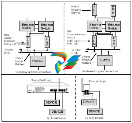
Ethernet Link Setup
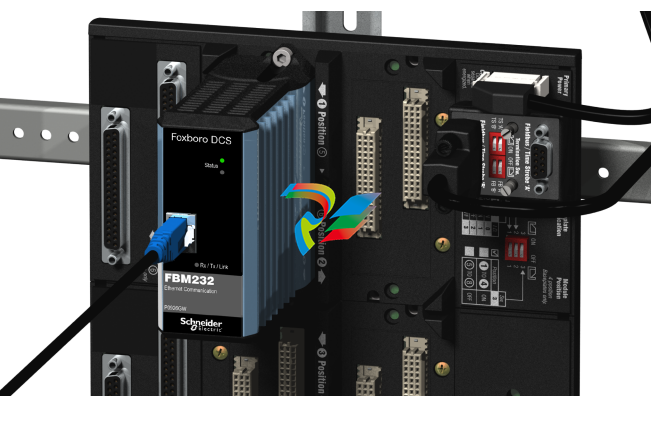
Data communication between the FBM232 and field devices are through the RJ-45
connector located on the front of the FBM232 module. The RJ-45 connector of the
FBM232 can be connected through hubs, or through Ethernet switches to the field
devices (refer to Ethernet Switches for Use with FBM232, page 12). Connection of
multiple devices to the FBM232 requires a hub or switch.
Configurator
The FDSI configurator sets up the FBM232 XML based port and device configuration
files. The port configurator allows for easy setup of the communication parameters for
each port (such as, Dynamic Host Configuration Protocol (DHCP), IP addresses). The
device configurator is not needed for all devices, but when needed it configures
device specific and point specific considerations (such as, scan rate, address of the
data to be transferred, and the amount of data to be transferred in one transaction).
Operations
The FBM232 can access up to 64 devices to read or write data. From the Foxboro
DCS control station to which the FBM232 is connected, up to 2000 Distributed Control
Interface (DCI) data connections can be made to read or write data. Supported data
types are determined by the particular driver loaded on the FBM232, which converts
the data to the DCI data types listed below:
• An analog input or output value (integer or IEEE single-precision floating point)
• A single digital input or output value
• Multiple (packed) digital input or output values (packed in groups of up to 32
digital points per connection).
Thus the FBM232 can access up to 2000 analog I/O values, or up to 64000 digital I/O
values, or a combination of digital and analog values up to the maximum capacity a
user allows within the sizing guidelines of the control processor. The frequency of
access to the FBM232 data by a control station can be as fast as 500 ms. The
performance depends on each device type and the layout of data in the device.
The FBM232 collects the required data from the devices, performs the necessary
conversions, and then stores the converted data in its database for incorporation into
the Foxboro DCS plant management functions and operator displays. Data may also
be written out to the individual devices from the Foxboro DCS system.
Fieldbus Communications
The Fieldbus Communications Module (FCM100Et or FCM100E) or the Field Control
Processor (FCP270 or FCP280) interface the redundant 2 Mbps module Fieldbus
used by the FBMs. The FBM232 accepts communication from either path of the
redundant 2 Mbps module Fieldbus – should one path fail or be switched at the system
level, the module continues communication over the active path.
Control Block Support
The FBM232 offers control block support for the following standard Foxboro DCS
Distributed Control Interface (DCI) block types:
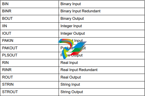
The DCI blocks are configured just like other Foxboro DCS control blocks. The DCI
blocks address and read/write data from/to the addressed field device.
Standard, Rugged Design
The FBM232 has a rugged extruded aluminum exterior for physical and electrical
protection of the circuits. Enclosures, specially designed for mounting the FBMs,
provide various levels of environmental protection, up to Class G3 harsh
environments per ISA Standard S71.04.
Modular Baseplate Mounting
The module mounts on a Modular Baseplate, which accommodates up to four or eight
FBMs. The Modular Baseplate is either DIN rail mounted or rack mounted. The
Modular Baseplate includes signal connectors for the FBMs, provides connections for
independent dc power supplies, I/O cable connections, and 2 Mbps Module Fieldbus
connections.
Easy Removal/Replacement
The module can be removed or replaced without removing power.
Regulatory Compliance,
Product Safety
• Underwriters Laboratories (UL) for U.S. and Canada
UL/UL-C listed as suitable for use in UL/UL-C listed Class I, Groups A-D; Division
2; temperature code T4 enclosure based systems when connected to specified
Foxboro DCS processor modules as described in the Standard and Compact 200
Series Subsystem User’s Guide (B0400FA).
Communications circuits also meet the requirements for Class 2 as defined in
Article 725 of the National Electrical Code (NFPA No.70) and Section 16 of the
Canadian Electrical Code (CSA C22.1). Conditions for use are as specified in the
Standard and Compact 200 Series Subsystem User’s Guide (B0400FA).
• European Low Voltage Directive 2014/35/EU and Explosive Atmospheres (ATEX)
Directive 2014/34/EU
DEMKO certified as Ex nA IIC T4 for use in certified Zone 2 enclosure when
connected to specified processor modules as described in the Standard and
Compact 200 Series Subsystem User’s Guide (B0400FA).
• Marine Certification
ABS Type Approved and Bureau Veritas Marine certified for Environmental
Category EC31.
Calibration
Requirements
Calibration of the module is not required.
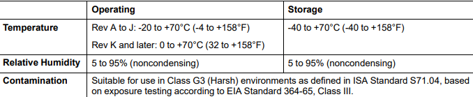
Environmental Specifications
Leave a comment
Your email address will not be published. Required fields are marked *