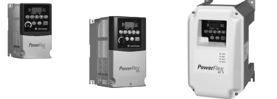
Product Overview
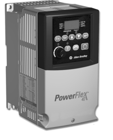
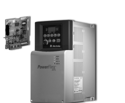
Providing users with powerful motor speed control in a compact, space saving design, the Allen-Bradley® PowerFlex® 4 and
40 AC drives are the smallest and most cost-effective members of the PowerFlex® family of drives. Available in power ratings
from 0.2 to 11 kW (0.25 to 15 HP) and in voltage classes of 120, 240, 480 and 600 volts, PowerFlex 4 and 40 are designed
to meet global OEM and end-user demands for flexibility, space savings, ease of use and are cost-effective alternatives for
speed control of applications such as machine tools, fans, pumps and conveyors and material handling systems
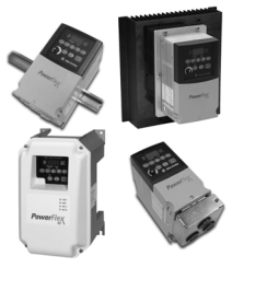
Packaging and Mounting
• Installation can be a virtual snap using the DIN rail mounting feature on
A and B frame drives. Panel mounting is also available, providing added
flexibility.
• Flange mount drives are available to reduce overall enclosure size.
• Zero Stacking™ is allowable for ambient temperatures up to 40 °C, saving
valuable panel space. 50 °C ambient temperatures are permitted with
minimal spacing between drives.
• Integral filtering is available on all 230V single phase ratings, providing a
cost-effective means of meeting EN55011, Class A and B EMC
requirements. External filters provide compliance to Class A and B
requirements for all PowerFlex 4 and 40 ratings.
• An optional IP30, NEMA/UL Type 1 conduit box is easily adapted to
the standard IP20 (NEMA Type Open) product, providing increased
environmental ratings.
• IP66, NEMA/UL Type 4X/12 (Indoor) for mounting directly in the
product environment. Listed by UL to resist dust, dirt, etc. and survive
high pressure water spray. Also certified by NSF to ensure conformity
with international food equipment standards.
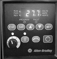
Start Up, Programming and Operation
• An integral keypad provides out of the box operation using the local
potentiometer and control keys.
• The 10 most common application parameters are contained in the Basic
Program Group, making programming fast and easy.
• The programming keys have the same function as all other PowerFlex
drives, so if you can program one PowerFlex drive, you can program them
all.
• 4 digit display with 10 additional LED indicators provides an intuitive
display of drive status and information.
• Integral RS-485 communications can be used for programming from a
PC. It can also be used in a multi-drop network configuration. A serial
converter module provides connectivity to any controller with a DF1
port.
• A NEMA/UL Type 4X remote and NEMA/UL Type 1 hand-held
LCD keypad provide additional programming and control flexibility,
both featuring the popular CopyCat function
Optimized Performance
• Removable MOV to ground provides trouble-free operation when used on ungrounded
distribution systems.
• A relay pre-charge limits inrush current.
• Integral brake transistor, available on all ratings (except no brake version), provides
dynamic braking capability with simple low cost brake resistors.
• DIP switch settable 24V DC sink or source control for control wiring flexibility.
• 150% overload for 60 seconds or 200% overload for 3 seconds provides robust overload
protection.
• Adjustable PWM frequency up to 16 kHz ensures quiet operation.
Sensorless Vector Performance
PowerFlex 4
• Drive automatically provides auto boost (IR
compensation) and slip compensation.
• Provides excellent speed regulation and high levels of
torque across the entire speed range of the drive, and
improved speed regulation even as loading increases.
Sensorless Vector Control
PowerFlex 40
• Sensorless Vector Control provides exceptional speed
regulation and very high levels of torque across the
entire speed range of the drive.
• The Autotune feature allows the PowerFlex 40 to adapt
to individual motor characteristics.
Performance
• This graph depicts the ability of a PowerFlex 40 drive to
accelerate into at least 150% load. A PowerFlex 4 will
perform similarly, but with a slightly higher acceleration
time.
• At 100% motor load, the drive will run the motor at
synchronous speed.
• Excellent current regulation.
• Linear acceleration.
• Best in class digital input response time and
repeatability
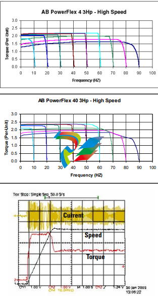
Performance
• Sensorless Vector Control develops high torque over a wide speed range
and adapts to individual motor characteristics.
• Variable PWM allows the drive to output more current at low
frequencies.
• Integral PID functionality enhances application flexibility.
• Timer, Counter, Basic Logic and StepLogic™ functions can reduce
hardware design costs and simplify control schemes.
– Timer function: Relay or opto outputs controlled by drive
performing timer function. Timer is initiated by activating a digital
input programmed as “Timer Start.”
– Counter function: Relay or opto outputs controlled by drive
performing counter function. Counter function is activated by a
digital input programmed as “Counter Input.”
– Basic Logic: Relay or opto outputs controlled by status of digital
inputs programmed as “Logic Inputs.” Performs basic Boolean logic.
– StepLogic: Logic-based steps using preset speed settings. Each step
can be programmed for a specific speed, direction and accel/decel
profile. Drive outputs can be used to indicate which step is being performed.
I/O
• Two (2) Analog Inputs (one unipolar and one bipolar) are
independently isolated from the rest of the drive I/O. These inputs
can be toggled between via a digital input.
• Three (3) fixed and four (4) fully programmable Digital Inputs
provide application versatility.
• One (1) Analog Output is DIP switch selectable for either
0…10V or 0…20mA. This scalable, 10-bit output is suitable for
metering or as a speed reference for another drive.
• Two (2) Opto Outputs and one (1) form C relay output can be
used to indicate various drive, motor or logic conditions.
Communications
• Integral communication cards such as DeviceNet™, EtherNet/IP™,
PROFIBUS™ DP, LonWorks® and, ControlNet™ can improve machine
performance.
• The DSI Wireless Interface Module (WIM) provides a wireless
communication interface between a Pocket PC, laptop computer or
desktop computer equipped with Bluetooth® wireless technology, and any
Allen-Bradley® product supporting the DSI™ protocol.
• Field installed option allows for future addition of stand-alone drives to a
network.
• Online EDS file creation with RS NetWorx™ providing ease of set-up on a
network.
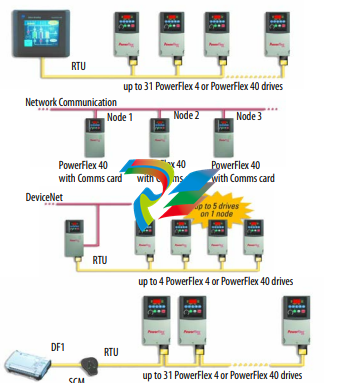
Versatile Programming and Network Solutions
• PowerFlex 4 and PowerFlex 40 are compatible with
any device that acts as a RTU Master and supports
standard 03 and 06 RTU commands.
• A network can be configured using PowerFlex 40
drives with optional communication cards for high
performance and flexible configuration capabilities.
– BACnet
– ControlNet
– DeviceNet
– EtherNet/IP
– LonWorks
– PROFIBUS DP
• A multi-drive solution can be reached using a single
PowerFlex 40 DeviceNet option, with the ability for
up to five drives to reside on one node.
• Integral RS485 communications enable the drives to
be used in a multi-drop network configuration. A
serial converter module (SCM) provides connectivity
to any controller with a DF1 port. The SCM can be
eliminated if the controller acts as a RTU Master.
PC Programming Software
Through the use of a Serial Converter Module and
DriveExplorer™ or DriveTools™ SP software,
programming can be greatly simplified.
DriveExplorer Software
• View and modify drive and adapter parameters in
a method similar to the file management capability
of Microsoft Windows Explorer.
• Operate the drive via an on-screen Control Bar,
which is a tool that allows you to start, stop, and
change the speed reference of the drive.
• Save, restore and print parameter information.
• Compare current parameters with factory defaults
or previously saved parameter values.
• Edit, upload and download parameters.
DriveTools SP Software
• Online and offline programming capability
• In-grid and dialog-based parameter editing
• Immediate visual indication of drive and communication status when viewing online drive
• Integrated HTML Help architecture
Installation Considerations
PowerFlex 4 and 40 drives have the following built in protective features to help simplify installation.
• Ground fault protection while starting and running ensures reliable operation
• Electronic motor overload protection increases motor life
• Removable MOV to ground ensures compatibility with ungrounded systems
• 6kV transient protection provides increased robustness for 380…480V system voltages
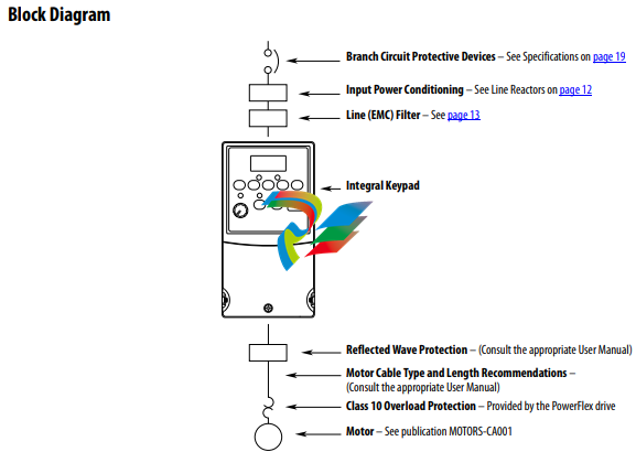
There are many other factors that must be considered for optimal performance in any given application. The block diagram
below highlights the primary installation considerations. Consult the PowerFlex 4 or PowerFlex 40 User Manual,
Publications 22A-UM001 or 22B-UM001 available online at www.rockwellautomation.com/literature, for detailed
recommendations on input power conditioning, CE conformance (EMC filtering), dynamic braking, reflected wave
protection, motor cable types and motor cable distances.
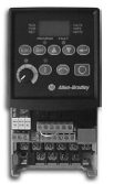
Control Wiring
PowerFlex 4
• The control logic is 24V DC and can be set for either
Sink or Source control via a DIP switch setting.
• Control terminal screws are sized for a conventional
blade screw driver.
• I/O Terminals 1, 2 and 3 are dedicated for Stop, Start
and Reverse operation respectively. These I/O
Terminals can be programmed for 2- or 3-Wire
operation to meet application requirements.
• I/O Terminals 4 and 5 are programmable and provide
added flexibility. Programmable functions include:
– Local Control
– Preset Frequencies
– Jog
– RS485 Control
– Second Accel/Decel
– Auxiliary Fault
– Clear Fault
• Speed can be controlled via a 0…10V input or 4…20
mA input. Both are electrically isolated from the drive.
• One form C relay can be programmed to provide the
status of a wide variety of drive conditions.
• The drive is shipped with a jumper installed between
I/O Terminals 01 and 11 to allow out of box operation
from the keypad.
PowerFlex 40
• The control logic is 24V DC and can be set for either
Sink or Source control via a DIP switch setting.
• Control terminal screws are sized for a conventional
blade screw driver.
• I/O Terminals 1, 2 and 3 are dedicated for Stop, Start and
Reverse operation respectively. These I/O Terminals can
be programmed for 2- or 3-Wire operation to meet
application requirements.
• I/O Terminals 5, 6, 7 and 8 are programmable and
provide added flexibility. Programmable functions
include Local Control, Jog, Second Accel/Decel, Clear
Fault, Preset Frequencies, RS485 Control and Auxiliary
Fault.
• Speed can be controlled via a 0…10V input and/or 4…20
mA input. Both inputs are independently isolated from
the rest of the drive and can be used for applications such
as PID. Voltage input can be programmed for bipolar
operation.
• The drive is shipped with a jumper installed between I/O
Terminals 01 and 11 to allow out of box operation from
the keypad.
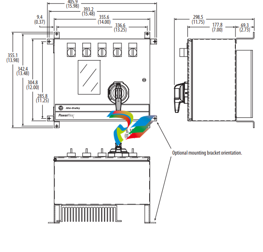
Enclosure Options and Approximate Dimensions
Leave a comment
Your email address will not be published. Required fields are marked *