Safety Summary (continued)
• Process technicians are to be present when testing and operating process
objects.
• Never activate any System Initialization push-button if any uncertainty
exists regarding exactly what occurs within the system during initialization.
ALWAYS CHECK FIRST.
• Remember at all times, that the control system can be controlled from a
remote engineering station, connected at another node via Control
Network.
• Remember, the AC 800M Controller will start automatically when voltage
is applied.
Taking steps to bring the process to a safe state, provides an improved level of
safety when power supplies, communication links or parts of the control system
fail. Such steps may require, for example, the installation of valves or relays that
automatically return to a fail-safe position.
Product Safety
The following safety rules must be observed at all times:
• To avoid discharging static electricity, ground both yourself and any tools
before handling printed circuit boards, batteries, memory cards, and other
sensitive pieces of the equipment
• All electronic devices are sensitive to ESD (electrostatic discharge). To
avoid accidental damage while handling printed circuit boards, it is
recommended to wear a wrist strap, grounded to the chassis. The strap must
have a built-in protective resistor
• Anti-static, conductive plastic bags must be used for storage and transport
of PC boards in transit.
Safety Summary
Before replacing Units
Maintenance
All procedures for replacing units can be located by referring to the relevant
documentation.
Removing or replacing units with system power connected can cause injury to
personnel and damage to equipment. It is, therefore, of the utmost importance
that the power supply be fully disconnected, on the process side, before removal
or insertion of units takes place.
See Online Replacement of Unit on page 198 and I/O documentation.
It is recommended that a stock of suitable spare components be maintained to
avoid system downtime.
Ensure that back-up copies of the current application program are made at
regular, predetermined intervals to avoid system downtime.
Safety Summary (continued)
Operating Environment
Before the AC 800M Controller system is brought online, investigate which
environmental conditions are applicable. Take note in particular of the
following:
• The controller must not be exposed to conditions that exceed the values given
in the relevant technical specifications.
• The controller must not be used in an environment exposed to strong electrical
interference. Electrical machines can produce interference that exceeds levels
permitted for the equipment, for example during repair work.
• All products must be handled with appropriate precautions with regard to
electrostatic damage.
• The controller must not be exposed to direct sunlight.
Important Software Check
• Use the system’s fault-monitoring facilities to prevent accidents or mishaps.
• When in doubt, ALWAYS CHECK before executing changes.
Important Hardware Notice
• DO NOT, under any circumstances, disconnect the power supply to a
normally functioning system. Always use the correct system shut-down
procedure prior to disconnecting the power supply.
Signal Noise Due to Cables
Cables which may cause electrical interference (for example, power supply cables)
must not be installed adjacent to bus cables carrying fast digital signals. Ensure that
a minimum distance of 10 cm (4 in.) is provided between cables installed inside
cabinets.
Hazardous Electrical Supplies
Operational and maintenance procedures, during which personnel may come into
contact with high voltage, should only be carried out by personnel fully trained in
the maintenance of electrical equipment within those environments, and who are
fully aware of all risks involved.
Safety Summary
Electrostatic Sensitive Device
Devices labeled with this symbol require special handling precautions as
described in the installation section.
GENERAL
WARNINGS
Equipment Environment
All components, whether in transportation, operation or storage, must be
in a noncorrosive environment.
Electrical Shock Hazard During Maintenance
Disconnect power or take precautions to insure that contact with energized parts is avoided when servicing.
SPECIFIC
WARNINGS
Page 67: The AC 800M Controller and associated units must be unpowered and disconnected when being mounted onto a DIN-rail!
Page 68: It is not allowed to manipulate CEX bus baseplates in a powered
and running system. Before changing or removing a baseplate, all CEX
modules on that segment must be removed.
Page 72: AC 800M units must be disconnected from the power source
before removing them from a DIN-rail!
Page 72: It is not allowed to manipulate CEX bus baseplates in a powered
and running system. Before changing or removing a baseplate, all CEX
modules on that segment must be removed.
Page 78: For PM861/PM864/PM865/PM866 insert the RCU Link Termination plug TB852, at the RCU Link connector. The termination plug must
always be used for PM861/PM864/PM865/PM866 when running in single
configuration. When a redundant processor is running in a single configuration use the RCU Link Cable TK851, if the RCU Link Termination plug
TB852 is not available.
SPECIFIC
WARNINGS
(continued)
Page 124: The CI862 baseplate has no locking device. Insert only the
CI862 unit into this baseplate. Insertion of other unit types may cause
damage to the equipment.
Page 191: Before attempting maintenance or troubleshooting, read the
Safety Summary on page 13. Failure to do so could lead to personal
injury or damage to equipment.
Page 198: It is not allowed to manipulate CEX bus baseplates in a powered and running system. Before changing or removing a baseplate, all
CEX modules on that segment must be removed.
Page 429: Explosion hazard – Substitution of components may impair
suitability for Class I, Zone 2.
Page 429: Explosion hazard – Do not replace batteries unless the power
has been switched off or the area is known to be non-hazardous.
Page 430: Explosion hazard – Do not disconnect equipment unless the
power has been switched off or the area is known to be non-hazardous.
SPECIFIC
CAUTIONS
Page 68: To prevent damage to the pins, be sure the baseplate plugs and
sockets are fully aligned as the units interconnect. Under no circumstances use excessive force!
Page 68: It is essential that the locking device be placed in the LOCKED
position to avoid possible problems caused by vibration and/or intermittent
grounding.
Page 73: In order to provide adequate access and removal space, note
that the SLIDE sequence must be carried out on the unit baseplates adjacent to the unit that is to be removed.
Page 73: The unit baseplates are easily disconnected from each other by
gently prying them apart with a blade screwdriver (see Figure 23 on page
74).
SPECIFIC
CAUTIONS
(continued)
Page 76: Do not manipulate the locking device. ABB will take no responsibility for errors caused by manipulating locking devices.
-79 and Page 92: Do not place the internal back-up battery in the battery
holder until the AC 800M Controller has been powered-up normally and
the memory back-up function has been activated, that is, the B(attery)
LED flashes. If no normal power supply is connected to the processor unit
with the battery in place, then the CPU memory will immediately start to
consume battery power.
Page 90: Note that in redundant CPU configuration, COM3 and the electrical ModuleBus on the baseplate can not be used.
Page 91: Note that the RCU Link Cable TK851 must be used and can not
be replaced by a similar cable. Using another cable will disable the identification of the CPUs in the CB and Operator Station. When running in single configuration the RCU Link Cable TK851 might temporarily be used to
perform the function of a termination plug.
Page 98: Do not connect the two CEX-Bus segments, separated with
BC810, to each other with CEX-Bus extension cable TK850.
Page 98: In AC 800M High Integrity Controllers it is required that the external supply input of BC810 is connected and that the power supply is
strictly configured either according to Figure 33 or according to Figure 34
and nor is it allowed to change the configuration by way of for instance
individual circuit breakers between modules.
Page 99: Hot swap of the BC810 located next to a primary or single controller CPU, otherwise called “direct BC810”, might jeopardize the whole
controller and should not be performed unless every module on the
CEX-Bus are in a non-operating state. Note: In an AC 800M HI controller
this is unconditionally and intentionally leading to a shutdown of the controller.
Page 112: It is not possible to change the CI851 unit via hot swap and it is
not allowed to perform an online upgrade of firmware in a system containing CI851.
SPECIFIC
CAUTIONS
(continued)
Page 114: It is not possible to change the CI852 unit via hot swap and it is
not allowed to perform an online upgrade of firmware in a system containing CI852.
Page 118: Hot swap is supported for CI854A (not CI854).
Page 133: – 115 V for 110–120 V AC – 230 V for 220–240 V AC
(default position on delivery).
Page 141: To avoid error indications from SA/SB when single power supply is used, it is recommended to connect the input terminals SA/SB on
the CPU to +24 V, see Figure 47.
Page 143: Do not connect the TK821V020 cable until the AC 800M Controller has been powered-up normally and the memory back-up function
has been activated, that is, the B(attery) LED flashes. If no normal power
supply is connected to the PM8xx processor unit, the CPU memory will
immediately start to consume battery power when the cable is connected.
Page 157: When setting the IP address of the primary CPU in Control
Builder, the backup CPU must be turned off (powered down). Otherwise
the backup CPU will take over and you get disconnected.
Page 159: Note that the electrical ModuleBus can only be used for connection of S800 I/O when AC 800M is running in single CPU configuration.
Page 184: Note that a Backup CPU with severe communication errors on
the ModuleBus will be rejected (if ModuleBus is part of the HW configuration) and synchronized state will never be reached as long as error
remains.
Page 189: The RCU Link Cable must NEVER be removed from the primary Processor Unit during redundant operation. Removal of the cable
may cause the unit to stop.
Page 192: Due to the batteries being connected in parallel, it is necessary,
when using the SB821 external battery, to remove the internal battery
from the PM8xx in order to avoid reducing available memory back-up time
Safety Summary
SPECIFIC
CAUTIONS
(continued
Page 195: Due to the batteries being connected in parallel, it is necessary,
when using the SB821 external battery, to remove the internal battery
from the processor unit in order to avoid reducing available memory
back-up time.
-200 and Page 201: Reuse of CPU modules replaced from redundant configurations within the same control network, might cause control network
problems due to the MAC and IP address handling. See MAC and IP
Address Handling in Redundant Configuration on page 49. Such reuse
should not be fulfilled unless both the replaced module and the module
previously acting together with it in redundant configuration are known to
be restored from the previous mutual address swap. It is recommended to
set up an IP-config session and use the “Restore factory settings” option
subsequently followed by reassignment of the IP address or assignment
of a new IP address.
Page 200: Do not, under any circumstances, remove the RCU Link Cable
from the primary CPU now running in a single state. Removing the cable
might cause the CPU to stop.
Page 201: The unit baseplates are easily disconnected from each other by
gently prying them apart with a blade screwdriver (see Figure 23 on page
74).
Page 202: Do not replace the RCU link cable online in a previous version
than 5.0. The support for online replacement also depends on hardware
Product Revision levels. Please consult Release Notes (3BSE021377*)
for detailed information.
Page 428: If you use other power supplies, except SD82X and SD83X, to
provide the 24V d.c. for AC 800M it is required that they also are CE
marked, Underwriters Laboratories (UL ) listed and fulfill the LVD (SELVandPELV) criteria.
Page 428: The AC 800M modules are IP20 semi-protected equipment and
must be mounted in non-public localities.
About This User Manual
General
This book describes the hardware platform AC 800M. It also describes in detail how
to install, configure, operate and perform the necessary maintenance on all
equipment making up the AC 800M or AC 800M HI controllers.
Control Builder is used to configure and program the AC 800M controller, and is
referred to in this manual as Control Builder. For information on the controller
software, see controller software documentation.
For important information about late changes and work-arounds for known
problems, refer to the Release Notes (see Released User Manuals and Release Notes
on page 28).
User Manual Conventions
Microsoft Windows conventions are normally used for the standard presentation of
material when entering text, key sequences, prompts, messages, menu items, screen
elements, etc.
Any security measures described in this User Manual, for example, for user
access, password security, network security, firewalls, virus protection, etc.,
represent possible steps that a user of an 800xA System may want to consider
based on a risk assessment for a particular application and installation. This risk
assessment, as well as the proper implementation, configuration, installation,
operation, administration, and maintenance of all relevant security related
equipment, software, and procedures, are the responsibility of the user of the
800xA System
Warning, Caution, Information, and Tip Icons
This publication includes Warning, Caution, and Information where appropriate
to point out safety related or other important information. It also includes Tip to
point out useful hints to the reader. The corresponding symbols should be
interpreted as follows:
Although Warning hazards are related to personal injury, and Caution hazards are
associated with equipment or property damage, it should be understood that
operation of damaged equipment could, under certain operational conditions, result
in degraded process performance leading to personal injury or death. Therefore,
fully comply with all Warning and Caution notices.
Terminology
A complete and comprehensive list of terms is included in System 800xA System
Guide Functional Description (3BSE038018*). The listing includes terms and
definitions that apply to the 800xA System where the usage is different from
commonly accepted industry standard definitions and definitions given in standard
dictionaries such as Webster’s Dictionary of Computer Terms.
Electrical warning icon indicates the presence of a hazard which could result in
electrical shock.
Warning icon indicates the presence of a hazard which could result in personal
injury.
Caution icon indicates important information or warning related to the concept
discussed in the text. It might indicate the presence of a hazard which could
result in corruption of software or damage to equipment/property.
Information icon alerts the reader to pertinent facts and conditions.
Tip icon indicates advice on, for example, how to design your project or how to
use a certain function
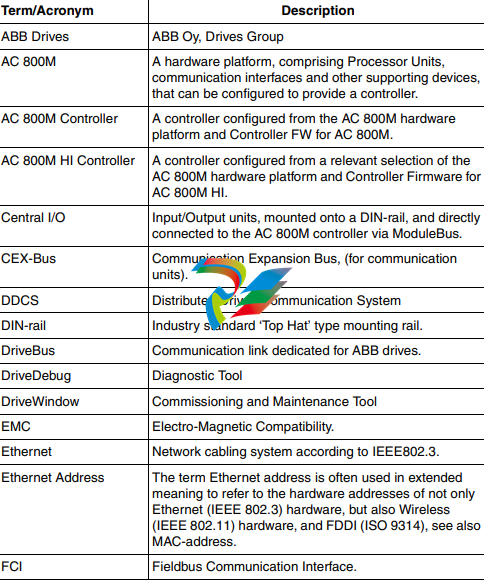
Terms that uniquely apply to this User Manual are listed in the following table.
Table 1. Terminology
UL requirements for hazardous locations, the instructions in Appendix E, Standards
must be followed.
TÜV Approval
Units mentioned in this document are TÜV qualified for IEC 61508 SIL2 or SIL3 if
the
product is marked with the TÜV logo.
Released User Manuals and Release Notes
A complete list of all User Manuals and Release Notes applicable to System 800xA
is provided in System 800xA Released User Manuals and Release Notes
(3BUA000263*).
System 800xA Released User Manuals and Release Notes (3BUA000263*) is
updated each time a document is updated or a new document is released. It is in pdf
format and is provided in the following ways:
• Included on the documentation media provided with the system and published
to ABB SolutionsBank when released as part of a major or minor release,
Service Pack, Feature Pack, or System Revision.
• Published to ABB SolutionsBank when a User Manual or Release Note is
updated in between any of the release cycles listed in the first bullet.
A product bulletin is published each time System 800xA Released User Manuals
and Release Notes (3BUA000263*) is updated and published to ABB
SolutionsBank.
Product Overview
AC 800M – General
AC 800M is a hardware platform comprising individual hardware units, which can
be configured and programmed to perform multiple functions.
Once configured and programmed, the AC 800M effectively becomes the AC 800M
or AC 800M HI controller.
The hardware units that form the AC 800M and AC 800M HI Controllers are:
• Processor units (including baseplate)
(PM851/PM851A/PM856/PM856A/PM860/PM860A/PM861/PM861A/
PM864/PM864A/PM865/PM866/PM891)
• High Integrity Processor Unit
(consists of PM865 and SM810/SM811 with corresponding baseplates)
• Communication interfaces for different protocols (including baseplates)
(CI851/CI852/CI853/CI854/CI854A/CI855/CI856/CI857/CI858/CI860/
CI862/CI865/CI867/CI868/CI869/CI871/CI872/CI873)
• CEX-Bus Interconnection Unit
(BC810)
• Power supply units, providing various power output levels
SD831/SD832/SD833/SD834/SS823/SS832)
• Battery back-up unit
(SB821/SB822)
The SB821 is not supported with PM891.
PM851 is equivalent with PM856 unless stated otherwise.
PM851A is equivalent with PM851 unless stated otherwise.
PM856A is equivalent with PM856 unless stated otherwise.
PM860A is equivalent with PM860 unless stated otherwise
PM861A is equivalent to PM861 unless stated otherwise.
PM864A is equivalent to PM864 unless stated otherwise
When equipped with the specified Control Software, the AC 800M Controller acts
either as a stand-alone process controller, or as a controller performing local control
tasks in a control network consisting of many interconnected controllers, operator
stations and servers.
Various I/O systems can be connected to the AC 800M Controller, either directly
(S800 I/O) or via PROFIBUS DP or FOUNDATION Fieldbus.
The AC 800M is delivered without Control Software. To provide the controller
with Control Software, first load the firmware and then create the application
separately using the Control Builder M engineering tool.
The AC 800M Controller consists of a selection of units mounted on horizontal
DIN-rails, which can be housed within an enclosure. The majority of units consist of
a base mounting plate and removable cover attached with screws.
The baseplate, which is always mounted onto the DIN-rail, carries the majority of
the connections to processor, power supplies and communication interfaces, as well
as the connections to the external buses and systems.
The AC 800M Controller provides a cost-effective, low-maintenance solution for
applications ranging from small Programmable Logic Controller (PLC) to advanced
Distributed Control Systems (DCS) control applications and combined DCS, and
High Integrity systems control applications.
In the AC 800M High Integrity Controller, it is possible to run both non-SIL and
SIL classified applications. The AC 800M HI consist of PM865, SM810/SM811
and a High Integrity version of Control Software, and is also available in redundant
configuration. AC 800M HI requires the use of SIL certified S800 I/O units in SIL
classified applications. If the application is not SIL classified, standard S800 I/O
units can be used with AC 800M HI controller.
Figure 1 shows the physical appearance of an AC 800M Controller with an
S800 I/O Unit. This physical appearance does not apply to PM891.
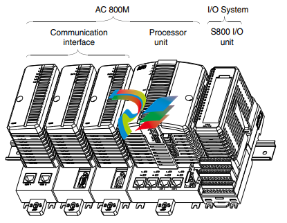
Figure 1. Example of an AC 800M Controller (except PM891) with an S800 I/O
Unit
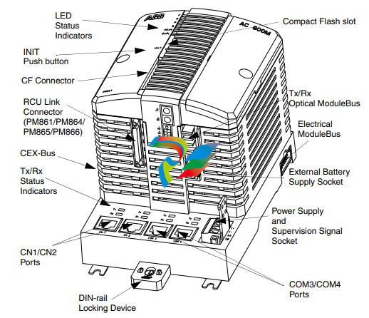
shows the PM861 processor unit that is part of the AC 800M controller.
This processor unit is different from PM891.
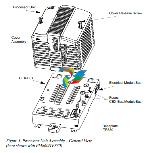
PM8xx/TP830 Processor Unit – General
Physically the PM8xx/TP830 Processor Unit consists of two basic parts:
• Processor Unit
(PM851/PM851A/PM856/PM856A/PM860/PM860A/PM861/PM861A/
PM864/PM864A/PM865/PM866) with processor and Power Supply boards.
• Baseplate (TP830), housing the unit termination board.
For the Functional Block Diagram, see Figure 4 on page 35 and
Figure 5 on page 36. The CPU board contains the microprocessor and the RAMmemory, controllers for all built-in communication interfaces, real-time clock, LED
indicators, INIT push button and a Compact Flash interface.
The main function of the power supply board is to generate isolated, circuit-proof
+5 V and +3.3 V supplies to the CPU and I/O units. The board also contains optoisolated RS-232C drivers/receivers for the service port, together with a back-up
battery holder for memory/real time clock, (RTC).
The termination board, housed in the TP830 Baseplate, is where the majority of
the external connections terminates. The board is grounded to the DIN-rail through
of the metallic components of the housing. The termination board is provided with
screw terminals for power supply and redundant power supply monitoring, with
RJ45 connectors for the control network and serial port, a connector for the service
port, the electrical ModuleBus and the CEX-Bus.
The 24 V DC supply, connected to the TP830 Baseplate, powers all the units on the
CEX-Bus and the electrical ModuleBus.
In single CPU configuration, it is possible to connect an S800 I/O cluster directly to
the built-in electrical ModuleBus plug located on the right hand side of the TP830
Baseplate.
The processor unit has a communication expansion bus connector located on
the left-hand side of the TP830 Baseplate. This CEX-Bus provides for extending
the on-board communication ports with additional communication interfaces
PROFIBUS DP, FOUNDATION Fieldbus H1, FOUNDATION Fieldbus High Speed
Ethernet and dual RS-232C ports are some examples of unit types available for
connection to the CEX-Bus. It is possible to use redundant communication
interfaces, for example PROFIBUS DP.
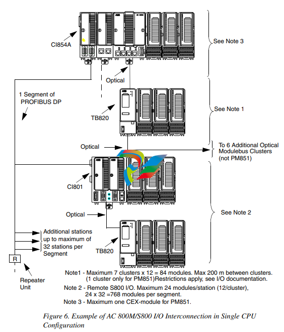
Figure 6 on page 38 provides examples of various ways to connect the S800 I/O
units. It can be seen, at the top right-hand area of Figure 6 on page 38, that one
cluster (or group) of units (maximum number of units per cluster is 12) is connected
to the electrical ModuleBus of an AC 800M Controller. However, a further seven
clusters (each comprising up to 12 units) can be added to the optical ModuleBus,
thus achieving a total count of 96 units per AC 800M Controller when using only
the ModuleBus.
To the left on Figure 6 on page 38, there is a PROFIBUS DP segment. This allows
for a large increase in the numbers of units connected to each AC 800M Controller.
Here the segment is shown as having an FCI unit (type CI801), connected to the
PROFIBUS DP network. The use of FCI units allows the selection of units from
several I/O families.
Figure 7 on page 39 shows another example for I/O units based on a
FOUNDATION Fieldbus High Speed Ethernet (FF HSE).
For further examples refer to the relevant documentation for the I/O system in
question.
Connecting S800 I/O units (using the ModuleBus) to an AC 800M Controller
mounted with a PM851/PM851A processor unit is restricted to, one electrical
ModuleBus cluster and one optical ModuleBus cluster
PM891 Processor Unit – General
PM891 is a high performance controller, which is capable of handling applications
with high requirements.
PM891 connects to the S800 I/O system through the optical Modulebus. It can act
as a stand-alone Process Controller, or as a controller performing local control tasks
in a control network.
Two PM891 controllers can function together as a redundant pair, with one PM891
acting as the primary controller and the other acting as the backup. The backup
controller takes over the process controller tasks if any hardware error occurs in the
primary controller.
The control network connectivity is obtained by two built in IEEE802.3 Ethernet
channels on PM891.
PM891 also provides a communication expansion bus (CEX-Bus) to which a
number of expansion modules can be connected. These modules offers connectivity
to a wide range of field bus and I/O systems. In case of a redundant pair, both
PM891s are connected to the same CEX-Bus and one of them can control the
modules.
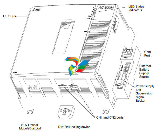
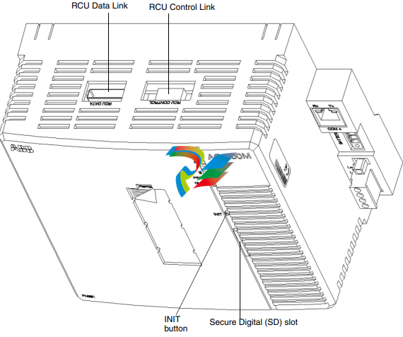
Physically, the PM891 Processor Unit consists of:
• Connector for power supply and status signals (L+, L-, SA, SB).
• DB25 connector for Electrical CEX-Bus.
• External battery connector.
• RJ45 connectors for the two Ethernet channels.
• One Com port.
• Optical Modulebus connector for connection to a maximum of seven clusters,
with 12 non-redundant or six redundant modules (that is, 7×12 = 84 modules).
• Connectors for Redundancy Link.
• SD (Secure Digital) memory connector.
• LEDs.
• Pushbutton reset switch.
shows the front view, Figure 9 shows the top view, and Figure 10 shows the
bottom view of PM891.
Screw terminals are provided for connections to the power supply and the external
battery.
The 24 V DC power supply powers all the units on the CEX-Bus. The optical
module clusters are powered independently.
PM891/PM86x/TP830 Processor Unit – Redundancy
Processor unit redundancy is available for PM861, PM864, PM865, PM866, and
PM891. In this case, the controller contains two processor units, each including
memory for system and application software. One unit is acting as primary, the
other is backup (hot stand-by). The primary processor unit controls the process. The
backup stands by, ready to take over in case of a fault in the primary. The
changeover is done bumplessly and in less than 10 ms. During the changeover, the
process outputs are frozen.
Following a changeover, the system operates as a system without redundancy with
only one processor unit in operation. You can replace the malfunctioning processor
unit while the system is running. After the replacement is carried out, the system
once again has a redundant processor unit.
If an error arises in the backup unit, you can also replace the backup unit while the
system is running.
Errors which occur in the backup unit can never affect the primary unit’s operation.
The primary unit and the backup unit are logically separated from one another.
Hardware errors in the primary processor unit cause the system to perform a correct
changeover. These hardware errors are single errors.
The application programming and the communication are totally unaffected by the
redundancy.
PM86x/TP830 Redundancy
The PM861/PM864/PM865/PM866 has an RCU Link Connector for connecting the
RCU Link Cable (see Figure 2 on page 32). In a redundant system the two processor
units are linked together with the RCU Link Cable (max 1 m). Both processor units
are also connected to the same CEX-Bus and either of the two can control the
expansion units (see Figure 29 on page 93).
S800 I/O units are connected to the two CPUs via the optical ModuleBus and two
TB840 cluster modems on each S800 I/O cluster (see Figure 55 on page 161). The
built-in electrical ModuleBus on the TP830 baseplate cannot be used for connecting
S800 I/O in a redundant system.
The serial port, COM3 on the baseplate TP830, cannot be used in redundant CPU
configuration.

Leave a comment
Your email address will not be published. Required fields are marked *