Call us 24/7+86 15396210640
Welcome to the official website of Lingkong Automation Technology Co., Ltd!
Call us 24/7+86 15396210640

parkerRack power supply unit

» From the Vibro-Meter ® product line

» Power supply unit for VM600 system rack (6U)

» High performance

» Wide input voltage range

» Over-voltage protection

» Continuous short-circuit proof

» Minimal derating within the operating

temperature range

» 6U height

» Compact design

» Fully VME compatible

» Conforms to EC standards for EMC

» Up to two RPS6U rack power supply units can be 

installed in a VM600 system rack (ABE04x)

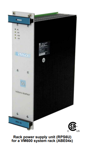
Rack power supply unit (RPS6U)

for a VM600 system rack (ABE04x)

DESCRIPTION

The RPS6U rack power supply units are designed for 

use in the VM600 series of machinery protection 

systems and condition and performance monitoring 

systems, from Meggitt Sensing Systems’ Vibro-Meter 

product line.

The RPS6U is installed in the front of a VM600 

system rack (ABE04x) with a standard height of 6U 

and connects directly to the rack backplane via two 

connectors. The power supply provides +5 VDC and 

±12 VDC power to all cards in the rack via the rack 

backplane.

One or two RPS6U power supplies can be installed in 

a VM600 system rack. A rack can have two RPS6U 

units installed for different reasons: to supply power to 

a rack with many cards installed, non-redundantly, or 

to supply power to a rack with fewer cards installed, 

redundantly. Typically, the cutoff point is when nine 

rack slots or fewer are used

Rack power supply unit

RPS6U

2 / 15 © Meggitt SA / 268-011 / Version 9 / 23.04.2015 / E

DESCRIPTION (continued)

When a VM600 system rack is operating with two 

RPS6U units for power supply redundancy, if one 

RPS6U fails, the other will provide 100% of the power 

requirement and the rack will continue to operate, 

thereby increasing the availability of the machinery 

monitoring system.

Various versions of the RPS6U exist, allowing a rack 

to be powered from external AC or DC mains supplies 

with a range of supply voltages.

A power supply check relay, available at the rear of a 

VM600 rack, indicates that the power supplies are 

operating normally. Refer to the ABE040 and ABE042 

VM600 system rack and ABE056 VM600 slimline 

rack data sheets for additional information on power 

supply check relays.

In applications where the VM600 rack is powered by 

an AC mains supply, an auxiliary sensor power supply 

(ASPS) can also be included in the rack. The ASPS 

provides +24 VDC outputs which can be used by 

external hardware such as front-end transducers, 

signal conditioners and galvanic separation units.

For specific applications, contact your nearest Meggitt 

Sensing Systems representative.

SPECIFICATIONS

Power supply

Input

Input voltage range (Vi

 nom.) : See Ordering information on page 12

Mains frequency variations : See Ordering information on page 12

Efficiency : See Ordering information on page 12

Output

Nominal output (Vo nom. / Io max.)

• DC output 1 : +5 VDC / +35 A

• DC output 2 : +12 VDC / +6 A

• DC output 3 : −12 VDC / −2 A

Stability of output voltage Uo

under full load conditions

: ≤ ±0.2%

Ripple (bandwidth 20 MHz) : ≤ 50 mVpp

Output current limitation : 35 A (electronic current limiter)

Output overvoltage protection : 5.9 to 6.7 V (factory set)

Power derating : 1%/°C from 60 to 70°C

Power

Rated power : 300 W

Rated supply voltage : See Ordering information on page 12

Environmental

According to IEC 60068-2 recommendations

Operating temperature range : −25 to +65°C (−13 to +149°F)

Storage temperature range : −40 to +85°C (−40 to +185°F)

Humidity : ≤ 95% non-condensing

Vibration : 10 to 2000 Hz, 5 g, 2 h in each direction

Shock : 100 g, 6 ms, half-sine pulse

Physical

Dimensions : 6 U / 12 HP (TE) x 187 mm

Weight (approx.) : 2.1 kg (4.63 lb) 

Safety

Applicable safety standards : UL 1950, CSA 22.2#234, IEC 950, EN 60950

Marking : See Ordering information on page 12

TOLERANCE TO MICRO-INTERRUPTIONS IN THE SUPPLY INPUT

The table below shows the maximum permissible duration of a power cut which will not cause MPC4 cards to be reset. 

This value depends on the number of MPC4 cards and RPS6U units installed in the VM600 rack.

Number of RPS6U power supplies in VM600 system rack

Number of MPC4 cards in

VM600 system rack

1 unit 2 units

2 cards 190 ms 250 ms

12 cards 10 ms 20 ms

S

ORDERING INFORMATION (continued)

Rear panels

To order please specify the type (Rear panel), designation and ordering number from the table below

(see also the drawings (a) to (k) in Associated rear panels on pages 4 to 9)

Drawing Designation Ordering number

(a)

One DC input with screw-terminal connector that provides a common input to the

RPS6U power supplies.

This rear panel is equivalent to Rear panel for RPS6U power supply order option code F200.

200-582-920-NHh

(b)

Two DC inputs with screw-terminal connectors that provide individual inputs to the

RPS6U power supplies.

This rear panel is equivalent to Rear panel for RPS6U power supply order option code F930.

200-582-993-NHh

(c)

One DC input with screw-terminal connector that provides a common input to the

RPS6U power supplies. Also provides a special earth terminal (identified as M.A.L.T.).

This rear panel is equivalent to Rear panel for RPS6U power supply order option code F220.

200-582-922-NHh

(d)

Two DC inputs with screw-terminal connectors that provide a common input to the

RPS6U power supplies.

Supports redundant external power-supply systems.

This rear panel is equivalent to Rear panel for RPS6U power supply order option code F900.

200-582-990-NHh

(e)

One AC input (120/230 VAC) with mains socket and on/off switch that provides a common 

input to the RPS6U power supplies.

This rear panel is equivalent to Rear panel for RPS6U power supply order option code F100.

200-582-910-NHh

(f)

One AC input (120/230 VAC) with screw-terminal connector, on/off switch and rear-panel fuses 

that provides a common input to the RPS6U power supplies.

This rear panel is equivalent to Rear panel for RPS6U power supply order option code F110.

200-582-911-NHh

(g)

One AC input (120/230 VAC) with screw-terminal connector and rear-panel fuses that provides 

a common input to the RPS6U power supplies.

This rear panel is equivalent to Rear panel for RPS6U power supply order option code F120.

200-582-912-NHh

(h)

Two AC inputs (120 VAC only) with mains sockets and on/off switches that provide a common 

input to the RPS6U power supplies.

Supports redundant external power-supply systems.

This rear panel is equivalent to Rear panel for RPS6U power supply order option code F620.

200-582-962-NHh

(i)

Two AC inputs (120/230 VAC) with mains sockets and on/off switches that provide individual 

inputs to the RPS6U power supplies.

This rear panel is equivalent to Rear panel for RPS6U power supply order option code F630.

200-582-963-NHh

(j)

Two AC inputs (230 VAC only) with mains sockets and on/off switches that provide a common 

input to the RPS6U power supplies.

Supports redundant external power-supply systems.

This rear panel is equivalent to Rear panel for RPS6U power supply order option code F600.

200-582-960-NHh

(k)

Two AC inputs (120/230 VAC) with screw-terminal connectors, on/off switches and rear-panel 

fuses that provide individual inputs to the RPS6U power supplies.

This rear panel is equivalent to Rear panel for RPS6U power supply order option code F150.

200-582-915-NHh

(l)

Two AC inputs (120/230 VAC) with screw-terminal connectors and rear-panel fuses that 

provide individual inputs to the RPS6U power supplies.

This rear panel is equivalent to Rear panel for RPS6U power supply order option code F160.

200-582-916-NHh

(m)

One AC input (120/230 VAC) with mains socket and on/off switch and one DC input with screwterminal connector that provide individual inputs to the RPS6U power supplies.

This rear panel is equivalent to Rear panel for RPS6U power supply order option code F700.

200-582-970-NHh

Rack power supply unit

RPS6U

14 / 15 © Meggitt SA / 268-011 / Version 9 / 23.04.2015 / E

Notes

All AC input rear panels are supplied with a mains power supply lead (no lead is supplied for the DC input versions). See Mains power 

supply leads (power cords) on page 14.

AC input rear panels with mains sockets have an IEC type C14 connector (IEC 60320) that mates with the plug (type C13) used by the 

supplied mains power supply leads.

Rear panels with one input – (a), (b), (c), (d), (e), (f) and (g) – are 2 slots wide / 8 HP (TE).

Most rear panels with two inputs – (h), (i), (j), (k) and (l) – are 4 slots wide / 16 HP (TE).

However, the rear panel with AC and DC inputs – (m) is 2 slots wide / 8 HP (TE).

(The width of 19″ rack is measured in horizontal pitch (HP) units of 5.08 mm (0.2″), also known as standard width (TE) units. For the 

ABE04x rack, a one slot wide (one card position) blank panel corresponds to 4 HP (TE), a two slot wide blank panel corresponds to 8 HP (TE) 

and a four slot wide blank panel corresponds to 16 HP (TE).)

Rear panels with two input connectors that provide a common input to the RPS6U power supplies – (d), (h) and (j) – installed in the rack can 

be used with a redundant external power-supply system.

For additional information on the Rear panel for RPS6U power supply order option codes (Fxxx), refer to the ABE040 and ABE042 VM600 

system rack and ABE056 VM600 slimline rack data sheets.

For the Ordering number:

“NHh” represents the hardware version.

“N” is either “0” for a rear panel according to (and marked) CE low voltage directive or “2” for a rear panel according to (and marked) CCSAUS.

“H” increments are for major modifications that can affect product interchangeability.

“h” increments are for minor modifications that have no effect on interchangeability

Mains power supply leads (power cords)

To order please specify the type (Mains power supply lead), designation and ordering number from the table below

Designation Ordering number

None – no mains cable.

This rear panel is equivalent to Mains power supply lead (power cord) order option code H00. —

No plug – flying lead with wire-end ferrules.

This rear panel is equivalent to Mains power supply lead (power cord) order option code H01. 957.18.13.0020

J plug as per SEV 1011 (Switzerland).

This rear panel is equivalent to Mains power supply lead (power cord) order option code HCH. 957.18.13.0021

E+F plug as per CEE7/VII (Europe, Russia, Ukraine).

This rear panel is equivalent to Mains power supply lead (power cord) order option code HEU. 957.18.13.0022

G plug as per BS 1363 (UK, Hong Kong, Malaysia, Singapore).

This rear panel is equivalent to Mains power supply lead (power cord) order option code HUK. 957.18.13.0023

B plug as per JIS 8303 (Japan).

This rear panel is equivalent to Mains power supply lead (power cord) order option code HJP. 957.18.13.0024

B plug as per NEMA 5-15 (United States, Canada).

This rear panel is equivalent to Mains power supply lead (power cord) order option code HUS. 957.18.13.0025

Notes

The mains cables (power cords) are for the AC input version of the RPS6U power supply. No cables are available for the DC input versions.

Rear panels with two AC inputs for independent mains supplies (ordering numbers: 200-582-96x-NHh) require two mains cables.

For additional information on the Mains power supply lead (power cord) order option codes (Hxx), refer to the ABE040 and ABE042 VM600 

system rack and ABE056 VM600 slimline rack data sheets.

Headquartered in the UK, Meggitt PLC is a global engineering group specializing in extreme environment components and smart sub-systems for aerospace, 

defence and energy markets.

Meggitt Sensing Systems is the operating division of Meggitt specializing in sensing and monitoring systems, which has operated through its antecedents since 1927 

under the names of ECET, Endevco, Ferroperm Piezoceramics, Lodge Ignition, Sensorex, Vibro-Meter and Wilcoxon Research. Today, these operations are 

integrated under one strategic business unit called Meggitt Sensing Systems, headquartered in Switzerland and providing complete systems, using these renowned 

brands, from a single supply base.

The Meggitt Sensing Systems facility in Fribourg, Switzerland was formerly known as Vibro-Meter SA, but is now Meggitt SA. This site produces a wide range of 

vibration and dynamic pressure sensors capable of operation in extreme environments, leading-edge microwave sensors, electronics monitoring systems and 

innovative software for aerospace and land-based turbo-machinery.

All statements, technical information, drawings, performance rates and descriptions in this document, whilst stated in good faith, are issued for the sole 

purpose of giving an approximate indication of the products described in them, and are not binding on Meggitt SA unless expressly agreed in writing. 

Before acquiring this product, you must evaluate it and determine if it is suitable for your intended application. Unless otherwise expressly agreed in 

writing with Meggitt SA, you assume all risks and liability associated with its use. Any recommendations and advice given without charge, whilst given in 

good faith, are not binding on Meggitt SA.

Meggitt Sensing Systems takes no responsibility for any statements related to the product which are not contained in a current Meggitt Sensing Systems 

publication, nor for any statements contained in extracts, summaries, translations or any other documents not authored by Meggitt Sensing Systems. We 

reserve the right to alter any part of this publication without prior notice.

In this publication, a dot (.) is used as the decimal separator and thousands are separated by thin spaces. Example: 12 345.678 90.

Condition monitoring system (CMS) software for the VM600 series

From the Vibro-Meter® product line

» Configuration and operation of VM600 

hardware (CMC16 and IOC16T condition 

monitoring card pairs)

» Automatic data acquisition and storage

» Limit exceedance checking and 

event logging

» Online or offline data analysis

» Graphical user interface

» Runs on Windows® Server 2003, 

Windows NT, Windows 2000, Windows XP, 

Windows Vista and Windows 7 operating 

systems

» ANSI SQL-92 compatible

» Optional modules:

Air Gap Module for hydro-turbines

Diagnostics Rule Box

DESCRIPTION

Condition-based maintenance is a predictive 

methodology that can be used to improve your asset 

(machinery) effectiveness. It enables you to:

• Improve equipment reliability through the effective 

 prediction of equipment failures

• Minimise downtime through the planning and 

 scheduling of overhauls

• Maximise component life by avoiding critical known 

 conditions

• Utilise condition monitoring techniques to maximise 

 equipment performance.

The VM600 CMS Software from Meggitt Sensing 

Systems’ Vibro-Meter ® product line is based on this 

principle and is dedicated to the support of technicians, 

operators and engineers, enabling them to identify a 

problem rapidly, evaluate the situation and determine the 

appropriate action to take.

The VM600 CMS Software has a truly modular 

architecture that adapts to your specific needs. It 

comprises several software modules for use with the 

VM600 series hardware

To use the VM600 CMS Software, the system 

parameters are configured (once) before the data 

acquisition and signal processing starts. Then the results 

can be displayed as required, to assist the advanced 

analysis and diagnosis of the monitored machinery.

The VM600 CMS Software has the ability to 

automatically adapt to the criticality of the machine 

status by applying specific data logging scenarios. The 

background mode is continuous low-resolution data 

acquisition. The scheduled mode is pre-defined highresolution acquisition. The transient mode is 

automatically detected and then transient data are 

acquired when the speed is out of the “steady” state. 

Finally, the manual mode is real-time data acquisition 

initiated by the user.

The VM600 CMS Software takes advantage of the 

industry standard platforms to allow total adaptability of 

the system. It runs under Windows Server 2003, 

Windows NT, Windows 2000, Windows XP, 

Windows Vista and Windows 7 and has a fully graphical 

interface for ease of use. Moreover, the SQL-based data 

management server allows you to communicate with any 

other SQL-based database.

The VM600 CMS Software can run on a single host 

computer or on a number of systems connected to the 

VM600 rack by network connections. This lets you 

decide whether you need to perform the entire 

configuration, acquisition, data analysis and 

troubleshooting tasks from one location or distribute 

them among several workstations. In a distributed 

configuration, all specific functions can be performed on 

dedicated computers by appropriate personnel. This 

classification also enables remote data collection and/or 

analysis, and means that configuration and 

troubleshooting tasks can be performed via remote 

access if necessary. 

For further applications, the VM600 CMS Software 

provides a suite of standard import/export interfaces, 

enabling you to transfer data to/from any third-party 

system. Your installation benefits are thus the full 

flexibility and scalability of the system, because it 

enables the correlation of vibration data with other 

parameters that are already available from other 

devices, so there is no need to re-measure. The 

available interfaces are Modbus and OPC (open 

connectivity) for communication with field devices such 

as PLDs (programmable logic devices) and DCSs 

(distributed control systems). The Microsoft ® DDE 

(dynamic data exchange) standard is used to exchange 

data between the VM600 CMS Software and external 

devices. Finally, the ODBC (open database connectivity) 

allows your VM600 CMS database to import data from 

any ODBC database.

On top of these modules, the Diagnostics Rule Box 

enables the user to integrate his machinery knowledge 

within the program rules, set conditions on real-time 

values, create alarms and alerts, and ultimately generate 

automatic actions to adequately warn the user if an 

event occurs.

Figure 1: VM600 CMS system architecture – the relationship between the computers running VM600 CMS

and the underlying VM600 hardwar

Figure 2: VM600 CMS Software architecture – the relationship between the VM600 CMS Software application modules, 

external interfaces and the underlying VM600 hardware

VM600 condition monitoring system software

CMS

4 / 12 © Meggitt SA / 268-106 / Version 4 / 02.10.2012 / E

SOFTWARE MODULES

The software application modules that make up the VM600 CMS Software client-server architecture are as shown in 

Table 1 (below).

VM600 Administrator The VM600 Administrator program is a portal (window) that provides quick and convenient 

access to all of the VM600 CMS Software tools, as well as to a number of useful Windows 

system tools.

Mimic The Mimic provides the operator with a customised, graphical view of the machinery being 

monitored by the VM600 CMS Software system.

The types of data you can visualise directly from the Mimic are “live” data, that is, current 

values and current status of both the VM600 hardware and the “offline” systems, as well as 

user-requested high-resolution data such as waveforms, spectra and orbit plots. 

Configuration Editor The Configuration Editor is used to set up the required configuration of all parameters of the 

system, including the configuration details of each single output band, machine-specific 

parameters for data logging or transient data and complete VM600 rack configurations. 

It stores the system configuration inside the SQL database, from where it can be viewed or 

changed by users with sufficient access rights. 

It is also a starting point for the advanced configuration of the database, such as preparing 

the database to accept “offline” data imported from external systems.

Data Analyser The Data Analyser is used to display measurement data from the SQL database. 

It takes data from selected data points defined in the database, applies user- or systemdefined filters to the data, and displays the data as a variety of graphs, plots and charts.

Typical filters that can be applied to data are time, alarm status, machine status, or a userconfigurable filter based on any speed, analog or digital data.

Database Browser The Database Browser is used to display the content of the SQL database in graphical 

form. 

It can display stored datasets, such as events, spectra, waveforms and orbits as intuitive 

time-line representations, thus providing an effective overview of the measurement data 

that have been collected. You can then quickly navigate to the dataset of interest using a set 

of independent criteria (by point, type of data set, time or alarm state).

Event Viewer The Event Viewer is used to view the events in the SQL database that may have been 

created automatically by the system or as defined by users. It displays the available events 

in list form, using colour coded, intuitive icons. The window shows either all events present 

in the database, or you can choose to set and activate filter criteria in order to limit the 

displayed events. 

VMCom

Communications Handler

The VMCom program handles the flow of data between VM600 racks and SQL databases. 

It communicates with the VM600 CMS hardware and the SQL database. 

This program can either be launched manually or configured as a system service, for which 

purpose a special service setup utility is included that allows you to configure, create or 

delete a Windows service. This is the preferred way of communicating with VM600 

hardware for permanent system installations and dedicated on-line condition monitoring 

applications.

Table 1: VM600 CMS Software application modules

parkerVM600 systems: Integrated machinery protection, condition and performance monitoring

Why monitor your machinery ?

Monitoring is fundamental to Plant Asset Management.

Whether your business is in the power generation, oil

and gas or petrochemical industry, understanding the

mechanical behaviour of rotating machinery brings you

the following benefits:

Safety

Monitoring systems help avoid catastrophic failures

and unplanned outages, protecting your personnel and

your investment.

Return on assets

The financial return delivered by your physical assets

is increased. Monitoring systems help you maximize

the overall productivity of your turbomachinery

through:

• Higher availability (reduced outages,

maintenance optimization)

• Improved machine efficiency

• Lower spare parts inventory and maintenance costs

Emissions and environment

Our performance and emissions monitoring functions

help to reduce fuel consumption as well as CO2 and

NOX emissions, in order to comply with environmental

regulations.

Why choose VM600 

integrated solution ?

One single expandable platform

Vibro-Meter’s VM600 platform truly integrates all protection,

condition and performance monitoring functions in a single

system. It is easily expandable and does not require

additional internal wiring.

One module does all

We are pioneers with our solution based on single modules

processing all parameters (vibration, velocity, displacement,

dynamic pressure, temperature, etc…) used for protection

and condition monitoring.

When you need a new function, it is already included in the

module in your system.

High reliability

All modules are independent and separately protected; they allow continuous system operation

if one has to be replaced. The VM600 has dual, crossed redundancy between power modules

and mains lines, allowing true power supply redundancy.

One source

Request a complete solution from Vibro-Meter! In our Fribourg headquarters (Switzerland),

more than 550 employees combine their expertise and commitment to designing and building

all parts of your system: Sensors for harsh environments (measuring vibration, dynamic

pressure, displacement…), high performance monitoring systems and software. Our sales and

support network delivers outstanding service worldwide.

CMS software

Machinery protection is an absolute must, as the

failure of high capital machinery results in critical

safety issues and significant financial losses. The

VM600 provides on-line protection of vibration, speed,

displacement, temperature, dynamic pressure in GT

combustors and many other machine parameters.

MPS (Machinery Protection System) software has an

easy-to-use graphical user interface for the

protection of critical rotating machinery. It allows

stand-alone hardware configuration and data display

through a serial connection to the VM600.

MPS1 & MPS2 softwares are used for the VM600

configuration (installed modules) and the

programming of functions.

Additionally, the MPS2 tool allows real-time values

(bar graphs and strip charts), trend charts and longterm (data average) charts to be displayed.

Condition-based maintenance is a predictive

methodology that is used to improve your

machinery’s safety, availability and efficiency.

Vibro-Meter’s CMS (Condition Monitoring System)

software is dedicated to the support of operators

and engineers, enabling them to rapidly identify a

problem, evaluate a situation and determine

appropriate actions to take.

CMS software has a truly modular architecture

that comprises of several Monitoring Modules. It

runs under Windows, uses an SQL database and

can be remotely accessed through the web.

For further applications, CMS software provides a

suite of standard Communication Interfaces,

enabling data transfer to/from any third-party

system. Users benefit from the full flexibility and

scalability of the CMS system, because it enables

the correlation of vibration data with other

process parameters.

All rotating machines

• Absolute vibration

• Relative shaft vibration (x,y)

• Absolute shaft vibration +

• Shaft position, displacement

• Displacement (valves, gates, cylinders)

• Static (oil) pressure

• Temperature

• Speed

Gas turbines

• Dynamic (combustor) pressure

Hydro turbines

• Airgap

Steam turbines

• Shaft eccentricity (x,y)

• Absolute expansion

• Differential expansion

• Casing expansion

Example: Gas turbine

Monitoring Modules

• Administrator – Access to all CMS modules

• Configuration Editor – Hardware parameters definition

• Mimic – Machine and data display

• Data Analyser – Data handling & display

• Event Viewer – Recorded events, limit values reached

• Rule Box – Execute actions according to machine conditions

• Air Gap – Hydro generator’s air gap monitoring

• Alert Performance – Operation optimization, fleet management,

emissions monitoring

VM600 Networking

VM600 can be operated as a stand-alone unit configured from a laptop PC or can be networked and integrated

with other control and information systems using “industry standard” protocols. Configuration and display can

be provided by an “applications PC” running Windows operating system

Our expertise

Engineering

Vibro-Meter has a core team of skilled design engineers with vast

experience in designing complex electronics for high precision

measurement applications. High quality analogue signal

acquisition circuitry is integrated with data handling, digital signal

processing and communication circuitry.

We also have a complete in-house capability to test and qualify

state-of-the-art monitoring systems. We are able to simulate

complete machinery applications in our labs, to meet the latest

industry requirements. 

To guarantee the uniqueness of our technology and know-how,

we continuously invest in training, technical innovation and first

class simulation and design software. To support our continuous

innovative effort, we have ongoing collaborations with several

renowned universities and industrial partners.

Manufacturing

Since the 80’s Vibro-Meter has had a Production Planning

System, enabling high quality and productivity objectives to be

achieved.

Our large and modern manufacturing facility in Fribourg

(Switzerland) is designed to ensure the highest quality standards

and organized to efficiently produce large scale orders as well as

small batches.

Skilled and experienced production staff can manufacture a

series of products adapted to fulfil the special requirements of

our customers.

Qualification & quality insurance

The quality and reliability of Vibro-Meter’s products has been

widely recognized since our entry into the aviation sector in the

70’s. This is when our Quality System was put in place. Our latest

BS EN ISO9001:2000 certification was awarded in April 2007.

Our continuous improvement culture applies to everything we

undertake. All employees strive to consistently develop, maintain

and improve our quality management system at every

opportunity. Customers are the focus of everything we do.

Case studies

Siemens uses Vibro-Meter’s VM600 to protect and

remotely monitor the world’s most powerful gas

turbine (GT).

“Irsching 4” near Ingolstadt (Germany) is the test

power plant for the new SGT5-8000H, which is the

world’s most powerful GT with a 340MW simple cycle

power output. The GT was first fired in December

2007. After an 18-month trial operation period, it will

be expanded to become a 530 MW combined cycle

power plant (CCPP) and will be handed-over by

Siemens to E.ON for commercial operation in 2011.

This technologically leading CCPP will achieve an

efficiency of 60%, which is a new world record. As a

result, it will emit approximately 40000 tons of CO2

per year less than comparable existing plants.

Monitoring vibrations and GT’s combustion is a proven

way to contribute to reliable GT operation, with the

target of reaching the highest possible efficiency and

lower emissions. Siemens has chosen Vibro-Meter to

provide the monitoring system for the SGT5-8000H. 

Our integrated solution includes dynamic pressure

sensors (CP), as well as relative and absolute

vibration sensors (CA and TQ) and a VM600 protection

& condition monitoring system.

All data collected by the VM600 are continuously

transferred to Siemens’ Intranet, interfaced with their

Win_TS system (a global networked plant diagnostic

platform). With these tools, experts working in

Siemens’ Diagnostic Centres (Erlangen and Orlando)

and Research-and-Engineering Centres (Erlangen,

Berlin, Muelheim, Orlando and others) can for

example remotely calculate balancing for turbines

located in plants all over the world. Using this

information, staff on-site can balance a turbine

without the need for an on-site visit by experts, saving

time and cost.

Vibro-Meter is proud to contribute to Siemens’

leading-edge technology and their outstanding

support to customers.

Hydro turbine-generator: “Shipshaw” Hydro Power Plant (Canada)

Remote condition monitoring (VM600 system, with LS and CA sensors)

Heavy duty gas turbine: “Nhon Trach” combined cycle power plant (Vietnam)

Protection and condition monitoring (VM600 system, with CP, CA and TQ sensors)

Shipshaw Hydro Power Plant (HPP) is owned by the

largest independent producer of hydroelectricity in

Quebec, Rio Tinto Alcan. At the time of construction, the

power plant was the most powerful in the world, with an

output of 896 MW from 12 generators.

Condition monitoring of hydroelectric generators is

critically important to increase efficiency, plan

preventive maintenance and detect wearing of critical

parts.

In Shipshaw HPP, the main control centre is 60 km away

from the plant. The customer’s goal is to ensure

permanent remote monitoring and analysis by their

experts. This reduces on-site human presence and thus

lowers maintenance costs. High speed network access

via optical fibre is established between the control

centre and Vibro-Meters’ VM600 systems in the plant.

Twelve VM600 Systems provide condition monitoring of

vibration and other dynamic measurements (e.g. relative

vibration, axial position, rotating speed, dynamic

pressure and generator’s air gap). Temperatures and

plant process signals are also monitored (e.g. active

power, oil bearings temp., stators temp., ambient temp.,

oil levels, water flow, as well as other flows and plant

data). Furthermore, Vibro-Meter provides air gap

measuring systems for the generator and vibration

measurement chains to monitor bearing vibration in

both generators and turbines.

Alstom uses Vibro-Meter’s VM600 for the first time to

protect and monitor a GT13E2 for a large CCPP in Vietnam.

The Nhon Trach CCPP project will be carried out in

two phases, with the GT operating first in simple cycle

to support the high energy demand during the dry

season in 2008. In the second phase, further

equipment will be added for a full combined cycle

operation. Once fully operational, the 460MW CCPP

will be capable of supplying 2.5 billion KWh annually

to the national grid.

With more than one hundred GT13E2s in operation

and millions of fired hours to its credit, Alstom’s

180MW gas turbine has already built an impressive

track record of reliability and performance. The

VM600 monitoring system and high sensitivity

piezoelectric accelerometers supplied by Vibro-Meter

alerts the operator in case of abnormal bearing

vibrations, allowing early maintenance planning.

A challenge with heavy duty GTs is to combine the

highest possible efficiency with extremely low NOx

emissions. Vibro-Meter’s dynamic pressure sensors

allow Alstom to control combustion parameters such

as fuel injection.This leads to very low emissions,

reduced fuel consumption and long intervals between

major inspections.

Vibro-Meter is proud to contribute to Alstom’s

success in providing customers using their GT13E2

with high efficiency, operational flexibility and longer

inspection intervals, leading to lower maintenance cost

Since its foundation in 1952, Vibro-Meter in Fribourg

(Switzerland) has been supplying reliable, high

quality instrumentation for aviation and industrial

customers worldwide. Vibro-Meter has been part of

the Meggitt group since 1998. With its headquarters

in the United Kingdom, Meggitt PLC is an

international group of companies specialising in

aerospace equipment, high performance sensing

systems and defence.

Vibro-Meter

’s quality policy is fundamental to its

success. The excellent reputation of our company is

built on our dedication to fulfil our customers

needs, our continuous investment in technical

innovation and the skills and experience of our staff.

We develop and supply engine monitoring units for

new airliners produced by all leading aircraft

manufacturers. For more than 30 years, our

aerospace division has been the leading supplier of

vibration and pressure monitoring systems for

aircraft engines.

The power generation industry widely uses the

complete monitoring solutions for turbomachinery

offered by our industrial and marine division. Our

integrated systems are adopted by major

manufacturers of gas turbines, steam turbines and

water turbines.

Our international network of subsidiaries and

distributors delivers outstanding support worldwide,

for both our aerospace and power industry

customers.

PhoenixPHOENIX CONTACT GmbH & Co. KG Flachsmarktstraße 8, 32825 Blomberg, Germany Fax +49-(0)5235-341200, Phone +49-(0)5235-300

PORTUGUÊS

Fonte de alimentação com ciclo primário

– Cuidado: Perigo de morte devido a choque elétrico. Nunca 

trabalhe com tensão ligada.

– A fonte de alimentação possui certificação para ser ligada a 

redes elétricas TN, TT e IT trifásicas (redes em estrela) com 

uma tensão de fase máxima de 240 V AC

– A fonte de alimentação precisa ser ligável fora da fonte de 

energia do sistema, de acordo com as disposições da 

EN 60950-1 (por ex. através de proteção de linha primária)!

– A fonte de alimentação é um aparelho para instalação 

integrada. O grau de proteção IP20 do módulo foi concebido 

para um ambiente limpo e seco.

– Montar a fonte de alimentação na posição de instalação 

normal. Posição dos bornes de conexão L/N/ embaixo.

– Aterrar o borne de equipamento  do condutor de proteção.

– Dimensionar e proteger o quanto necessário a ligação 

primária e secundária.

– Os parâmetros para a conexão, como por exemplo, para 

saber o comprimento de decapagem necessário para a 

ligação com e sem terminal tubular, podem ser consultados 

na tabela correspondente.

– Após a instalação, cobrir a área de bornes, para evitar o 

contato não permitido com peças energizadas (por ex. 

instalação no quadro de comando).

– A fonte de alimentação é isenta de manutenção. Os 

consertos só podem ser executados pelo fabricante. A 

abertura da caixa anula a garantia.

– A proteção dos equipamentos é anulada em caso de 

utilização indevida.

1. Denominação dos elementos ()

1. Terminal de conexão tensão de saída: Output DC +/-

2. Recepção para cinta de cabos

3. Terminais de conexão para sinalização

4. Indicadores de status e diagnóstico

5. Interface NFC (Near Field Communication). Configura-se 

este aparelho em estado desenergizado ou em modo de 

repouso (SLEEP MODE).

6. Tensão de entrada do terminal de conexão: Input L/N/

7. Protetor de surto por descarga de gás (lado esquerdo do 

invólucro) contra sobretensão. Ao verificar o isolamento 

(>0,8 kV AC ou 1,1 kV DC), desconectar o protetor de surto 

por descarga de gás (remover o parafuso Philips)

8. Adaptador universal para trilho de fixação (parte traseira do 

dispositivo)

9. Tecla da tensão de saída  (-)/ (+)

2. Terminais de conexão e de sinalização ( – )

– 13/14: contato de comutação sem potencial

– Rem: entrada remoto < 1,5 k (SLEEP MODE)

– SGnd (Signal Ground): sinais do potencial de referência, 

isolados galvanicamente da tensão de saída

– Out 1: DC OK (digital: 0/24 V DC)

– Out 2: POut < PN (digital: 0/24 V DC)

As características técnicas aqui apresentadas referem-se 

a um aparelho entregue em padrão de fábrica. Aparelhos 

com parâmetros personalizados para clientes podem 

apresentar características técnicas diferentes destas.

Antes de colocação em funcionamento, ler as instruções 

de montagem e detectar se há danificações no aparelho.

Outras informações encontram-se respectiva na ficha 

técnica em phoenixcontact.net/products.

Avisos de segurança e alertas

O aparelho somente pode ser instalado, colocado em 

funcionamento e operado por pessoal técnico qualificado. 

Devem ser cumpridas as normas nacionais de segurança 

e prevenção de acidentes.

ATENÇÃO: Perigo de queimaduras

Os dissipadores da fonte de corrente podem alcançar, 

dependendo do nível de uso, temperaturas 

UL 508 NOTA

Utilizar cabo de cobre com uma temperatura de operação de

 75 °C (temperatura ambiente  55 °C) e

 90 °C (temperatura ambiente  75 °C).

UL 60950 NOTA

Utilizar terminais tubulares para cabos flexíveis.

GL NOTA

Fechar áreas de bornes não utilizadas

ITALIANO

Alimentazione switching

– Attenzione: pericolo di morte a causa di scosse elettriche. 

Non lavorare mai in presenza di tensione.

– L’alimentatore è omologato per la connessione a reti elettriche 

TN, TT e IT (collegamento a stella) con tensione tra le fasi di 

max. 240 V AC.

– L’alimentazione di corrente va collegata al di fuori senza 

tensione, secondo le disposizioni della norma EN 60950-1 

(per es. mediante la protezione di linea sul lato primario).

– L’alimentatore è un apparecchio da incorporare. Il grado di 

protezione IP20 dell’apparecchio è previsto per un ambiente 

pulito e asciutto.

– Montare l’alimentatore in posizione di montaggio normale. 

Posizione inferiore dei morsetti di connessione L/N/.

– Collegare a terra il morsetto per dispositivo conduttore di 

protezione .

– Prevedere dimensioni e protezione sufficienti per il cablaggio 

primario e secondario.

– I parametri di connessione, ad esempio la lunghezza del tratto 

da spelare necessaria per il cablaggio con e senza capocorda 

montato, sono riportati nella tabella corrispondente.

– Dopo l’installazione coprire il vano di connessione in modo da 

evitare contatti delle parti sotto tensione (ad es. montaggio nel 

quadro elettrico).

– L’alimentatore non richiede manutenzione. Eventuali 

interventi di riparazione possono essere eseguiti soltanto dal 

produttore. L’apertura della custodia comporta il decadere 

della garanzia.

– L’uso non conforme comporta il decadimento della protezione 

dei dispositivi.

1. Denominazione degli elementi ()

1. Morsetto di connessione tensione di uscita: Output DC +/-

2. Connessione per fascette fermacavi

3. Morsetti di connessione segnalazione

4. Segnalazioni di stato e di diagnostica

5. Interfaccia NFC (Near Field Communication). Il dispositivo 

viene configurato in assenza di tensione o in SLEEP MODE.

6. Morsetto di connessione tensione d’ingresso: input L/N/

7. Scaricatore a gas (lato sinistro della custodia) per protezione 

contro le sovratensioni. Per la verifica dell’isolamento 

(>0,8 kV AC o 1,1 kV DC), scollegare lo scaricatore a gas 

(rimuovere la vite a croce).

8. Adattatore universale per il fissaggio su guida (lato posteriore 

del dispositivo)

9. Comando tensione di uscita  (-)/ (+)

2. Morsetti di connessione e di segnale ( – )

– 13/14: contatto di commutazione a potenziale zero

– Rem: ingresso Remote <1,5 k (SLEEP MODE)

– SGnd (Signal Ground): potenziale di riferimento segnali, con 

separazione galvanica dalla tensione di uscita

– Out 1: DC OK (digitale: 0/24 V DC)

– Out 2: POut < PN (digitale: 0/24 V DC)

Le caratteristiche tecniche riportate si riferiscono alla versione 

standard del dispositivo fornita dalla fabbrica. I dispositivi 

parametrizzati in funzione di esigenze specifiche del cliente 

possono presentare caratteristiche tecniche differenti.

Prima della messa in funzione, leggere le istruzioni di 

installazione e verificare che il dispositivo non presenti danni.

Ulteriori informazioni sono disponibili nella scheda tecnica 

alla pagina phoenixcontact.net/products.

Avvertenze sulla sicurezza e sui pericoli

L’installazione, la messa in funzione e l’uso dello 

strumento si devono affidare esclusivamente a tecnici 

qualificati. Rispettare le norme di sicurezza e 

antinfortunistiche nazionali.

AVVERTENZA: Pericolo di ustioni

Gli elementi di raffreddamento dell’alimentatore possono 

accettare temperature >65 °C a seconda del carico

UL 508 NOTA:

Utilizzare cavi di rame con una temperatura di esercizio

 75 °C (temperatura ambiente  55 °C) e

 90 °C (temperatura ambiente  75 °C).

UL 60950 NOTA:

Utilizzare capocorda per cavi flessibili.

GL NOTA:

Chiudere i vani morsetto non utilizzati.

FRANÇAIS

Alimentation à découpage primaire

– Attention : danger de mort par électrocution. Ne jamais 

travailler sur un module sous tension.

– L’alimentation est homologuée pour le raccordement aux 

circuits électriques triphasés TN, TT et IT (réseau en étoile) à 

tension de conducteur externe maximum de 240 V AC.

– L’alimentation doit pouvoir être coupée depuis l’extérieur 

conformément aux dispositions de la norme EN 60950-1 (par 

exemple, via le disjoncteur de ligne côté primaire).

– L’alimentation est encastrable. L’indice de protection IP20 est 

valable dans un environnement propre et sec.

– Monter l’alimentation à son emplacement normal. Les bornes 

de raccordement L/N/ sont situées en bas.

– Raccorder le bloc de jonction d’appareil du conducteur de 

protection  à la terre.

– Dimensionner et protéger les câblages primaire et secondaire 

correctement.

– Les paramètres de branchement tels la longueur à dénuder 

du câblage avec et sans embout se trouvent dans le tableau 

correspondant.

– Après installation, recouvrir la zone des bornes pour éviter 

tout contact fortuit avec des pièces sous tension (par 

exemple, montage en armoire).

– L’alimentation ne nécessite aucun entretien. Seul le 

constructeur est autorisé à effectuer des réparations. 

L’ouverture du boîtier provoque l’extinction de la garantie.

– Une utilisation non conforme supprime toute protection de 

l’appareil.

1. Désignation des éléments ()

1. Tension de sortie à la borne de raccordement : Output DC +/-

2. Logement pour attache-câble

3. Bornes de raccordement signalisation

4. Voyants de diagnostic et d’état

5. Interface NFC (Near Field Communication). L’appareil est 

configuré hors tension ou en mode de veille (SLEEP MODE).

6. Tension d’entrée à la borne de raccordement : entrée L/N/

7. Eclateur à gaz (côté gauche du boîtier) de protection 

antisurtension. Lors du contrôle de l’isolation (>0,8 kV AC ou 

1,1 kV DC), défaire le contact de l’éclateur à gaz (déposer la 

vis cruciforme)

8. Adaptateur universel pour profilé (arrière de l’appareil)

9. Bouton tension de sortie (-)/ (+)

2. Bornes de raccordement et de signal ( – )

– 13/14 : contact de commutation indépendant du potentiel

– Rem : entrée à distance < 1,5 k (SLEEP MODE)

– SGnd (Signal Ground) : signaux potentiel de référence, isolés 

galvaniquement de la tension de sortie

– Out 1 : DC OK (TOR : 0/24 V DC)

– Out 2 : POut < PN (tout-ou-rien : 0/24 V DC)

Les caractéristiques techniques indiquées correspondent 

à l’état de l’appareil standard à la sortie d’usine. Les 

appareils paramétrés selon les besoins du client peuvent 

présenter des caractéristiques techniques différentes.

Avant la mise en service, lire les instructions d’installation 

et vérifier si l’appareil présente des dommages.

Vous trouverez de plus amples informations dans la fiche 

technique correspondante sur le site phoenixcontact.net/

products.

Consignes de sécurité et avertissements

L’appareil ne doit être installé, mis en service et utilisé que 

par du personnel qualifié. Respecter la législation 

nationale en vigueur en matière de sécurité et de 

prévention des accidents.

AVERTISSEMENT : Risque de brûlure

Les dissipateurs de chaleur de l’alimentation en tension 

peuvent prendre une température >65 °C, selon le niveau 

d’utilisation

UL 508 REMARQUE :

Utiliser les câbles en cuivre à une température de service

 75 °C (température ambiante  55 °C) et

 90 °C (température ambiante  75 °C).

UL 60950 REMARQUE:

Utiliser des embouts pour câbles flexibles.

GL REMARQUE :

Obturer les espaces de raccordement inutilisés.

ENGLISH

Primary-switched power supply unit

– Caution: Risk of electric shock. Never carry out work when 

voltage is present.

– The power supply is approved for the connection to TN, TT 

and IT power grids (star networks) with a maximum phase-tophase voltage of 240 V AC

– The device must be switched off outside the power supply in 

accordance with the regulations of EN 60950-1 (e.g., by 

means of line protection on the primary side).

– The power supply is a built-in device. The protection class 

IP20 of the device is meant to be applied in a clean and dry 

environment.

– Mount the power supply unit in the standard installation 

position. Position of the L/N/ connection terminal blocks at 

bottom.

– Connect the protective conductor device terminal block 

with ground.

– Ensure that the primary-side wiring and secondary-side wiring 

are the correct size and have sufficient fuse protection.

– You can find the connection parameters, such as the 

necessary stripping length for the wiring with and without 

ferrule, in the associated table.

– Cover termination area after installation in order to avoid 

accidental contact with live parts (e. g., installation in control 

cabinet).

– The power supply is maintenance-free. Repairs may only be 

carried out by the manufacturer. The warranty no longer 

applies if the housing is opened.

– Improper use invalidates the device protection.

1. Designation of the elements ()

1. Connection terminal block output voltage: Output DC +/-

2. Accommodation for cable binders

3. Connection terminal block signaling

4. Status and diagnostics indicators

5. NFC interface (Near Field Communication). The device is 

configured when it is disconnected from voltage or in SLEEP 

MODE.

6. Connection terminal block input voltage: input L/N/

7. Gas-filled surge arrester (left side of housing) for surge 

protection. Disconnect gas-filled surge arrester (remove 

Phillips head screw) during dielectric test (>0.8 kV AC or 

1.1 kV DC)

8. Universal DIN rail adapter (rear of housing)

9. Button output voltage (-)/ (+)

2. Connection and signal terminal blocks ( – )

– 13/14: floating switch contact

– Rem: remote input <1.5 k (SLEEP MODE)

– SGnd (Signal Ground): reference potential signals, 

electrically isolated from output voltage

– Out 1: DC OK (digital: 0/24 V DC)

– Out 2: POut < PN (digital: 0/24 V DC)

The technical characteristics indicated relate to the factory 

setting of the standard device. Devices with customerspecific parameterizations may have different technical 

characteristics.

Prior to startup, read the installations notes and check the 

device for damage.

For additional information, please refer to the 

corresponding data sheet at phoenixcontact.net/products.

Safety and warning instructions

Only professionals may install, start up, and operate the 

device. Observe the national safety and accident 

prevention regulations.

WARNING: Risk of burns

The heatsinks of the power supply can reach temperatures 

>65 °C, depending on the load

UL 508 NOTE:

Use copper cables for operating temperatures of

 75 °C (ambient temperature  55 °C)

 90 °C (ambient temperature  75 °C).

UL 60950 NOTE:

Use ferrules for flexible cables.

GL NOTE:

Tighten screws on all unused terminals.

DEUTSCH

Primär getaktete Stromversorgung

– Vorsicht: Lebensgefahr durch Stromschlag. Niemals bei 

anliegender Spannung arbeiten.

– Die Stromversorgung ist für den Anschluss an TN-, TT- und 

IT-Stromnetze (Sternnetze) mit einer Außenleiterspannung 

von maximal 240 V AC zugelassen

– Stromversorgung muss nach den Bestimmungen der 

EN 60950-1 von außerhalb spannungslos zu schalten sein 

(z. B. durch den primärseitigen Leitungsschutz).

– Die Stromversorgung ist ein Einbaugerät. Die Schutzart IP20 

des Geräts ist für eine saubere und trockene Umgebung 

vorgesehen.

– Stromversorgung in Normaleinbaulage montieren. Lage der 

Anschlussklemmen L/N/ unten.

– Schutzleiter-Geräteklemme  mit Erde verbinden.

– Primär- und sekundärseitige Verdrahtung ausreichend 

dimensionieren und absichern.

– Die Anschlussparameter, wie z. B. erforderliche 

Abisolierlänge für die Verdrahtung mit und ohne 

Aderendhülse entnehmen Sie bitte der zugehörigen Tabelle.

– Nach der Installation den Klemmenbereich abdecken, um 

unzulässiges Berühren spannungsführender Teile zu 

vermeiden (z. B. Einbau im Schaltschrank).

– Die Stromversorgung ist wartungsfrei. Reparaturen sind nur 

durch den Hersteller durchführbar. Bei Öffnen des Gehäuses 

erlischt die Garantie.

– Durch unsachgemäßen Gebrauch erlischt der Geräteschutz.

1. Bezeichnung der Elemente ()

1. Anschlussklemme Ausgangsspannung: Output DC +/-

2. Aufnahme für Kabelbinder

3. Anschlussklemmen Signalisierung

4. Status- und Diagnoseanzeigen

5. NFC-Schnittstelle (Near Field Communication). Das Gerät 

wird spannungsfrei oder im SLEEP MODE konfiguriert.

6. Anschlussklemme Eingangsspannung: Input L/N/

7. Gasableiter (linke Gehäuseseite) für Überspannungsschutz. 

Bei Isolationsprüfung (>0,8 kV AC oder 1,1 kV DC) 

Gasableiter dekontaktieren (Kreuzschraube entfernen)

8. Universal-Tragschienenadapter (Geräterückseite)

9. Taster Ausgangsspannung  (-)/ (+)

2. Anschluss- und Signalklemmen ( – )

– 13/14: potenzialfreier Schaltkontakt

– Rem: Remote-Eingang <1,5 k (SLEEP MODE)

– SGnd (Signal Ground): Bezugspotenzial Signale, galvanisch 

getrennt von der Ausgangsspannung

– Out 1: DC OK (digital: 0/24 V DC)

– Out 2: POut < PN (digital: 0/24 V DC)

Die angegebenen technischen Merkmale beziehen sich 

auf die werkseitige Auslieferung des Standardgeräts. 

Kundenspezifisch parametrierte Geräte können 

abweichende technische Merkmale aufweisen.

Vor Inbetriebnahme die Einbauanweisung lesen und das 

Gerät auf Beschädigung prüfen.

Weitere Informationen finden Sie im zugehörigen 

Datenblatt unter phoenixcontact.net/products.

Sicherheits- und Warnhinweise

Nur qualifiziertes Fachpersonal darf das Gerät installieren, 

in Betrieb nehmen und bedienen. Nationale Sicherheitsund Unfallverhütungsvorschriften sind einzuhalten.

WARNUNG: Verbrennungsgefahr

Die Kühlkörper der Stromversorgung können je nach 

Auslastung Temperaturen >65 °C annehmen.

UL 508 HINWEIS:

Kupferkabel verwenden mit einer Betriebstemperatur

 75 °C (Umgebungstemperatur  55 °C) und

 90 °C (Umgebungstemperatur  75 °C).

UL 60950 HINWEIS:

Aderendhülsen für flexible Kabel verwenden.

GL HINWEIS:

Ungenutzte Klemmräume schließen.

POWEREXPOW-R-BLOKTMDual Diode Isolated Module1100 Amperes / Up to 2600 Volts

Description:

Powerex Dual Diode Modules are designed 

for use in applications requiring rectification 

and isolated packaging. The modules are 

isolated for easy mounting with other 

components on a common heatsink. 

Features:

 Electrically Isolated Heatsinking

 Compression Bonded Elements

 Metal Baseplate

 Low Thermal Impedance

 for Improved Current Capability

 UL Recognized (E78240)

Benefits:

 No Additional Insulation

 Components Required

 Easy Installation

 No Clamping Components

 Required

 Reduce Engineering Time

Applications:

 Bridge Circuits

 AC & DC Motor Drives

 Battery Supplies

 Power Supplies

 Large IGBT Circuit Front Ends 

Ordering Information:

Select the complete eight-digit 

module part number from the table 

below. 

Example: PD412411 is a 2400 Volt, 

1100A Average Dual Diode 

Isolated POW-R-BLOKTM Module

Type

Voltage

Volts (x100)

Current

Amperes

(x100)

PD41 18

20

22

24

26

Powerex, Inc., 173 Pavilion Lane, Youngwood, Pennsylvania 15697 (724) 925-7272 POW-R-BLOKTM 

www.pwrx.com Dual Diode Isolated Module

 1100 Amperes / Up to 2600 Volts

Powerex, Inc., 173 Pavilion Lane, Youngwood, Pennsylvania 15697 (724) 925-7272 POW-R-BLOKTM 

www.pwrx.com Dual Diode Isolated Module

 1100 Amperes / Up to 2600 Volts

ProSoftAN-X2-AB-DHRIO A-B Remote I/O Adapter Module

Because of the variety of uses for the products described in this publication, those 

responsible for the application and use of these products must satisfy themselves that all 

necessary steps have been taken to assure that each application and use meets all 

performance and safety requirements, including any applicable laws, regulations, codes 

and standards. In no event will Quest Technical Solutions be responsible or liable for 

indirect or consequential damage resulting from the use or application of these products. 

Any illustrations, charts, sample programs, and layout examples shown in this publication 

are intended solely for purposes of example. Since there are many variables and 

requirements associated with any particular installation, Quest Technical Solutions does 

not assume responsibility or liability (to include intellectual property liability) for actual 

use based upon the examples shown in this publication.

Throughout this manual we use notes to make you aware of safety considerations.

WARNING!

Identifies information about practices or circumstances that can lead to 

personal injury or death, property damage, or economic loss.

These warnings help to:

• identify a hazard

• avoid the hazard

• recognize the consequences

IMPORTANT! Identifies information that is especially important for successful 

application and understanding of the product.

TIP Identifies information that explains the best way to use the 

AN-X2-AB-DHRIO Gateway

Microsoft is a registered trademark of Microsoft Corporation.

Windows, Windows XP, Windows Vista and Windows 7 are trademarks of Microsoft Corporation.

ControlLogix, RSLinx and RSLogix 5000 are trademarks of the Allen-Bradley Company, Inc.

The RIO-ADPT communications module connects a ControlLogix PLC or other device 

to an Allen-Bradley remote I/O network.

As an adapter, the module:

· has one remote I/O channel

· emulates one or more racks

· supports all remote I/O baud rates: 57.6, 115.2, 230.4 kbaud

· supports rack numbers from 0 to 76 octal

· supports all combinations of partial racks

· supports block transfers at all possible locations

· monitors discrete I/O and block transfer reads and writes on the same remote 

I/O network

· updates all I/O via scheduled connections

The AN-X2-AB-DHRIO module is supplied with a Windows utility, AnxAbRioCfgAdpt, 

for configuring and monitoring the remote I/O network and mapping the remote I/O data 

to ControlLogix scheduled data.

The AN-X2-AB-DHRIO communicates with the ControlLogix processor using scheduled 

connections over Ethernet. Remote I/O data is mapped into the scheduled input and 

output data by the configuration program.

On monitored racks, a ControlLogix processor reads remote I/O inputs and outputs, and 

data from block transfer reads and writes on the remote I/O network. All remote I/O data 

is mapped to scheduled inputs in the ControlLogix.

On emulated (active) racks, a ControlLogix processor writes remote I/O inputs and block 

transfer read data and reads remote I/O outputs and block transfer write data.

The AN-X2-AB-DHRIO module has a web interface for monitoring logs and performing 

administrative functions. You can communicate with the module using any standard web 

browser such as Internet Explorer.

The module firmware can be selected and updated using the web interface. Refer to page 

57 for details

The module has:

• two LEDs to indicate the status of the connection to the Ethernet (100 and 

Link/Act)

• a LED to indicate the module’s internal state and the state of communication with 

the ControlLogix (SYS)

• a LED to indicate the state of communications on the Remote I/O network (NET)

• an Ethernet connector

• a power connector

• a 3-pin Phoenix connector to connect to the remote I/O network

A watchdog timer is implemented in the module’s hardware. If the firmware does not 

kick the watchdog within the timeout period the watchdog times out and places the 

module into a safe fatal failure state.

A jabber inhibit timer is implemented in the module’s hardware. If the network 

transmitter is on longer than 150% of the longest network frame time, the transmitter is 

forced off and the module is placed into a safe fatal failure state.

Package Contents

• AN-X2-AB-DHRIO module

• microSD to SD card adapter

• CD containing software and documentation

• rubber feet for desktop use

Identifying the AN-X2 versus the Original AN-X

The label on the bottom toward the front says AN-X2.

There is a slot at the back for the microSD card.

When initially powered up:

· AN-X2 railroads (alternates) SYS and NET LEDs green as it starts up

· without the Ethernet cable attached, the Ethernet 10/100 (upper) LED is on for ANX2 (both Ethernet LEDs are off for the original AN-X)

Differences from the Original AN-X

AN-X2 modules have a microSD card for storage of firmware and configuration data.

You no longer need AnxInit; everything can be done from the web interface or by editing 

files on the microSD card.

Operation is simplified, there are production and maintenance modes only.

The AN-X2 requires firmware version 4 and above.

The AN-X2 uses the same hardware interface to the automation networks.

Differences in Remote I/O Operation 

The diagnostic counters are slightly different. The diagnostic tags for the AN-X2 are 

different to match the diagnostic counters.

The module uses listen only connections instead of input only connections. You can now

have more than one listen only connection. Listen only connections require an owning 

connection (input only connections do not).

The AN-X2 module now supports unicast as well as multicast connections.

Using the MicroSD Card

The AN-X2 microSD card stores configuration data and firmware.

The are no restrictions on the size or speed of the card. The format must be FAT-16 or 

FAT-32.

An adapter is provided so you can insert the microSD card in an SD slot in your 

computer.

The card must be present while the AN-X2 is running.

WARNING! Do not remove the card while the AN-X2 is powered on! 

If the AN-X2 is inaccessible from Ethernet because of its settings, you can remove the 

card and edit the file config.txt. Refer to page 14 for details.

Reinsert the card in the slot at the back of the AN-X2, with the pins facing up.

WARNING!

If you remove the card to edit the configuration file, push the card in 

straight or the card might fall inside the case and you will have to 

disassemble the AN-X2 to retrieve it .

AN-X2 Modes of Operation

There are two AN-X2 modes of operation:

• Maintenance mode. The AN-X2 runs the maintenance firmware at startup. 

It performs diagnostics (memory tests, etc), copies any changes from the 

microSD card. If there are no errors, it starts the AN-X2 in production mode.

• Production mode. This is the normal runtime mode of operation.

Prevent Electrostatic Discharge

The module is sensitive to electrostatic discharge.

WARNING! Electrostatic discharge can damage integrated circuits or semiconductors. Follow these 

guidelines when you handle the module:

• Touch a grounded object to discharge static potential

• Do not touch the connector pins

Power

AN-X requires a DC power input of anywhere from 12 to 24 VDC.

Left to right the pins on the power connector are chassis ground, negative voltage and 

positive voltage.

The chassis ground should be connected.

Power consumption is 200 mA @ 12VDC or 100mA @ 24VDC.

The part number for the power connector is Phoenix MSTB 2.5/3-ST-5.08

Contact us if you need a suitable wall adapter.

Cabling and Termination

Follow Allen-Bradley cabling recommendations for remote I/O. Refer to Approved 

Vendor List for DH, DH+, DH-485, and Remote I/O Cables, publication ICCG-2.2, 

February 1996.

On the AN-X module, the connections are line 1, shield, line 2.

Line 1 on the AN-X is closest to the power connector. 

Check the wiring to ensure that line 1 on the AN-X is connected to line 1 on the PLC, and 

so on.

Terminate both ends of a remote I/O network by using external resistors attached to the 

physical ends of the network. There should be two and only two terminators on the 

network.

Use 82 ohm resistors if the network operates at 230.4 kbps or if the network operates at 

57.6 kbps or 115.2 kbps and none of the devices in the table below are present. The

maximum number of physical devices on the network is 32.

Use 150 ohm resistors if the network contains any of the devices in the table below, or if 

the network operates at 57.6 kbps or 115.2 kbps and you do not require the network to 

support more than 16 physical devices.

Software Installation

You must uninstall any previous version of the software before you can install a new 

version. Use the Windows Control Panel Add and Remove Programs or Programs and 

Features to remove the old version.

Run the program AnxAbRioSetup.msi in the ABRIO folder to install the configuration 

and monitoring software.

CE Installations

If you are installing the AN-X2 in a location which requires CE, install the following 

ferrites or their equivalents on the cables:

Steward 28A2024-0A2 on Ethernet cable close to module, one loop

Steward 28A2024-0A2 on power cable

Steward 28A2025-0A2 on DH+/RIO Cable

ProSoftMVI56E-MNETCR ControlLogix Platform Modbus TCP/IP Multi Client Enhanced Communications Module for Remote Chassis

Battery Life Advisory 

Note: Modules manufactured after April 1st, 2011 do not contain a battery. For modules manufactured before that 

date the following applies: 

The module uses a rechargeable Lithium Vanadium Pentoxide battery to back up the real-time clock and CMOS 

settings. The battery itself should last for the life of the module. However, if left in an unpowered state for 14 to 21 

days, the battery may become fully discharged and require recharging by being placed in a powered-up ControlLogix 

chassis. The time required to fully recharge the battery may be as long as 24 hours. 

Once it is fully charged, the battery provides backup power for the CMOS setup and the real-time clock for 

approximately 21 days. Before you remove a module from its power source, ensure that the battery within the module 

is fully charged (the BATT LED on the front of the module goes OFF when the battery is fully charged). If the battery 

is allowed to become fully discharged, the module will revert to the default BIOS and clock settings. 

Note: The battery is not user-replaceable or serviceable.

Important Safety Information – MVI56E Modules 

North America Warnings 

A Warning – Explosion Hazard – Substitution of components may impair suitability for Class I, Division 2. 

B Warning – Explosion Hazard – When in hazardous locations, turn off power before replacing or rewiring modules. 

Warning – Explosion Hazard – Do not disconnect equipment unless power has been switched off or the area is 

known to be nonhazardous. 

C Suitable for use in Class I, Division 2 Groups A, B, C, and D, T5 Hazardous Locations or Non-Hazardous

Locations. 

ATEX Warnings and Conditions of Safe Usage 

Power, Input, and Output (I/O) wiring must be in accordance with the authority having jurisdiction 

A Warning – Explosion Hazard – When in hazardous locations, turn off power before replacing or wiring modules. 

B Warning – Explosion Hazard – Do not disconnect equipment unless power has been switched off or the area is 

known to be non-hazardous. 

C These products are intended to be mounted in an IP54 enclosure. The devices shall provide external means to 

prevent the rated voltage being exceeded by transient disturbances of more than 40%. This device must be used 

only with ATEX certified backplanes. 

D DO NOT OPEN WHEN ENERGIZED. 

Electrical Ratings 

 Backplane Current Load: 800 mA @ 5 Vdc; 3 mA @ 24 Vdc 

 Operating Temperature: 0°C to 60°C (32°F to 140°F) 

 Storage Temperature: -40°C to 85°C (-40°F to 185°F) 

 Shock: 30 g operational; 50 g non-operational; Vibration: 5 g from 10 Hz to 150 Hz 

 Relative Humidity 5% to 95% (without condensation)

 All phase conductor sizes must be at least 1.3 mm (squared) and all earth ground conductors must be at least 

4mm (squared). 

1.1 What’s New? 

MVI56E products are backward compatible with existing MVI56 products, 

ladder logic, and module configuration files already in use. Easily swap and 

upgrade products while benefiting from an array of new features designed to 

improve interoperability and enhance ease of use. 

 Web Server: The built-in web server and web page allow access to manuals 

and other tools previously provided only on a product CD-ROM or from the 

ProSoft Technology®

 web site. 

 ProSoft Configuration Builder (PCB): New Windows software for 

diagnostics, connecting via the module’s Ethernet port or CIPconnect®

, to 

upload/download module configuration information and access 

troubleshooting features and functions. 

 ProSoft Discovery Service (PDS): Utility software to find and display a list 

of MVI56E modules on the network and to temporarily change an IP address 

to connect with a module’s web page. 

 CIPconnect-enabled: Allows PC-to-module configuration and diagnostics 

from the Ethernet network through a ControlLogix 1756-ENBT EtherNet/IP™ 

module. 

 Personality Module: An industrial compact flash memory card storing the

module’s complete configuration and Ethernet settings, allowing quick and 

easy replacement. 

 LED Scrolling Diagnostic Display: 4-character, alphanumeric display, 

providing standard English messages for status and alarm data, and for 

processor and network communication status. 

1.2 System Requirements 

The MVI56E-MNETCR module requires the following minimum hardware and 

software components: 

 Rockwell Automation ControlLogix®

 processor (firmware version 10 or 

higher), with compatible power supply, and one free slot in the rack for the 

MVI56E-MNETCR module. The module requires 800 mA of available 5 Vdc 

power 

 Rockwell Automation RSLogix 5000 programming software 

o Version 16 or higher required for Add-On Instruction 

o Version 15 or lower must use Sample Ladder, available from 

www.prosoft-technology.com 

 Rockwell Automation RSLinx®

 communication software version 2.51 or higher 

 ProSoft Configuration Builder (PCB) (included) 

 ProSoft Discovery Service (PDS) (included in PCB) 

 Pentium®

 II 450 MHz minimum. Pentium III 733 MHz (or better) 

recommended 

 Supported operating systems: 

o Microsoft Windows®

 Vista 

o Microsoft Windows XP Professional with Service Pack 1 or 2 

o Microsoft Windows 2000 Professional with Service Pack 1, 2, or 3 

o Microsoft Windows Server 2003 

 128 Mbytes of RAM minimum, 256 Mbytes of RAM recommended 

 100 Mbytes of free hard disk space (or more based on application 

requirements) 

 256-color VGA graphics adapter, 800 x 600 minimum resolution (True Color 

1024 × 768 recommended) 

 CD-ROM drive 

Note: The Hardware and Operating System requirements in this list are the minimum 

recommended to install and run software provided by ProSoft Technology®. Other third party 

applications may have different minimum requirements. Refer to the documentation for any third 

party applications for system requirements. 

Note: You can install the module in a local or remote rack. For remote rack installation, the module 

requires EtherNet/IP or ControlNet communication with the processor. 

Setting Jumpers 

The Setup Jumper acts as “write protection” for the module’s flash memory. In 

“write protected” mode, the Setup pins are not connected, and the module’s 

firmware cannot be overwritten. Do not jumper the Setup pins together unless 

you are directed to do so by ProSoft Technical Support. 

The following illustration shows the MVI56E-MNETCR jumper configuration

Note: If you are installing the module in a remote rack, you may prefer to leave the Setup pins 

jumpered. That way, you can update the module’s firmware without requiring physical access to 

the module. 

Installing the Module in the Rack 

If you have not already installed and configured your ControlLogix processor and 

power supply, please do so before installing the MVI56E-MNETCR module. 

Refer to your Rockwell Automation product documentation for installation 

instructions. 

Warning: You must follow all safety instructions when installing this or any other electronic 

devices. Failure to follow safety procedures could result in damage to hardware or data, or even 

serious injury or death to personnel. Refer to the documentation for each device you plan to 

connect to verify that suitable safety procedures are in place before installing or servicing the 

device. 

After you have checked the placement of the jumpers, insert the MVI56EMNETCR into the ControlLogix chassis. Use the same technique recommended 

by Rockwell Automation to remove and install ControlLogix modules. 

You can install or remove ControlLogix system components while chassis power 

is applied and the system is operating. However, please note the following 

warning. 

Warning: When you insert or remove the module while backplane power is on, an electrical arc 

can occur. An electrical arc can cause personal injury or property damage by sending an 

erroneous signal to your system’s actuators. This can cause unintended machine motion or loss of 

process control. Electrical arcs may also cause an explosion when they happen in a hazardous 

environment. Verify that power is removed or the area is non-hazardous before proceeding. 

Repeated electrical arcing causes excessive wear to contacts on both the module and its mating 

connector. Worn contacts may create electrical resistance that can affect module operation. 

1 Align the module with the top and bottom guides, and then slide it into the 

rack until the module is firmly against the backplane connector. 

2 With a firm, steady push, snap the module into place. 

3 Check that the holding clips on the top and bottom of the module are securely 

in the locking holes of the rack

4 Make a note of the slot location. You must identify the slot in which the 

module is installed in order for the sample program to work correctly. Slot 

numbers are identified on the green circuit board (backplane) of the 

ControlLogix rack. 

5 Turn power ON. 

Note: If you insert the module improperly, the system may stop working or may behave 

unpredictably. 

1.6 Installing the Configuration Tools 

1.6.1 Installing ProSoft Configuration Builder 

To install ProSoft Configuration Builder from the CD-ROM

1 Insert the ProSoft Solutions CD-ROM into the CD drive of your PC. Wait for 

the startup screen to appear. 

2 On the startup screen, click INSTALL PROSOFT CONFIGURATION BUILDER. This 

action starts the installation wizard for ProSoft Configuration Builder. 

3 Click NEXT on each page of the installation wizard. Click FINISH on the last 

page of the wizard. 

1.7 Connecting Your PC to the Module 

With the module securely mounted, connect one end of the Ethernet cable to the 

Config (E1) Port, and the other end to an Ethernet hub or switch accessible from 

the same network as your PC. You can also connect directly from the Ethernet 

Port on your PC to the Config (E1) Port on the module by using an Ethernet 

crossover cable (not included). 

Setting Temporary IP Address 

Important: ProSoft Configuration Builder locates MVI56E-MNETCR modules through UDP 

broadcast messages. These messages may be blocked by routers or layer 3 switches. In that 

case, ProSoft Discovery Service will be unable to locate the modules. 

To use ProSoft Configuration Builder, arrange the Ethernet connection so that there is no router/ 

layer 3 switch between the computer and the module OR reconfigure the router/layer 3 switch to 

allow routing of the UDP broadcast messages. 

1 Click the START button, and then navigate to PROGRAMS / PROSOFT 

TECHNOLOGY

 Click to start PROSOFT CONFIGURATION BUILDER. 

If you have used other Windows configuration tools before, you will find the 

screen layout familiar. PCB’s window consists of a tree view on the left, and 

an information pane and a configuration pane on the right side of the window. 

When you first start PCB, the tree view consists of folders for Default Project

and Default Location, with a Default Module in the Default Location folder. 

The following illustration shows the PCB window with a new project

3 Use the mouse to select DEFAULT MODULE in the tree view, and then click the 

right mouse button to open a shortcut menu. 

4 On the shortcut menu, select CHOOSE MODULE TYPE. This action opens the

Choose Module Type dialog box. 

5 In the Product Line Filter area of the dialog box, select MVI56E. In the 

SELECT MODULE TYPE dropdown list, select MVI56E-MNETCR, and then click 

OK to save your settings and return to the ProSoft Configuration Builder

window. 

6 Right-click the module icon. 

ProSoftOil and Gas Application Solutions www.prosoft-technology.com

Custody Transfer

In the oil and gas industry, the most 

critical application of flow measurement 

is undertaken by companies involved 

in fiscal transactions associated with 

the transfer of hydrocarbon gas or 

liquid from a seller to a buyer. This 

transfer of liquids or gases may 

take place at some remote LACT 

location many miles away from the 

corporate headquarters of the two 

or more contracting parties. These 

transactions have to be recorded 

and the information made available 

to the right departments for 

accounting and record keeping. 

The function of a Flow Computer 

for Custody Transfer is four- fold:

1) Collect Raw Measurement Data

2) Calculate & Store Measured 

Quantities

3) Transmit Measurement Data to a 

SCADA Host

4) Execute Limited Monitoring and 

Alarming Functions

Flow Measurement

Using your PLC as a cost effective controller, RTU and 

Flow Computer

Product flow measurement is a basis for commerce between many oil and 

gas producers, transporters and distributors. Hydrocarbon processing 

plants, transmission pipelines, and many other facilities require quantitative 

monitoring of fluid flow. Almost all of these measurement requirements can be 

broadly classified under three main areas:

1) Custody transfer of product between two contracting parties

2) Process flow control in pump stations, process plants, etc.

3) Line balance for leak detection

The four main system components of a typical Gas or Liquid LACT site are:

1) Station Monitoring, Control, and Safety (PLC)

2) HCF Flow Measurement (Flow Computer)

3) Communications to a SCADA Host (RTU)

4) System & Measurement Data Access (PLC/Flow Computer/RTU)

ProSoft provides the solution: 

AFC – Flow Calculation Modules with 

Modbus RTU Capability 

Meeting Industry Standards Standard Measurements

Most petroleum fluids are measured and sold on a volumetric basis. To 

obtain consistent and accurate dynamic flow measurements, the flow 

measurement device must convert the measured volume to an equivalent 

volume referenced to a set of standard conditions acceptable to both parties. 

All custody transfer transactions have to comply with two distinct categories 

of enforced standards:

 • Standards that define the actual algorithms and process conditions for 

volumetric or mass measurement of fluids.

 • Standards that define other secondary aspects of dynamic fluid 

measurement like the process sampling rates, data archiving, data 

security, data reporting, etc.

Process Flow Control

Many metering sites require pressure or fl ow control or both with pressure 

override capabilities. For stable fl ow control applications, it is important 

that the sampling of the process and computation of the fl ow rate be 

accomplished at least twice as fast as the fastest change component of the 

process. With the fast scan time of ProSoft’s AFC Module providing the 

process variable to the PID block in the PLC ladder logic, stable closed 

loop fl ow control can be implemented

The precision measurement 

of calculations and process 

inputs available utilizing 

the AFC Module can more 

than meet the application 

requirements.

ProSoft Flow Computers

ProSoft AFC modules are in-rack Oil & Gas Flow Computers for Allen-Bradley’s 

ControlLogix, SLC 500, and PLC-5 processors and Schneider Electric’s Quantum 

processor. These modules support 8 or 16 meter runs for the measurement 

of hydrocarbon gases using the AGA 3, 7 and 8 measurement standards. For 

hydrocarbon liquid flow measurement, this solution uses API 2540 standard. 

To obtain process inputs for the calculations, the module uses the process data 

collected by processor’s analog I/O modules. 

ProSoft’s AFC module calculates flow rates, accumulated volumes and accumulated 

mass. The results of the calculations are transferred back to the processor for 

use in the application ladder logic, or for transfer to a SCADA host.

Key Features • Hardware reliability • Backplane compatibility • Transient, Surge, RFI, EMI protection • Proven track record • Expandable I/O and RAM • Battery-backed RAM • Frequency Densitometer Interface • Gas/Liquid Chromatograph Interface • Field programmable • Selectable multiple measurement standards • Multiple meter runs • PLC/FC/RTU Integrated Data Base MVI71-AFC for PLC with 8 meter runs MVI46-AFC for SLC with 8 meter runs MVI56-AFC for ControlLogix with 16 meter runs PTQ-AFC for Quantum with 16 meter runs ProSoft Flow Computers ProSoft AFC modules are in-rack Oil & Gas Flow Computers for Allen-Bradley’s ControlLogix, SLC 500, and PLC-5 processors and Schneider Electric’s Quantum processor. These modules support 8 or 16 meter runs for the measurement of hydrocarbon gases using the AGA 3, 7 and 8 measurement standards. For hydrocarbon liquid flow measurement, this solution uses API 2540 standard. To obtain process inputs for the calculations, the module uses the process data collected by processor’s analog I/O modules. ProSoft’s AFC module calculates flow rates, accumulated volumes and accumulated mass. The results of the calculations are transferred back to the processor for use in the application ladder logic, or for transfer to a SCADA host. • Double Precision Math • Selectable Meter Factor Characterization • Accessible Data & System Interoperability • Data Archiving • Event Logging • Dynamic Meter Audit Scan • Local Display • Data Security • Fast Scan Times • Good Error Detection • MS Windows Based System Configuration • Site Specific System Documentation and Reports

Using Field Instrumentation 

Why HART?

For many years the fi eld communication standard for process automation 

equipment has been a milliamp (mA) analog current signal with a signal 

range of 4-20mA. The HART (Highway Addressable Remote Transducer) 

protocol extends this 4-20mA standard to enhance communication with 

smart fi eld instruments. HART allows two-way digital communications to 

occur without disturbing the integrity of the 4-20mA signal. HART signals 

are carried over the same wiring that is typically used for 4-20mA analog 

instruments. Instrumentation products equipped with the HART protocol are 

used in a wide range of applications and industries, providing cost saving 

benefi ts and improved performance worldwide. It has been estimated that 

nearly 2 million HART installations are in existence today and include: 

Rosemount, Endress & Hauser, Honeywell, and Yokagawa Transmitters. 

HART Interface Modules

ProSoft Technology has a variety of HART interface modules offering 

connectivity solutions for smart fi eld instrumentation that supports HART 

multi-drop networks. The HART modules provide access to temperature, 

pressure, and multi-variable units, as well as, full access to digital 

confi guration, diagnostics, and maintenance information in each connected 

transmitter. 

In-Rack HART Multi-drop Modules

Modules are compatible with a number of platforms including AllenBradley’s ControlLogix, SLC 500e, PLC-5e, and CompactLogix™, as well as, 

Schneider Electric’s Quantum processors. 

Features

• Multi-drop Field Network

• Read / Write Data

• 4 Channels / Module

• 15 Transmitters / Channel

Stand-alone HART Gateways

The HART Gateways provide communication for four 

or eight channels or multi-drop HART connectivity with 

other networks including: 

• Modbus

• Modbus Plus

• Modbus TCP/IP

• DF1

• Profi bus DP

• A-B Remote I/O

Honeywell DE Connectivity

In-rack or stand-alone gateway connectivity solutions for smart fi eld 

instrumentation supporting Honeywell DE networks is also available 

through ProSoft.

Pipeline Automation

Valve Actuators

All pipelines contain a great number of valves. These valves work like gates, 

opening and closing oil or gas fl ow and can be placed every 5 to 20 miles 

(8-32 km) along any given stretch of pipeline. In remote or inaccessable 

areas it is important that the control of these valves are automated. 

ProSoft Technology has worked together with FlowServe, makers of 

Limitorque Valve Actuators, to create an interface which allows Allen-Bradley 

ControlLogix, SLC, and PLC processors to easily interface with Limitorque Valve 

Actuators and other Limitorque protocol compatible devices. The Limitorque 

modules support the following valves:

 • MX/DDC Modbus

 • UEC-3-DDC Modbus

 • DDC-100M I/O module

 • DDC-100M fi eld unit

 • Valvcon IVO (unit in multi-drop mode only)

Search for products

Back to Top
Product has been added to your cart