REXRTOHIndraDrive Control Sections CSB02, CSE02, CSH02, CDB02
Basic design of the Rexroth IndraDrive controllers
1.2.1 General information
Power section
2 Control section
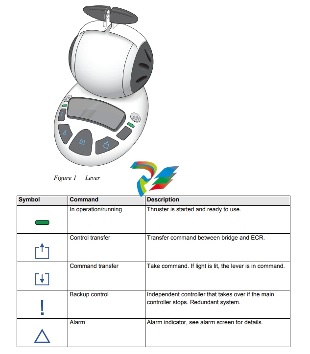
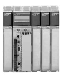
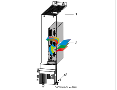
Fig. 1-1: Basic design of a Rexroth IndraDrive controller
The drive controller consists of two essential parts:
● Power section
● Control section
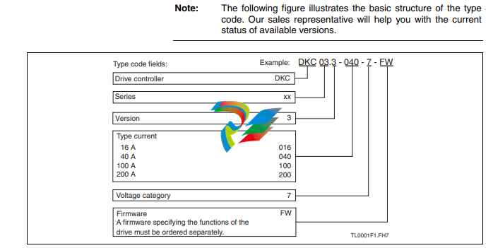
1.2.2 Delivery
The control section is a separate component that is plugged into the power
section. As a standard, the drive controller is supplied ex works as a com‐
plete device including the control section.
Control sections and power sections can also be ordered separately. The re‐
spective firmware package has to be simultaneously ordered for control sec‐
tions.
1.2.3 Mounting and Dismounting the Control Section
General Information
In case the control section is delivered separately, observe the following in‐
structions:
Training
Risk of damage to the control section by im‐
proper handling!
NOTICE
Only such persons trained by Rexroth for mounting and dismounting control
sections are allowed to mount and dismount control sections.
ESD Protection
Risk of damage to the control section and in‐
terference with its operational safety caused
by electrostatic charges!
NOTICE
Exposed conductive parts coming into contact with the control section must
be previously discharged by means of grounding.
Such exposed conductive parts include:
● The human body (ground connection by touching a conductive, groun‐
ded object)
● Parts and tools (place them on a conductive support)
Control sections may only be stored or dispatched in conductive packaging.
Limited Number of Plug-In Actions
Risk of damage to the control section or pow‐
er section by mounting and dismounting the
control section too often!
NOTICE
For a drive controller, the control section must not be mounted and dismoun‐
ted more than a maximum of 20 times.
12/143 Bosch Rexroth AG DOK-INDRV*-CXX02******-PR03-EN-P
IndraDrive Control Sections CSB02, CSE02, CSH02, CDB02
In
Important directions for use
2.1 Appropriate use
2.1.1 Introduction
Rexroth products reflect the state-of-the-art in their development and their
manufacture. They are tested prior to delivery to ensure operating safety and
reliability.
Personal injury and property damage caused
by incorrect use of the products!
WARNING
The products have been designed for use in industrial environments and may
only be used in the appropriate way. If they are not used in the appropriate
way, situations resulting in property damage and personal injury can occur.
Rexroth as manufacturer is not liable for any damages resulting
from inappropriate use. In such cases, the guarantee and the
right to payment of damages resulting from inappropriate use are
forfeited. The user alone carries all responsibility of the risks.
Before using Rexroth products, the following pre-requisites must be met to
ensure appropriate use of the products:
● Personnel that in any way, shape or form uses our products must first
read and understand the relevant safety instructions and be familiar with
their appropriate use.
● If the products take the form of hardware, then they must remain in their
original state, in other words, no structural changes are permitted. It is
not permitted to decompile software products or alter source codes.
● Damaged or faulty products may not be installed or put into operation.
● Make sure that the products have been installed in the manner descri‐
bed in the relevant documentation.
2.1.2 Areas of use and application
Drive controllers made by Rexroth are designed to control electrical motors
and monitor their operation.
Control and monitoring of the Drive controllers may require additional sensors
and actors.
The drive controllers may only be used with the accessories and
parts specified in this documentation. If a component has not
been specifically named, then it may neither be mounted nor con‐
nected. The same applies to cables and lines.
Operation is only permitted in the specified configurations and
combinations of components using the software and firmware as
specified in the relevant Functional Descriptions.
Drive controllers have to be programmed before commissioning to ensure
that the motor executes the specific functions of an application.
Drive controllers of the Rexroth IndraDrive line have been developed for use
in single- and multi-axis drive and control tasks.
To ensure application-specific use of Drive controllers, device types of differ‐
ent drive power and different interfaces are available.
Typical applications include, for example:
● Handling and mounting systems,
● Packaging and food machines,
● Printing and paper processing machines and
● Machine tools.
Drive controllers may only be operated under the assembly and installation
conditions described in this documentation, in the specified position of normal
use and under the ambient conditions as described (temperature, degree of
protection, humidity, EMC, etc.).
2.2 Inappropriate use
Using the Drive controllers outside of the operating conditions described in
this documentation and outside of the technical data and specifications given
is defined as “inappropriate use”.
Drive controllers may not be used, if …
● they are subject to operating conditions that do not meet the specified
ambient conditions. This includes, for example, operation under water,
under extreme temperature fluctuations or extremely high maximum
temperatures.
● Furthermore, Drive controllers may not be used in applications which
have not been expressly authorized by Rexroth. Please carefully follow
the specifications outlined in the general Safety Instructions!
Components of the Rexroth IndraDrive system are products of
category C3 (with limited availability) according to IEC 61800‑3.
To ensure that this category (limit values) is maintained, suitable
line filters must be used in the drive system.
These components are not provided for use in a public low-volt‐
age network supplying residential areas with power. If these com‐
ponents are used in such a public network, high-frequency inter‐
ference is to be expected. This can require additional measures
of radio interference suppression.
Safety instructions for electric drives and controls
3.1 Definitions of terms
Application Documentation Application documentation comprises the entire documentation used to in‐
form the user of the product about the use and safety-relevant features for
configuring, integrating, installing, mounting, commissioning, operating, main‐
taining, repairing and decommissioning the product. The following terms are
also used for this kind of documentation: Operating Instructions, Commis‐
sioning Manual, Instruction Manual, Project Planning Manual, Application De‐
scription, etc.
Component A component is a combination of elements with a specified function, which
are part of a piece of equipment, device or system. Components of the elec‐
tric drive and control system are, for example, supply units, drive controllers,
mains choke, mains filter, motors, cables, etc.
Control system A control system comprises several interconnected control components
placed on the market as a single functional unit.
Device A device is a finished product with a defined function, intended for users and
placed on the market as an individual piece of merchandise.
Electrical equipment Electrical equipment encompasses all devices used to generate, convert,
transmit, distribute or apply electrical energy, such as electric motors, trans‐
formers, switching devices, cables, lines, power-consuming devices, circuit
board assemblies, plug-in units, control cabinets, etc.
Electric drive system An electric drive system comprises all components from mains supply to mo‐
tor shaft; this includes, for example, electric motor(s), motor encoder(s), sup‐
ply units and drive controllers, as well as auxiliary and additional compo‐
nents, such as mains filter, mains choke and the corresponding lines and ca‐
bles.
Installation An installation consists of several devices or systems interconnected for a
defined purpose and on a defined site which, however, are not intended to be
placed on the market as a single functional unit.
Machine A machine is the entirety of interconnected parts or units at least one of
which is movable. Thus, a machine consists of the appropriate machine drive
elements, as well as control and power circuits, which have been assembled
for a specific application. A machine is, for example, intended for processing,
treatment, movement or packaging of a material. The term “machine” also
covers a combination of machines which are arranged and controlled in such
a way that they function as a unified whole.
Manufacturer The manufacturer is an individual or legal entity bearing responsibility for the
design and manufacture of a product which is placed on the market in the in‐
dividual’s or legal entity’s name. The manufacturer can use finished products,
finished parts or finished elements, or contract out work to subcontractors.
However, the manufacturer must always have overall control and possess
the required authority to take responsibility for the product.
Product Examples of a product: Device, component, part, system, software, firmware,
among other things.
Project planning manual A project planning manual is part of the application documentation used to
support the sizing and planning of systems, machines or installations.
Qualified persons In terms of this application documentation, qualified persons are those per‐
sons who are familiar with the installation, mounting, commissioning and op‐
eration of the components of the electric drive and control system, as well as
with the hazards this implies, and who possess the qualifications their work
requires. To comply with these qualifications, it is necessary, among other
things,
● to be trained, instructed or authorized to switch electric circuits and devi‐
ces safely on and off, to ground them and to mark them.
● to be trained or instructed to maintain and use adequate safety equip‐
ment.
● to attend a course of instruction in first aid.
User A user is a person installing, commissioning or using a product which has
been placed on the market.
3.2 General information
3.2.1 Using the Safety instructions and passing them on to others
Do not attempt to install and operate the components of the electric drive and
control system without first reading all documentation provided with the prod‐
uct. Read and understand these safety instructions and all user documenta‐
tion prior to working with these components. If you do not have the user doc‐
umentation for the components, contact your responsible Rexroth sales part‐
ner. Ask for these documents to be sent immediately to the person or per‐
sons responsible for the safe operation of the components.
If the component is resold, rented and/or passed on to others in any other
form, these safety instructions must be delivered with the component in the
official language of the user’s country.
Improper use of these components, failure to follow the safety instructions in
this document or tampering with the product, including disabling of safety de‐
vices, could result in property damage, injury, electric shock or even death.
3.2.2 Requirements for safe use
Read the following instructions before initial commissioning of the compo‐
nents of the electric drive and control system in order to eliminate the risk of
injury and/or property damage. You must follow these safety instructions.
● Rexroth is not liable for damages resulting from failure to observe the
safety instructions.
● Read the operating, maintenance and safety instructions in your lan‐
guage before commissioning. If you find that you cannot completely un‐
derstand the application documentation in the available language,
please ask your supplier to clarify.
● Proper and correct transport, storage, mounting and installation, as well
as care in operation and maintenance, are prerequisites for optimal and
safe operation of the component.
● Only qualified persons may work with components of the electric drive
and control system or within its proximity.
● Only use accessories and spare parts approved by Rexroth.
● Follow the safety regulations and requirements of the country in which
the components of the electric drive and control system are operated.
● Only use the components of the electric drive and control system in the
manner that is defined as appropriate. See chapter “Appropriate Use”.
● The ambient and operating conditions given in the available application
documentation must be observed.
16/143 Bosch Rexroth AG DOK-INDRV*-CXX02******-PR03-EN-P
IndraDrive Control Sections CSB02, CSE02, CSH02, CDB02
S
Safety instructions for electric drives and controls
Applications for functional safety are only allowed if clearly and explicitly
specified in the application documentation “Integrated Safety Technolo‐
gy”. If this is not the case, they are excluded. Functional safety is a safe‐
ty concept in which measures of risk reduction for personal safety de‐
pend on electrical, electronic or programmable control systems.
● The information given in the application documentation with regard to
the use of the delivered components contains only examples of applica‐
tions and suggestions.
The machine and installation manufacturers must
– make sure that the delivered components are suited for their indi‐
vidual application and check the information given in this applica‐
tion documentation with regard to the use of the components,
– make sure that their individual application complies with the appli‐
cable safety regulations and standards and carry out the required
measures, modifications and complements.
● Commissioning of the delivered components is only allowed once it is
sure that the machine or installation in which the components are instal‐
led complies with the national regulations, safety specifications and
standards of the application.
● Operation is only allowed if the national EMC regulations for the applica‐
tion are met.
● The instructions for installation in accordance with EMC requirements
can be found in the section on EMC in the respective application docu‐
mentation.
The machine or installation manufacturer is responsible for compliance
with the limit values as prescribed in the national regulations.
● The technical data, connection and installation conditions of the compo‐
nents are specified in the respective application documentations and
must be followed at all times.
National regulations which the user has to comply with
● European countries: In accordance with European EN standards
● United States of America (USA):
– National Electrical Code (NEC)
– National Electrical Manufacturers Association (NEMA), as well as
local engineering regulations
– Regulations of the National Fire Protection Association (NFPA)
● Canada: Canadian Standards Association (CSA)
● Other countries:
– International Organization for Standardization (ISO)
– International Electrotechnical Commission (IEC)
3.2.3 Hazards by improper use
● High electrical voltage and high working current! Danger to life or seri‐
ous injury by electric shock!
● High electrical voltage by incorrect connection! Danger to life or injury by
electric shock!
● Dangerous movements! Danger to life, serious injury or property dam‐
age by unintended motor movements!
● Health hazard for persons with heart pacemakers, metal implants and
hearing aids in proximity to electric drive systems!
● Risk of burns by hot housing surfaces!
● Risk of injury by improper handling! Injury by crushing, shearing, cutting,
hitting!
● Risk of injury by improper handling of batteries!
● Risk of injury by improper handling of pressurized lines!
3.3 Instructions with regard to specific dangers
3.3.1 Protection against contact with electrical parts and housings
This section concerns components of the electric drive and con‐
trol system with voltages of more than 50 volts.
Contact with parts conducting voltages above 50 volts can cause personal
danger and electric shock. When operating components of the electric drive
and control system, it is unavoidable that some parts of these components
conduct dangerous voltage.
High electrical voltage! Danger to life, risk of injury by electric shock or seri‐
ous injury!
● Only qualified persons are allowed to operate, maintain and/or repair the
components of the electric drive and control system.
● Follow the general installation and safety regulations when working on
power installations.
● Before switching on, the equipment grounding conductor must have
been permanently connected to all electric components in accordance
with the connection diagram.
● Even for brief measurements or tests, operation is only allowed if the
equipment grounding conductor has been permanently connected to the
points of the components provided for this purpose.
● Before accessing electrical parts with voltage potentials higher than
50 V, you must disconnect electric components from the mains or from
the power supply unit. Secure the electric component from reconnec‐
tion.
● With electric components, observe the following aspects:
Always wait 30 minutes after switching off power to allow live capacitors
to discharge before accessing an electric component. Measure the elec‐
trical voltage of live parts before beginning to work to make sure that the
equipment is safe to touch.
● Install the covers and guards provided for this purpose before switching
on.
● Never touch any electrical connection points of the components while
power is turned on.
● Do not remove or plug in connectors when the component has been
powered.
● Under specific conditions, electric drive systems can be operated at
mains protected by residual-current-operated circuit-breakers sensitive
to universal current (RCDs/RCMs).
18/143 Bosch Rexroth AG DOK-INDRV*-CXX02******-PR03-EN-P
IndraDrive Control Sections CSB02, CSE02, CSH02, CDB02
S
● Secure built-in devices from penetrating foreign objects and water, as
well as from direct contact, by providing an external housing, for exam‐
ple a control cabinet.
High housing voltage and high leakage current! Danger to life, risk of injury
by electric shock!
● Before switching on and before commissioning, ground or connect the
components of the electric drive and control system to the equipment
grounding conductor at the grounding points.
● Connect the equipment grounding conductor of the components of the
electric drive and control system permanently to the main power supply
at all times. The leakage current is greater than 3.5 mA.
● Establish an equipment grounding connection with a minimum cross
section according to the table below. With an outer conductor cross sec‐
tion smaller than 10 mm2
(8 AWG), the alternative connection of two
equipment grounding conductors is allowed, each having the same
cross section as the outer conductors.
Cross section outer con‐
ductor
Minimum cross section equipment grounding conductor
Leakage current ≥ 3.5 mA
1 equipment grounding
conductor
2 equipment grounding
conductors
1.5 mm2
(16 AWG)
10 mm2
(8 AWG)
2 × 1.5 mm2
(16 AWG)
2.5 mm2
(14 AWG) 2 × 2.5 mm2
(14 AWG)
4 mm2
(12 AWG) 2 × 4 mm2
(12 AWG)
6 mm2
(10 AWG) 2 × 6 mm2
(10 AWG)
10 mm2
(8 AWG) –
16 mm2
(6 AWG)
16 mm2
(6 AWG)
–
25 mm2
(4 AWG) –
35 mm2
(2 AWG) –
50 mm2
(1/0 AWG) 25 mm2
(4 AWG)
Protective extra-low voltage as protection against electric shock
Protective extra-low voltage is used to allow connecting devices with basic in‐
sulation to extra-low voltage circuits.
On components of an electric drive and control system provided by Rexroth,
all connections and terminals with voltages up to 50 volts are PELV (“Protec‐
tive Extra-Low Voltage”) systems. It is allowed to connect devices equipped
with basic insulation (such as programming devices, PCs, notebooks, display
units) to these connections.
Danger to life, risk of injury by electric shock! High electrical voltage by incor‐
rect connection!
If extra-low voltage circuits of devices containing voltages and circuits of
more than 50 volts (e.g., the mains connection) are connected to Rexroth
products, the connected extra-low voltage circuits must comply with the re‐
quirements for PELV (“Protective Extra-Low Voltage”).
3.3.3 Protection against dangerous movements
Dangerous movements can be caused by faulty control of connected motors.
Some common examples are:
● Improper or wrong wiring or cable connection
● Operator errors
● Wrong input of parameters before commissioning
● Malfunction of sensors and encoders
● Defective components
● Software or firmware errors
These errors can occur immediately after equipment is switched on or even
after an unspecified time of trouble-free operation.
The monitoring functions in the components of the electric drive and control
system will normally be sufficient to avoid malfunction in the connected
drives. Regarding personal safety, especially the danger of injury and/or
property damage, this alone cannot be relied upon to ensure complete safety.
Until the integrated monitoring functions become effective, it must be as‐
sumed in any case that faulty drive movements will occur. The extent of faulty
drive movements depends upon the type of control and the state of opera‐
tion.
Dangerous movements! Danger to life, risk of injury, serious injury or property
damage!
A risk assessment must be prepared for the installation or machine, with its
specific conditions, in which the components of the electric drive and control
system are installed.
As a result of the risk assessment, the user must provide for monitoring func‐
tions and higher-level measures on the installation side for personal safety.
The safety regulations applicable to the installation or machine must be taken
into consideration. Unintended machine movements or other malfunctions
are possible if safety devices are disabled, bypassed or not activated.
To avoid accidents, injury and/or property damage:
● Keep free and clear of the machine’s range of motion and moving ma‐
chine parts. Prevent personnel from accidentally entering the machine’s
range of motion by using, for example:
– Safety fences
– Safety guards
– Protective coverings
– Light barriers
● Make sure the safety fences and protective coverings are strong enough
to resist maximum possible kinetic energy.
● Mount emergency stopping switches in the immediate reach of the oper‐
ator. Before commissioning, verify that the emergency stopping equip‐
ment works. Do not operate the machine if the emergency stopping
switch is not working.
● Prevent unintended start-up. Isolate the drive power connection by
means of OFF switches/OFF buttons or use a safe starting lockout.
● Make sure that the drives are brought to safe standstill before accessing
or entering the danger zone.
● Additionally secure vertical axes against falling or dropping after switch‐
ing off the motor power by, for example,
– mechanically securing the vertical axes,
– adding an external braking/arrester/clamping mechanism or
– ensuring sufficient counterbalancing of the vertical axes.
● The standard equipment motor holding brake or an external holding
brake controlled by the drive controller is not sufficient to guarantee per‐
sonal safety!
● Disconnect electrical power to the components of the electric drive and
control system using the master switch and secure them from reconnec‐
tion (“lock out”) for:
– Maintenance and repair work
– Cleaning of equipment
– Long periods of discontinued equipment use
● Prevent the operation of high-frequency, remote control and radio equip‐
ment near components of the electric drive and control system and their
supply leads. If the use of these devices cannot be avoided, check the
machine or installation, at initial commissioning of the electric drive and
control system, for possible malfunctions when operating such high-fre‐
quency, remote control and radio equipment in its possible positions of
normal use. It might possibly be necessary to perform a special electro‐
magnetic compatibility (EMC) test.
3.3.4 Protection against electromagnetic and magnetic fields during opera‐
tion and mounting
Electromagnetic and magnetic fields!
Hazards for persons with active medical implants or passive metallic im‐
plants, as well as for pregnant women.
● Persons with active medical implants (e.g. heart pacemakers), passive
metallic implants (e.g. hip implants) and pregnant women might possibly
risk hazards by electromagnetic or magnetic fields in the immediate vi‐
cinity of components of the electric drive and control system and the as‐
sociated current-carrying conductors.
Entering the following areas can cause danger to these persons:
– Areas in which components of the electric drive and control system
and the associated current-carrying conductors are mounted, com‐
missioned and operated.
– Areas in which parts of motors with permanent magnets are stored,
repaired or mounted.
● Before entering these areas, the above-mentioned persons should seek
advice from their physician.
● Observe the occupational safety and health regulations applicable at the
site of operation, for installations equipped with components of the elec‐
DOK-INDRV*-CXX02******-PR03-EN-P Bosch Rexroth AG 21/143
IndraDrive Control Sections CSB02, CSE02, CSH02, CDB02
S
Protection against contact with hot parts
Hot surfaces of components of the electric drive and control system. Risk of
burns!
● Do not touch hot surfaces of, for example, braking resistors, heat sinks,
supply units and drive controllers, motors, windings and laminated
cores!
● According to the operating conditions, temperatures of the surfaces can
be higher than 60 °C (140 °F) during or after operation.
● Before touching motors after having switched them off, let them cool
down for a sufficient period of time. Cooling down can require up to 140
minutes! The time required for cooling down is approximately five times
the thermal time constant specified in the technical data.
● After switching chokes, supply units and drive controllers off, wait 15 mi‐
nutes to allow them to cool down before touching them.
● Wear safety gloves or do not work at hot surfaces.
● For certain applications, and in accordance with the respective safety
regulations, the manufacturer of the machine or installation must take
measures to avoid injuries caused by burns in the final application.
These measures can be, for example: Warnings at the machine or in‐
stallation, guards (shieldings or barriers) or safety instructions in the ap‐
plication documentation.
3.3.6 Protection during handling and mounting
Risk of injury by improper handling! Injury by crushing, shearing, cutting, hit‐
ting!
● Observe the relevant statutory regulations of accident prevention.
● Use suitable equipment for mounting and transport.
● Avoid jamming and crushing by appropriate measures.
● Always use suitable tools. Use special tools if specified.
● Use lifting equipment and tools in the correct manner.
● Use suitable protective equipment (hard hat, safety goggles, safety
shoes, safety gloves, for example).
● Do not stand under hanging loads.
● Immediately clean up any spilled liquids from the floor due to the risk of
falling!
3.3.7 Battery safety
Batteries consist of active chemicals in a solid housing. Therefore, improper
handling can cause injury or property damage.
Risk of injury by improper handling!
● Do not attempt to reactivate low batteries by heating or other methods
(risk of explosion and cauterization).
● Do not attempt to recharge the batteries as this may cause leakage or
explosion.
● Do not throw batteries into open flames.
● Do not dismantle batteries.
● When replacing the battery/batteries, do not damage the electrical parts
installed in the devices.
● Only use the battery types specified for the product.
Environmental protection and disposal! The batteries contained in
the product are considered dangerous goods during land, air, and
sea transport (risk of explosion) in the sense of the legal regula‐
tions. Dispose of used batteries separately from other waste. Ob‐
serve the national regulations of your country.
3.3.8 Protection against pressurized systems
According to the information given in the Project Planning Manuals, motors
and components cooled with liquids and compressed air can be partially sup‐
plied with externally fed, pressurized media, such as compressed air, hy‐
draulics oil, cooling liquids and cooling lubricants. Improper handling of the
connected supply systems, supply lines or connections can cause injuries or
property damage.
Risk of injury by improper handling of pressurized lines!
● Do not attempt to disconnect, open or cut pressurized lines (risk of ex‐
plosion).
● Observe the respective manufacturer’s operating instructions.
● Before dismounting lines, relieve pressure and empty medium.
● Use suitable protective equipment (safety goggles, safety shoes, safety
gloves, for example).
● Immediately clean up any spilled liquids from the floor due to the risk of
falling!
Environmental protection and disposal! The agents (e.g., fluids)
used to operate the product might not be environmentally friendly.
Dispose of agents harmful to the environment separately from
other waste. Observe the national regulations of your country.
DOK-INDRV*-CXX02******-PR03-EN-P Bosch Rexroth AG 23/143
IndraDrive Control Sections CSB02, CSE02, CSH02, CDB02
S
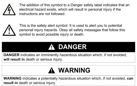
Explanation of signal words and the Safety alert symbol
The Safety Instructions in the available application documentation contain
specific signal words (DANGER, WARNING, CAUTION or NOTICE) and,
where required, a safety alert symbol (in accordance with
ANSI Z535.6-2011).
The signal word is meant to draw the reader’s attention to the safety instruc‐
tion and identifies the hazard severity.
The safety alert symbol (a triangle with an exclamation point), which pre‐
cedes the signal words DANGER, WARNING and CAUTION, is used to alert
the reader to personal injury hazards.
DANGER
In case of non-compliance with this safety instruction, death or serious injury
will occur.
WARNING
In case of non-compliance with this safety instruction, death or serious injury
could occur.
CAUTION
In case of non-compliance with this safety instruction, minor or moderate in‐
jury could occur.
NOTICE
In case of non-compliance with this safety instruction, property damage could
occur.