This guide describes the PC-E984-381 and PC-E984-385/385D Programmable
Logic Controller systems together with system planning information and installation procedures.
For brevity and your convenience, the PC-E984-381/385 controller is referred to
in context as the Model 381 E or 385E. Both Model 381 E and 385E are enhanced
with an extra Modbus Port.. The 385D is a 125 VDC version which is otherwise
just like a 385E.
In the context of this manual, the terms “Programmable Controller” and “Programmable Logic Controller” have been abbreviated to “PLC” for brevity. References to
IBMs ’ personal computer are written out or in context with IBMs ’ initials.
It is necessary to say that the information in this document is subject to change
without notice and should not be construed as a commitment by MODICON, Inc.,
Industrial Automation Systems. MODICON, Inc. assumes no responsibility for any
errors that may appear in this document. Further, no part of this document may be
reproduced in any form or by any means, electronic or mechanical, without the express written permission of MODICON, Inc., Industrial Automation Systems. All
IBM8 is a registered trademark of International Business Machines, Inc.; IBM PC
is a trademark of International Business Machines, Inc.
0 Copyright 1992 Modicon, Inc.
This manual has been written to help you plan, configure, mount, wire, connect,
check out and, if necessary, troubleshoot your PC-E984_381/385/385D PC system. After reading this publication:
A Control Engineer will be able to identify and physically plan the location and
mounting of system components.
A Plant Electrician/Installer will be able to install, power-up and check out the
system.
A Maintenance Technician will be able to recognize, locate, identify and resolve
or report system failures.
How To Use This Manual
Chapter 1 describes the E984-38x model PC systems ’ functions.
Chapter 2 offers information for planning your installation with Local I/O.
Chapter 3 is an installation procedure for your controller with local I/O.
Appendix A gives system specifications including a summary table of l/O module
specifications.
Appendix B gives Stopped Error Codes, MODBUS cable connector pinouts, a
table of MODICON 381 E/385E/385D system end-user part numbers, Customer
Service/Technical Support telephone numbers, and Installation Verification troubleshooting charts.
GM-MSFT-001
GM-0984-SYS
Modsoft Programmer User Guide
984 Programmable Controller Systems
Manual
Incoming Inspection Guidelines
Procedure Guidelines for inspection
Step 1 Before you do anything, verify your shipment is complete and undamaged. If the shipment is incomplete or
damaged, notify the carrier and your distributor.
Step 2 Remove everything from its packing and check for
physical defects or damage. If the equipment is physically
defective or damaged, notify your MODICON representative.
li7 Note Save shipping materials until installation is complete.
Sending Something Back?
o To the extent possible, use the original packing materials supplied by
MODICON.
o All equipment should be firmly packed so that it cannot move around in its shipping container.
o All equipment should be protected against impact during shipment.
Overview
The Modicon 984 Model 381 E, 385E and 385D Controller is a mid-range Programmable Logic Controller in a modular, expandable, architecture. It employs
Modicon 800 series housings, interfaces and I/O modules. The Model “E” is supported by the same instruction set as the other 984 Controller models and is programmed by the Modicon Modsoft Programming Panel.
IF Note The 385D Model is the same as the 385E except it is the
125VDC version.
Figure 1 is a perspective view of the 381 E/385E and 385D systems ’ controller
module with built-in power supply. Certain physical features are noted.
System Features
The Model 381 E/385E/385D systems ’ features are described below followed by
somewhat more detailed functional descriptions.
System Capacity
The Model 381 E/385E memory provisions are summarized in Table 1:
The user logic and state RAM support one local drop. This local drop has a maximum I/O module capacity of 21 I/O Modules (19 modules if an auxiliary power
supply is required) and up to 512 discrete points of local I/O (any mix).
Executive NV RAM
The Model “E” controller has its ’ bootable memory and executive software downloaded to Non Volatile RAM during the manufacturing process and is not accessible to the user.
Executive Functionalitv
381 E
Executive ID of 813 (Hex), CPU Clock speed 12 Mhz.
(MSTR is the user interface to Modbus Plus. It replaces the CKSM function
and uses its opcode.
One Modbus port, One Modbus Plus Port, Time-of-Day clock, Peer Cop,
Local I/O only.
Module Housings
The Model 381 E/385E system uses Modicon 800 series housings for its controller
and I/O modules; specifically, a 19” primary housing with a seven module capacity
or a 27” primary housing with an eleven module capacity.
Primary Enclosure – With the single width Model “E” controller in your primary enclosure, the 19’ and 27” primary enclosures will accommodate up to 6 or IO I/O
modules, respectively.
Secondary Enclosure -The secondary housing will accommodate a one and onehalf wide P810, P800 or P884 auxiliary power supply if a power supply expander
is required and as many I/O modules as there is room remaining.
Specifically, the standard 19” or 27” secondary housings will accommodate five or
nine I/O modules along with a one and one-half wide (two-slot) auxiliary power
supply and a full seven or eleven I/O modules without the power supply.
The 1 g-inch primary housing with controller is shown in Figure 2. For simplicitys ’
sake, the 27” housing is not shown in this manual except as required in the illustration on panel mounting dimensions.
Construction
The Model “E” controller is housed in a rugged metal chassis designed to withstand specified temperature and humidity extremes as well as vibration, shock,
and ambient atmospheric conditions consistent with the “factory floor.”
The primary housing employs a shielded backplane which provides for internal
communications within the housing. The backplane protects the internal system
communications from both electromagnetic (EMI) and radio frequency interference
(RFI).
Captive screws secure all modules in the housings and they should be used to insure good electrical contact between the connector at the rear of the module and
backplane in the housing. Key pin protection is also available.
User memory is backed up by a lithium battery which has a one year service life.
It will hold-up for 14 days after the BAT LOW indicator comes on. The batterys ’
installed but unused service life is rated at one year, with a five year shelf life.
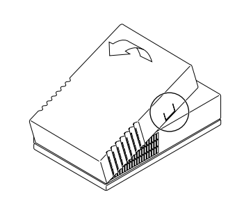
A manually operated memory-protect toggle switch prevents accidental access to
the users ’ program. This switch is located on the left side of the unit, above the 3
position communications toggle switch (see Figure 3).
Power Supply Function (AC and DC)
The Model 381 E/385E and 385D systems ’ controller module comes with a built-in
I/O power supply.
The Model “E” Controllers run on 97 through 276 VAC (47 to 63 Hertz) and 24Vdc.
As shown on Figure 3, Once connected, AC power is then switched ON/OFF with
a front panel rocker switch.
The PLC will also operate continuously on 24Vdc as its an alternate or exclusive
source. Figure 3 shows a primary power input connector for a customer supplied
24Vdc source. Once connected, DC power is then switched ON/OFF with a front
panel rocker switch.
Figure 3 Wiring Connectors, Communications and Memory Switches
The 385D input can range from 105 to 150 VDC with the nominal at 125 VDC controlled by a front panel rocker switch. The 24 VDC option is also available.
Note The primary power DC input feature was not designed, nor is it
suitable as an automatic battery backup provision in the event of an AC
outage. This is because the controllers ’ externally sourced DC input
joins with the AC.sourced, internally produced DC. At any given time,
the Controller is taking from the higher of the two DC voltage sources if
there is as little as a 1 V differential. The consequence of this would be
to draw down the DC battery if there were an extended period(s) of reduced AC voltage supply.
8 Controller Introduction
If you want a backup alternative, one could be configured from a user-supplied
DC power supply with its own backup batten and charger combination along with
appropriate monitoring provisions.
Communications Processing Function
The Models 381 E/385E/385D have Modbus capability for data transfer and remote
programming. Through this port, communication processing on the CPU board
can be linked from the controller to supervisory and programming devices such as
a host computer or Modicon programmer. The Modbus port allows you to schedule one Modbus service per scan. The Model 381 has a second Modbus port
which allows you to incorporate your controller into the Modbus network and still
have a free port for connecting your local programming panel The second port on
the 385E and D is for the Modbus Plus network Connection..
Figure 3 illustrated the controller from the left side. The MEM/DEFAULT/MODEM
toggle switch enables your preset communications configuration for Modbus port
1. (For software configuration, refer to software configurator in Panel software
documentation.)
The DIP switch for setting Modbus Plus port parameters is shown at the bottom of
the illustration but access to the DIP switch is actually through the bottom of the
modules ’ case.
Central Processing Unit (CPU) Function
The Model “E” uses 24 bit memory architecture and a 16 bit CPU which is fully
compatible with the Modicon 984 PC instruction set, solves user logic at a nominal
rate of 2.5 ms per thousand nodes of user logic. For special applications, a timeof-day clock is provided on all “E” Models.
Mainframe Status Indicators
Status indicators on the CPU module are:
POWER OK
READY
RUN
BATTERY LOW
MODBUS Port 1
MODBUS Port 2
Green LED: When ON, indicates input power OK and voltage outputs OK. Your l/O power OK is indicated by the
READY LED.
Amber LED: When ON, indicates Controller passed powerup diagnostics. Remains ON in Stopped and Run modes
as long as health status is OK. Indicator is OFF when an
error condition is detected by diagnostics.
Green LED: When ON, indicates Controller is in the RUN
mode and solving logic. If memory checksum fails this light
will blink 3 times for 5 seconds followed by a rest period of
2.5 seconds then the pattern repeats. The controller is in
Kernal mode and needs the executive reloaded.
Red LED: When ON, indicates battery needs to be replaced (14 day holdup from initial indication).
Green LED: When ON, indicates communication processor
has unit address and communications are in progress.
Green LED: When ON, indicates communication processor
has unit address and communications are in progress.
(The port 2 indicator is labeled MODBUS PLUS on the 385E and 385D and
indicates status as:)
MODBUS PLUS Green LED This LED displays a flashing repetitive pattern to indicate the node status:
NORMAL flashes every 160 msec.
MONITOR NETWORK flashes at one
second intervals. Is in offline state receive only.
NOT RECEIVING TOKEN flashes two times then is off for
two seconds.
SOLE STATION flashes three times then is off for 1.7 seconds.
DUPLICATE NODE ADDRESS flashes four times then is
off for 1.4 seconds.
Overview
The 381 E/385E and 385D Controller is designed to work with your Modicon Modsoft programming panel; Modicon 800 series housings, interfaces and I/O modules.
The site planner must also consider the peripheral equipment (such as a Programming panel, CRT monitor, or printer) when preparing an installation plan for
the site. Refer to the appropriate Modicon publications for site preparation procedures for related equipment.
Space Requirements
For the primary module housing, allow 12 inch clearance to the left so installer can
see power supply connectors. Allow 6 inches on the top and side of the housing
for convection cooling in vertical mounting situations. Allow 12 inch of clearance
at the bottom of the Controller for cable access.
For all other housings, allow 6 inches on the top and sides of each housing for unobstructed cooling airflow in vertical mounting situations.
Also consider installation and physical access for removal of the modules as well
as subsequent service including the connection and detachment of signal and
power cables when required.
The primary housing may be separated up to 12 feet from the secondary housing
depending only on the on the cable length employed.
Primary Power Lines
In addition to service access, distance to power sources has to be considered in
planning your controller installation. In addition to cable routing considerations,
good practices dictate that the power lines be dedicated to the PC installation to
minimize problems that sometimes arise when sharing AC power with electrically
noisy equipment.
Finally, plan to install a service loop and a cable restraint as the primary power
cable as the connector is not locked in place.
Environmental Requirements
In planning for controller installation, consideration should be given to the environment around the controller. Although designed for a harsh industrial environment
and able to withstand factors that would harm other types of electronic equipment,
problems can be avoided by not placing the controller and its related equipment in
an operating area where there is high ambient temperature, acidic atmosphere, vibration, dust, and dirt if it can be avoided.
Mounting Hardware Requirements
After deciding on the final location of the Controller, its associated equipment and
cables, you should plan for related mounting hardware. This would include such
items as: nut and bolt combinations, flat and star washers, housings, mounting
surface, ground straps and system ground connections.
Mounting bolts are NOT provided. The recommended mounting bolts are
0.312-24 UNF-2B (insert or tapped) stainless steel (#8-l 3-SS).
he 984-381 El385E and 385D system housing can be panel/bulkhead mounted
or rack mounted as described in the following text.
Panel or Bulkhead Mounting
As shown in Figure 4 below, the H819 housing has keyholes at the top and bottom
of the housing for bulkhead mounting purposes. The keyholes are sized for
5/16-inch bolts. The recommended ground point is also shown.
Read and observe this manual before you work on the PacDrive Controller for the first
time. Take particular note of the safety instructions. As described in section 2.2, only
those persons who meet the “Selection and qualification of employees” are allowed to
work on the PacDrive Controller.
A copy of this manual must always be available for personnel who are entrusted to
work on the PacDrive Controller.
This manual is intended to help you use the PacDrive Controller and its intended ap‐
plications safely and properly.
By observing this manual, you will help to
• avoid risks,
• reduce repair costs and down times of the PacDrive Controller,
• increase the life span of the PacDrive Controller
• and increase reliability of the PacDrive Controller.
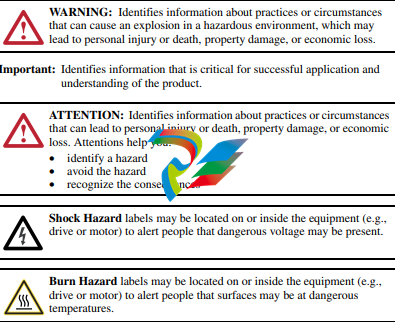
Symbols, designator and display format of safety notes
This manual divides the safety instructions into four various categories.
Hazards and possible results will be categorized using a certain combination of sym‐
bols and signal words.
Notes for working safely with the product
The PacDrive Controller is state of the art and conform to recognized technical safety
regulations. Nevertheless the use of the PacDrive Controller can present a hazard to
life and limb or cause property damage. The following section contains general re‐
quirements for safe work with the PacDrive Controller. Each person who uses or works
on the PacDrive Controller must read and follow these requirements.
2.1 Proper use
Use The PacDrive Controller is intended to be installed in a machine or assembled with
other components to form a machine or system.
What do you
need to ob‐
serve?
Proper use includes that you observe the following points and the resulting rules:
• The regulative, warning and instruction signs on the connected components and
in the switching cabinet
• The warning instructions on the PacDrive Controller on the connected components
and in the switch cabinet
• The inspection and maintenance instructions
• The operating instructions of the other components
• All other documentation
Flawless
State
Operate the PacDrive Controller only when they are in a flawless technical condition.
Observe the regulations, act with safety and hazards in mind If circumstances occur
that impact safety or cause changes in the operating performance of the PacDrive
Controller, switch the PacDrive Controller off immediately and contact the responsible
service staff.
Only original
equipment
must be used
Use only the options and mounting parts specified in the documentation and no thirdparty devices or components that are not expressly approved ELAU recommends. Do
not change the PacDrive Controller inappropriately.
Protection
measures
provide for
Before installing, provide for appropriate protective devices in compliance with the local
and national standards. Do not commission components without accordant protective
devices. After installation, commissioning or repair, test the protective devices used.
Forbidden
environments
The components must not be used in the following environments:
• In dangerous (explosive) atmospheres
• In mobile, movable or floating systems
• In life support systems
• In domestic appliances
Installation
and operating
ambient
You may only use them in accordance with the installation and operating conditions
described in the documentation. The operating conditions at the installation location
must be checked and maintained in accordance with the required technical data (per‐
formance data and ambient conditions). Commissioning is prohibited until it is guar‐
anteed that the usable machine or system in which the PacDrive Controller is installed
meets all requirements of EC Directive 98/37/EC (machinery directive).
In addition, the following standards, directives and regulations are to be observed:
• DIN EN 60204 Safety of machinery: Electrical equipment of machines
• DIN EN 292 Part 1 and Part 2 Safety of machinery: Basic Concepts, General Prin‐
ciples for Design
• DIN EN 50178 Electronic equipment for use in high-current electrical systems
• EMC directive 2004/108/EG
• The generally applicable local and national safety and accident prevention regu‐
lations.
• The rules and regulations on accident prevention and environmental protection that
apply in the country where the product is used
• The applicable laws and ordinances
2.2 Selection and qualification of personnel
Target Audi‐
ence
of this manual
This manual is geared exclusively toward technically qualified personnel, who have
detailed knowledge in the field of automation technology. The description is mainly for
construction and application engineers from the engineering and electro-technics di‐
vision as well as service and commissioning engineers.
Specialist or
trained
staff
Work on the PacDrive Controller may only be carried out by qualified professional or
by trained staff under the instruction and supervision of a qualified person in accord‐
ance with electrical regulations. Professionals are those persons who, as a result of
their training, knowledge, and experience and knowledge of the pertinent regulations,
can
• evaluate the transferred work,
• recognize the meaning of the safety instructions and implement them consistently,
• recognize possible hazards and
• take appropriate safety measures
Rest dangers
Health risks arising from the PacDrive Controller have been reduced by means of
safety technology and design engineering. However a residual risk remains, since the
PacDrive Controller works with electrical voltage and electrical currents.
If activities involve residual risks, a warning instruction is made at the appropriate
points. The note details the potential hazard and its effects and describes preventative
measures to avoid it.
Mounting and handling
Touching electrical parts
DANGER
ELECTRIC SHOCK, FIRE OR EXPLOSION CAUSED BY HIGH VOLTAGE
• Observe the general construction and safety regulations for working on highcurrent electrical systems.
• After installation, check the firm connection of the ground conductor to all elec‐
trical units to ensure that connection complies with the connection diagram.
• Always make sure that the ground conductor is connected when operating elec‐
trical components.
• Before working on electrical equipment with a voltage greater than 50 volts, the
main switch has to be in the “OFF” position and secured, so it cannot be restarted.
• Disconnect devices with a voltage greater than 30 V rms or 42,2 V DC from the
power supply before working on electrical parts.
• Wait at least 5 minutes after switching off before accessing the components.
• Before working on the equipment, discharge the DC bus and use a voltage meter
to make sure that there is no voltage.
• Do not touch the electrical connection points of the components when the device
is switched on.
• Make sure that the drives are at a standstill because potentially fatal voltage can
occur on the motor lines in generator operation.
• Before enabling the device, safely cover the live components to prevent contact.
• Disconnect power connector cables only when the system is deactivated.
• Plug in power connector cables only when the system is deactivated.
• Provide for protection against indirect contact (DIN EN 50178, Section 5.3.2).
• If you are not using prefabricated ELAU cables, check that the assignment of the
new cables complies with the connection diagram of the machine manufacturer.
Failure to follow these instructions will result in death or serious injury.
Dangerous movements
There can be different causes of dangerous movements:
• Missing or faulty homing of the robot mechanics
• Wiring or cabling errors
• Errors in the application program
• Component errors
• Error in the measured value and signal transmitter
• Operation error
Personal safety must be guaranteed by primary equipment monitoring or measures.
Don’t just rely on the internal monitoring of the drive components. Monitoring or meas‐
ures should be implemented based on the specific characteristics of the equipment,
in line with a risk and error analysis. This includes the valid safety regulations for the
equipment.
DANGER
DANGEROUS MOVEMENTS
• Prevent entry to a danger zone, e.g. by means protective fencing, mesh guards,
protective covers, or light barriers.
• Ensure the protective devices are properly dimensioned.
• Under no circumstances must the technical safety devices be removed.
• Do not make any modifications to a protective device that may put it out of op‐
eration.
• Protect existing work stations against unauthorized operation.
• Effectively restrict access to the control terminals to allow access only to author‐
ized persons.
• Position EMERGENCY OFF switches so that they are easily accessible and can
be reached quickly.
• Check the functionality of EMERGENCY OFF equipment before start-up and
during maintenance periods.
• Prevent unintentional start-ups by disconnecting the drives from power supply
using the EMERGENCY OFF circuit or using a safe start-up lock out.
• Before accessing the drives or entering the danger zone, safely bring the drives
to a stop.
• While working on the system, power down the electrical equipment using the
main switch and prevent it from being switched back on.
• Secure the system from being switched back on before working on it.
• Avoid operating high-frequency, remote control, and radio devices close to the
system electronics and their feed lines.
• Prior to the initial start-up, check the system and the installation for possible mal‐
functions in all usage scenarios.
• If necessary, carry out a special EMC check of the system.
Failure to follow these instructions will result in death or serious injury
Safe separated extra-low voltage”
PELV Protec‐
tive Extra-Low
Voltage
The signal voltage and control voltage of the PacDriveTM devices are <33 Volts. In this
range, the specification as a PELV system in accordance with IEC 60364-4-41 in‐
cludes a protective measure to guard against direct and indirect contact with danger‐
ous voltage through the safe separation of the primary and secondary sides in the
system/machine. ELAU strongly recommends providing the system/machine with safe
isolation.
DANGER
HIGH ELECTRICAL VOLTAGE DUE TO INCORRECT CONNECTION
• Please ensure that only devices, electrical components or lines that have suffi‐
cient, safe electrical separation from the connected circuits in accordance with
the standards (EN 50178 / 1998 edition – Electronic equipment for use in power
stations) are connected to the signal voltage connectors of this component.
• Ensure that the existing electrical separation is maintained throughout the entire
circuit.
Failure to follow these instructions will result in death or serious injury
FELV Function‐
al Extra-Low
Voltage
When using ELAU Components in systems that do not have safe separation as a
protective measure against direct or indirect contact of dangerous voltages, all con‐
nections and contacts (e.g. PacDrive Controller, Sub-D connector, serial interface) that
do not meet protection class IP2X require a permanent cover. The cover or the device
connection of the connected device must be designed so that it can only be removed
by using a tool. The protective measures have to be adhered on all connected devices
Indicators, control elements, diagnosis
The PacDrive™ System supports the user with its comprehensive diagnostic sys‐
tem.
The diagnostic messages can be read out with the Automation Toolkit EPAS-4 . The
PacDrive™ System contains a powerful message logger in which additional diagnostic
information is recorded.
Diagnostic messages are usually displayed by a control panel on the machine. If an
“error” occurs, read the diagnostic message on this unit and then contact the machine
manufacturer.
Detailed information on diagnosis is available in the Online Help of the Automation
Toolkit EPAS-4.
3.1 Indicators on the PacDrive C200 Controller
If the cover of the PacDrive Controller is closed, you will see four vertically arranged
indicators, which signal different operating- or error conditions.
• pow (control voltage indicator)
• wd (watchdog indicator)
• err (error display)
• bus err (SERCOS real-time bus error indicator)
V00.24.23
10.128.2111.103
0406-0117.0601
enter
In addition to the LED displays, you will receive further information about the operating
status of the PacDrive Controller via the 2-line LCD display.
Line 1 currently used firmware version
Line 2 current IP number of the PacDrive Controller
The horizontal arranged buttons have no function on the PacDrive Controller currently.
pow (control voltage display)
The “pow” LED indicates the state of the control voltage.
OFF The control voltage (24 V DC) is not available or too low.
ON Normal operation; control voltage in normal range
Flashes UPS active
wd (watchdog indicator)
Watchdog is a hardware module to monitor the controller.
OFF Normal operation
ON Fatal error; reset required, reboot system
A “fatal error” is a serious hardware problem or an unexpected software problem.
When a “fatal error” occurs
• the CPU is stopped,
• the optional module is reset,
• the outputs are reset and
• the wd (watchdog) relay outputs are opened.
err (error display)
The error LED (err) indicates errors. The following table lists the possible display con‐
ditions and their accompanying error descriptions.
OFF Normal operation
Flashes slowly (1.7 Hz) Error of class 1, 2, 3, 4 or 5 active
Flashes quickly (10 Hz) The boot of the PacDrive Controller is completed, the last boot failed.
See diagnostic message 209 “last boot failed”. The PacDrive Controller
performed a minimal boot.
Flashes fast and slowly alter‐
nately
Firmware download via SERCOS is active
ON A serious error occurred during the current boot.
The err-LED is switched on following “Power on”. Once the operating system, user
configuration, user parameters and the IEC program have been loaded and the IEC
program has been started successfully the err LED will switch off again. The boot
procedure is now complete.
bus err (SERCOS real-time bus error indicator)
OFF Normal operation
ON Bus error (problem with fiber-optic cable connection, e.g. transmitting
power is too low or too high, cable break, etc.)
Ethernet LEDs (data throughput indicator and network activity)
On the Ethernet connection (X10) of the PacDrive Controller two LED’s are indicated.
LED yellow: ON PacDrive Controller connected
LED yellow: flashing/flickering Current network traffic
LED yellow: OFF PacDrive Controller not connected
LED green: ON 100 MB connection
LED green: OFF 10 MB connection
After opening the operating cover you have access to the control elements of the Pac‐
Drive Controller:
• CompactFlashTM card slot
• Battery compartment
• [on / off] button
• [reset] button
3.2 CompactFlashTM card slot
The CompactFlash™ card slot is the entry for the permanent data memory (CF™ card)
of the PacDrive Controller.
▶ Switch off the PacDrive Controller.
▶ Hold the CF™ card with your thumb and forefinger and pull it out of the slot.
▶ To insert, carefully place the CF™ card on the guide rail and push it into the device.
▶ Push lightly until the card clicks in.
3.3 Battery compartment
battery
The battery of the PacDrive Controller buffers controller data (Bios, NVRAM, time,
etc.).
Maintenanceinterval
The battery should be replaced every 6 years. After this period of time the battery must
be replaced. If the device (with battery inserted) is not used for an extended period of
time, you should check/replace the battery.
Measurement This is how you measure the battery:
▶ Replace battery and continue with the manual measurement
or
▶ observe the diagnostic message “037 Battery down“ in the IEC program and dis‐
play it on an HMI (panel), if necessary.
▶ Replace battery three days after the first diagnostic message at the latest.
This is how you replace the battery:
▪ You can exchange the battery while the controller is on or off. There is no data
loss if it is performed while the controller is on. When the controller is switched off,
the time period of the data buffering without a battery is approx. 5 minutes.
WARNING
THERE IS A RISK OF EXPLOSION/FIRE IF THE WRONG BATTERY IS USED
• Only use the type of battery with the following data: 3V Lithium Renata Type
2450N.
Failure to follow these instructions can result in death or serious injury
Use insulated pliers to lightly pull the old battery out of its slot.
CAUTION
DANGER OF EXPLOSION WHEN REMOVING/REPLACING BATTERY
• Use a pair of suitable, insulated pliers.
• When replacing the battery use tools which contain no current conducting
material on the contact points.
• In general, be careful not to short circuit the battery poles.
• Do not recharge, dismantle or place battery in fire.
A non-observance of these instructions can cause bodily injury or damage the equipment.
▶ Carefully place the new battery on the guide and lightly push it into the device.
For ordering information (see 5.6 Type code).
3.4 On- /off / reset of the PacDrive Controller
reset
[reset] button
▶ Press this button to reset the controller and reboot it.
Connected Servo Amplifiers MC-4 have their own [reset] button.
Enterasys’ leadership position in the switching market is further enhanced by the Enterasys®
SecureStack™ A2 stackable enterprise switch. The SecureStack A2 is a high-performance Fast
Ethernet edge switch that provides scalable, wire-rate performance in support of the bandwidthintensive and delay-sensitive requirements of today’s demanding applications. With support for
8,000 MAC addresses, the A2 is an excellent choice for environments that require complete
multilayer switching capabilities and support for high density (10/100Base-T, 100Base-FX)
Ethernet ports. The A2 is well suited for 100Mb networks that may also require Gigabit Ethernet
uplink connections. In addition to its complete multilayer switching capabilities, the A2 also
provides multilayer packet classification and priority queuing for differentiated services. Along
with a switch capacity of 17.6Gbps, the A2 provides up to 48 10/100Base-T or 24 100Base-FX
Ethernet ports as well as 2 10/100/1000 Ethernet ports, which can be used as uplink or stacking
connections. As many as 8 A2s can be interconnected in a single stack to create a virtual switch
that provides 140.8Gbps of capacity and up to 384 10/100Base-T or 192 100Base-FX Ethernet
ports as well as 32 10/100/1000 Ethernet ports for uplink or stacking connections.
Robust quality of service (QoS) features enable strong support for integrated multimedia networks,
including Voice over IP, video, as well as all types of data-intensive applications. The A2 provides 8
hardware-based priority queues for each Ethernet port to support a suite of differentiated services
with as many as 8 distinct priority levels. In conjunction with its non-blocking L2 switching
architecture, the A2’s intelligent queuing mechanisms ensure that mission-critical applications
receive prioritized access to network resources.
The A2 provides a secure network by utilizing its authentication and security features, which can be
applied at the port level or at the user level. The A2 supports a single user/device per port, which
can be authenticated via IEEE 802.1X or MAC address.
The SecureStack product line provides high port density in a 1u footprint and is environmentally
friendly by design. By maximizing port density within a given amount of rack space, the A2
minimizes its cooling requirements. The A2’s overall electrical requirement is further reduced by a
low current draw and an extreme tolerance for high environmental temperatures. A highly scalable
architecture and a Limited Lifetime Warranty ensures that an A2 network investment will sustain a
secure, feature rich and cost-effective network well into the future.
Benefits
Business Alignment
• Granular QoS capabilities support
converged multimedia networks
• Reliable network operation for mission
critical applications
Operational Efficiency
• Scalable architecture supports
continued growth of network capacity
• Consolidated management capabilities
reduce network operational expenses
• Security capabilities without the
high overhead
Security
• Network access secured by 802.1x
and MAC address authentication
methods
• Network security maintained
concurrently with user mobility
• Architecture designed with integral
network security
Support and Service
• Industry leading customer satisfaction
and first call resolution rates
• Personalized services
• Limited Lifetime Warranty
There is nothing more important
than our customers.
Reliability and Availability
The A2 design incorporates redundancy and failure protection mechanisms complete with
automatic failover and recovery capabilities to provide a reliable network. An integral power
supply is the primary source of power for the A2 and complete power redundancy is provided
by an optional external power supply. In addition to the standard version of the A2, there is also
a redundant Power over Ethernet (PoE) version of the A2 which supports network devices that
require external power such as wireless access points, VoIP phones and network cameras. A
virtual switch can be created by interconnecting as many as 8 A2s in a single stack, which can be
managed via a single IP address with redundant management connections. The A2’s closed-loop
stacking (CLS) capability utilizes bidirectional switch interconnects to maintain connectivity within
the virtual switch despite any physical switch-level failure. Up to 4 Ethernet ports can be grouped
together to create a multi-link aggregation group (LAG). A LAG’s Ethernet ports can be collocated
on a single A2 or they can be distributed across multiple A2s within a stack to prevent a switchlevel failure from disrupting data communications.
Advanced Quality of Service
Robust quality of service (QoS) features enable strong support for integrated multimedia networks,
including Voice over IP, video, as well as all types of data-intensive applications. The A2 provides 8
hardware-based priority queues for each Ethernet port in order to support a suite of differentiated
services with as many as 8 distinct priority levels. The strict and weighted round robin queuing
algorithms ensure that mission-critical applications receive prioritized access to network resources.
Security
The A2 provides a secure network by utilizing its authentication and security features, which can
be applied at the port level or at the user level. The A2 supports a single user/device per port,
which can be authenticated via IEEE 802.1X or MAC address.
Investment Protection
The A2 is a cost-effective, feature-rich, stackable switch that provides a broad set of features today
and will continue to deliver benefits well into the future. Customers can grow and/or enhance
their networks while protecting their investment by adding A2s into existing A2 networks and/or
stacks. When multiple A2s are stacked together, each switch in the stack assumes the feature set
that is common to all switches in the stack to ensure operational compatibility. All SecureStack
products include a Limited Lifetime Warranty that continues for 5 years after the date of product
discontinuation. For more information regarding warranty terms and conditions please go to
http://www.enterasys.com/support/warranty.aspx.
Performance & Scalability
The A2 provides scalable, wire-rate performance in support of the bandwidth-intensive and
delay-sensitive requirements of today’s demanding applications. Along with a switch capacity of
17.6Gbps, the A2 provides up to 48 10/100Base-T or 24 100Base-FX Ethernet ports as well as
2 10/100/1000 Ethernet ports, which can be used as uplink or stacking connections. As many as
8 A2s can be interconnected in a single stack to create a virtual switch that provides 140.8Gbps
of capacity and up to 384 10/100Base-T or 192 100Base-FX Ethernet ports as well as 32
10/100/1000 Ethernet ports for uplink or stacking connections.
Standards and Protocols
MAC Address Table Size
8,000
VLANs
4,096 VLAN IDs
1,024 VLAN entries per stack
Embedded Services
Ingress Rate Limiting
IP TOS Rewrite
Layer 2/3/4 classification
Multilayer Packet Processing
Switching Services
IEEE 802.1D – MAC Bridges
IEEE 802.1s – Multiple Spanning Trees
IEEE 802.1t – 802.1D Maintenance
IEEE 802.1w – Rapid Spanning Tree Reconvergence
IEEE 802.3ab – GE over Twisted Pair
IEEE 802.3ad – Link Aggregation
IEEE 802.3af – PoE
IEEE 802.3i – 10Base-T
IEEE 802.3u – 100Base-T, 100Base-FX
IEEE 802.3z – GE over fiber
Full/half duplex auto-sense support on all ports
IGMP Snooping v1/v2/v3
Jumbo Frame support (9,216 bytes)
Loop Protection
One-to-One and Many-to-One Port Mirroring
Port Description
Protected Ports
Per-Port Broadcast Suppression
Spanning Tree Backup Root
STP Pass Thru
VLAN Support
Generic Attribute Registration Protocol (GARP)
Generic VLAN Registration Protocol (GVRP)
IEEE 802.1p – Traffic Management/ Mapping to 8 queues
IEEE 802.1q – VLAN tagging
IEEE 802.1v – Protocol-based VLANs
IEEE 802.3ac – VLAN tagging extensions
Port-based VLAN (private port / private VLAN)
Tagged-based VLAN
VLAN Marking of Mirror Traffic
Quality of Service
8 priority queues per port
802.3x Flow Control
IP DSCP – Differentiated Services Code Point
IP precedence
IP protocol
Queuing Control – Strict and Weighted Round Robin
Source/Destination IP address
Source/Destination MAC address
Security
IEEE 802.1x Port Authentication
MAC-Based Port Authentication
Password Protection (encryption)
RADIUS Client
Secured Shell (SSHv2)
Secured Socket Layer (SSL)
RFC and MIB Support
Enterasys Entity MIB
Enterasys VLAN Authorization MIB
IEEE 802.1X MIB – Port Access
IEEE 802.3ad MIB – LAG MIB
RFC 826 – ARP and ARP Redirect
RFC 951, RFC 1542 – DHCP/BOOTP relay
RFC 1213 – RFC 1213-MIB/MIB II
RFC 1493 – BRIDGE-MIB
RFC 1643 – Ethernet-like MIB
RFC 2131, RFC 3046 – DHCP client//relay
RFC 2233 – IF-MIB
RFC 2271 – SNMP Framework MIB
RFC 2618 – RADIUS Authentication Client MIB
RFC 2620 – RADIUS Accounting Client MIB
RFC 2668 – Managed Object Definitions for 802.3 MAUs
Copyright 1998 Sun Microsystems, Inc., 901 San Antonio Road • Palo Alto, CA 94303 USA. All rights reserved.
This product or document is protected by copyright and distributed under licenses restricting its use, copying, distribution, and decompilation.
No part of this product or document may be reproduced in any form by any means without prior written authorization of Sun and its licensors,
if any. Third-party software, including font technology, is copyrighted and licensed from Sun suppliers.
Parts of the product may be derived from Berkeley BSD systems, licensed from the University of California. UNIX is a registered trademark in
the U.S. and other countries, exclusively licensed through X/Open Company, Ltd.
Sun, Sun Microsystems, the Sun logo, AnswerBook, SunDocs, StorEdge, and Solaris re trademarks, registered trademarks, or service marks of
Sun Microsystems, Inc. in the U.S. and other countries. All SPARC trademarks are used under license and are trademarks or registered
trademarks of SPARC International, Inc. in the U.S. and other countries. Products bearing SPARC trademarks are based upon an architecture
developed by Sun Microsystems, Inc.
The OPEN LOOK and Sun™ Graphical User Interface was developed by Sun Microsystems, Inc. for its users and licensees. Sun acknowledges
the pioneering efforts of Xerox in researching and developing the concept of visual or graphical user interfaces for the computer industry. Sun
holds a non-exclusive license from Xerox to the Xerox Graphical User Interface, which license also covers Sun’s licensees who implement OPEN
LOOK GUIs and otherwise comply with Sun’s written license agreements.
RESTRICTED RIGHTS: Use, duplication, or disclosure by the U.S. Government is subject to restrictions of FAR 52.227-14(g)(2)(6/87) and
FAR 52.227-19(6/87), or DFAR 252.227-7015(b)(6/95) and DFAR 227.7202-3(a).
DOCUMENTATION IS PROVIDED “AS IS” AND ALL EXPRESS OR IMPLIED CONDITIONS, REPRESENTATIONS AND WARRANTIES,
INCLUDING ANY IMPLIED WARRANTY OF MERCHANTABILITY, FITNESS FOR A PARTICULAR PURPOSE OR NONINFRINGEMENT, ARE DISCLAIMED, EXCEPT TO THE EXTENT THAT SUCH DISCLAIMERS ARE HELD TO BE LEGALLY INVALID.
Copyright 1998 Sun Microsystems, Inc., 901 San Antonio Road • Palo Alto, CA 94303 Etats-Unis. Tous droits réservés.
Ce produit ou document est protégé par un copyright et distribué avec des licences qui en restreignent l’utilisation, la copie, la distribution, et la
décompilation. Aucune partie de ce produit ou document ne peut être reproduite sous aucune forme, par quelque moyen que ce soit, sans
l’autorisation préalable et écrite de Sun et de ses bailleurs de licence, s’il y en a. Le logiciel détenu par des tiers, et qui comprend la technologie
relative aux polices de caractères, est protégé par un copyright et licencié par des fournisseurs de Sun.
Des parties de ce produit pourront être dérivées des systèmes Berkeley BSD licenciés par l’Université de Californie. UNIX est une marque
déposée aux Etats-Unis et dans d’autres pays et licenciée exclusivement par X/Open Company, Ltd.
Sun, Sun Microsystems, le logo Sun, AnswerBook, StorEdge, SunDocs, et Solaris sont des marques de fabrique ou des marques déposées, ou
marques de service, de Sun Microsystems, Inc. aux Etats-Unis et dans d’autres pays. Toutes les marques SPARC sont utilisées sous licence et
sont des marques de fabrique ou des marques déposées de SPARC International, Inc. aux Etats-Unis et dans d’autres pays. Les produits portant
les marques SPARC sont basés sur une architecture développée par Sun Microsystems, Inc.
L’interface d’utilisation graphique OPEN LOOK et Sun™ a été développée par Sun Microsystems, Inc. pour ses utilisateurs et licenciés. Sun
reconnaît les efforts de pionniers de Xerox pour la recherche et le développement du concept des interfaces d’utilisation visuelle ou graphique
pour l’industrie de l’informatique. Sun détient une licence non exclusive de Xerox sur l’interface d’utilisation graphique Xerox, cette licence
couvrant également les licenciés de Sun qui mettent en place l’interface d’utilisation graphique OPEN LOOK et qui en outre se conforment aux
licences écrites de Sun.
CETTE PUBLICATION EST FOURNIE “EN L’ETAT” ET AUCUNE GARANTIE, EXPRESSE OU IMPLICITE, N’EST ACCORDEE, Y
COMPRIS DES GARANTIES CONCERNANT LA VALEUR MARCHANDE, L’APTITUDE DE LA PUBLICATION A REPONDRE A UNE
UTILISATION PARTICULIERE, OU LE FAIT QU’ELLE NE SOIT PAS CONTREFAISANTE DE PRODUIT DE TIERS. CE DENI DE
GARANTIE NE S’APPLIQUERAIT PAS, DANS LA MESURE OU IL SERAIT TENU JURIDIQUEMENT NUL ET NON AVENU.
Regulatory Compliance Statements
Your Sun product is marked to indicate its compliance class:
• Federal Communications Commission (FCC) — USA
• Department of Communications (DOC) — Canada
• Voluntary Control Council for Interference (VCCI) — Japan
Please read the appropriate section that corresponds to the marking on your Sun product before attempting to install the product.
FCC Class A Notice
This device complies with Part 15 of the FCC Rules. Operation is subject to the following two conditions:
1. This device may not cause harmful interference.
2. This device must accept any interference received, including interference that may cause undesired operation.
Note: This equipment has been tested and found to comply with the limits for a Class A digital device, pursuant to Part 15 of the FCC
Rules. These limits are designed to provide reasonable protection against harmful interference when the equipment is operated in a
commercial environment. This equipment generates, uses and can radiate radio frequency energy and, if not installed and used in
accordance with the instruction manual, may cause harmful interference to radio communications. Operation of this equipment in a
residential area is likely to cause harmful interference in which case the user will be required to correct the interference at his own
expense.
Shielded Cables: Connections between the workstation and peripherals must be made using shielded cables in order to maintain
compliance with FCC radio frequency emission limits. Networking connections can be made using unshielded twisted-pair (UTP)
cables.
Modifications: Any modifications made to this device that are not approved by Sun Microsystems, Inc. may void the authority
granted to the user by the FCC to operate this equipment.
FCC Class B Notice
This device complies with Part 15 of the FCC Rules. Operation is subject to the following two conditions:
1. This device may not cause harmful interference.
2. This device must accept any interference received, including interference that may cause undesired operation.
Note: This equipment has been tested and found to comply with the limits for a Class B digital device, pursuant to Part 15 of the FCC
Rules. These limits are designed to provide reasonable protection against harmful interference in a residential installation. This
equipment generates, uses and can radiate radio frequency energy and, if not installed and used in accordance with the instructions,
may cause harmful interference to radio communications. However, there is no guarantee that interference will not occur in a
particular installation. If this equipment does cause harmful interference to radio or television reception, which can be determined by
turning the equipment off and on, the user is encouraged to try to correct the interference by one or more of the following measures:
• Reorient or relocate the receiving antenna.
• Increase the separation between the equipment and receiver.
• Connect the equipment into an outlet on a circuit different from that to which the receiver is connected.
• Consult the dealer or an experienced radio/television technician for help.
Shielded Cables: Connections between the workstation and peripherals must be made using shielded cables in order to maintain
compliance with FCC radio frequency emission limits. Networking connections can be made using unshielded twisted pair (UTP)
cables.
Modifications: Any modifications made to this device that are not approved by Sun Microsystems, Inc. may void the authority
granted to the user by the FCC to operate this equipment.
DOC Class A Notice – Avis DOC, Classe A
This Class A digital apparatus meets all requirements of the Canadian Interference-Causing Equipment Regulations.
Cet appareil numérique de la classe A respecte toutes les exigences du Règlement sur le matériel brouilleur du Canada.
DOC Class B Notice – Avis DOC, Classe B
This Class B digital apparatus meets all requirements of the Canadian Interference-Causing Equipment Regulations.
Cet appareil numérique de la classe B respecte toutes les exigences du Règlement sur le matériel brouilleur du Canada
Safety Agency Compliance Statements
Read this section before beginning any procedure. The
following text provides safety precautions to follow when
installing a Sun Microsystems product.
Safety Precautions
For your protection, observe the following safety precautions
when setting up your equipment:
• Follow all cautions and instructions marked on the
equipment.
• Ensure that the voltage and frequency of your power
source match the voltage and frequency inscribed on the
equipment’s electrical rating label.
• Never push objects of any kind through openings in the
equipment. Dangerous voltages may be present.
Conductive foreign objects could produce a short circuit
that could cause fire, electric shock, or damage to your
equipment.
Symbols
The following symbols may appear in this book:
Caution – There is risk of personal injury and
equipment damage. Follow the instructions.
Caution – Hot surface. Avoid contact. Surfaces are
hot and may cause personal injury if touched.
Caution – Hazardous voltages are present. To reduce
the risk of electric shock and danger to personal
health, follow the instructions.
On – Applies AC power to the system.
Depending on the type of power switch your device has, one
of the following symbols may be used:
Off – Removes AC power from the system.
Standby – The On/Standby switch is in the standby
position.
Modifications to Equipment
Do not make mechanical or electrical modifications to the
equipment. Sun Microsystems is not responsible for
regulatory compliance of a modified Sun product.
Placement of a Sun Product
Caution – Do not block or cover the openings of your
Sun product. Never place a Sun product near a
radiator or heat register. Failure to follow these
guidelines can cause overheating and affect the
reliability of your Sun product.
SELV Compliance
Safety status of I/O connections comply to SELV
requirements.
Power Cord Connection
Caution – Sun products are designed to work with
single-phase power systems having a grounded
neutral conductor. To reduce the risk of electric
shock, do not plug Sun products into any other type
of power system. Contact your facilities manager or a
qualified electrician if you are not sure what type of
power is supplied to your building.
Caution – Not all power cords have the same current
ratings. Household extension cords do not have
overload protection and are not meant for use with
computer systems. Do not use household extension
cords with your Sun product.
Caution – Your Sun product is shipped with a
grounding type (three-wire) power cord. To reduce
the risk of electric shock, always plug the cord into a
grounded power outlet.
The following caution applies only to devices with a
Standby power switch:
Caution – The power switch of this product functions
as a standby type device only. The power cord serves
as the primary disconnect device for the system. Be
sure to plug the power cord into a grounded power
outlet that is nearby the system and is readily
accessible. Do not connect the power cord when the
power supply has been removed from the system
chassis.
Lithium Battery
Caution – On Sun CPU boards, there is a lithium
battery molded into the real-time clock, SGS No.
MK48T59Y, MK48TXXB-XX, MK48T18-XXXPCZ,
M48T59W-XXXPCZ, or MK48T08. Batteries are not
customer replaceable parts. They may explode if
mishandled. Do not dispose of the battery in fire. Do
not disassemble it or attempt to recharge it.
System Unit Cover
You must remove the cover of your Sun computer system
unit in order to add cards, memory, or internal storage
devices. Be sure to replace the top cover before powering up
your computer system.
Caution – Do not operate Sun products without the
top cover in place. Failure to take this precaution
may result in personal injury and system damage.
Laser Compliance Notice
Sun products that use laser technology comply with
Class 1 laser requirements.
CD-ROM
Caution – Use of controls, adjustments, or the
performance of procedures other than those specified
herein may result in hazardous radiation exposure.
Einhaltung sicherheitsbehördlicher
Vorschriften
Auf dieser Seite werden Sicherheitsrichtlinien beschrieben,
die bei der Installation von Sun-Produkten zu beachten sind.
Sicherheitsvorkehrungen
Treffen Sie zu Ihrem eigenen Schutz die folgenden
Sicherheitsvorkehrungen, wenn Sie Ihr Gerät installieren:
• Beachten Sie alle auf den Geräten angebrachten
Warnhinweise und Anweisungen.
• Vergewissern Sie sich, daß Spannung und Frequenz Ihrer
Stromquelle mit der Spannung und Frequenz
übereinstimmen, die auf dem Etikett mit den elektrischen
Nennwerten des Geräts angegeben sind.
• Stecken Sie auf keinen Fall irgendwelche Gegenstände in
Öffnungen in den Geräten. Leitfähige Gegenstände
könnten aufgrund der möglicherweise vorliegenden
gefährlichen Spannungen einen Kurzschluß verursachen,
der einen Brand, Stromschlag oder Geräteschaden
herbeiführen kann.
Symbole
Die Symbole in diesem Handbuch haben folgende
Bedeutung:
Achtung – Gefahr von Verletzung und
Geräteschaden. Befolgen Sie die Anweisungen.
Achtung – Hohe Temperatur. Nicht berühren, da
Verletzungsgefahr durch heiße Oberfläche besteht.
Achtung – Gefährliche Spannungen. Anweisungen
befolgen, um Stromschläge und Verletzungen zu
vermeiden.
Ein – Setzt das System unter Wechselstrom.
Je nach Netzschaltertyp an Ihrem Gerät kann eines der
folgenden Symbole benutzt werden:
Aus – Unterbricht die Wechselstromzufuhr zum
Gerät.
Wartezustand (Stand-by-Position) – Der Ein-/
Wartezustand-Schalter steht auf Wartezustand.
Änderungen an Sun-Geräten.
Nehmen Sie keine mechanischen oder elektrischen
Änderungen an den Geräten vor. Sun Microsystems,
übernimmt bei einem Sun-Produkt, das geändert wurde,
keine Verantwortung für die Einhaltung behördlicher
Vorschriften
Aufstellung von Sun-Geräten
Achtung – Um den zuverlässigen Betrieb Ihres SunGeräts zu gewährleisten und es vor Überhitzung zu
schützen, dürfen die Öffnungen im Gerät nicht
blockiert oder verdeckt werden. Sun-Produkte sollten
niemals in der Nähe von Heizkörpern oder
Heizluftklappen aufgestellt werden.
Einhaltung der SELV-Richtlinien
Die Sicherung der I/O-Verbindungen entspricht den
Anforderungen der SELV-Spezifikation.
Anschluß des Netzkabels
Achtung – Sun-Produkte sind für den Betrieb an
Einphasen-Stromnetzen mit geerdetem Nulleiter
vorgesehen. Um die Stromschlaggefahr zu
reduzieren, schließen Sie Sun-Produkte nicht an
andere Stromquellen an. Ihr Betriebsleiter oder ein
qualifizierter Elektriker kann Ihnen die Daten zur
Stromversorgung in Ihrem Gebäude geben.
Achtung – Nicht alle Netzkabel haben die gleichen
Nennwerte. Herkömmliche, im Haushalt verwendete
Verlängerungskabel besitzen keinen
Überlastungsschutz und sind daher für
Computersysteme nicht geeignet.
Achtung – Ihr Sun-Gerät wird mit einem dreiadrigen
Netzkabel für geerdete Netzsteckdosen geliefert. Um
die Gefahr eines Stromschlags zu reduzieren,
schließen Sie das Kabel nur an eine fachgerecht
verlegte, geerdete Steckdose an.
Die folgende Warnung gilt nur für Geräte mit WartezustandNetzschalter:
Achtung – Der Ein/Aus-Schalter dieses Geräts
schaltet nur auf Wartezustand (Stand-By-Modus).
Um die Stromzufuhr zum Gerät vollständig zu
unterbrechen, müssen Sie das Netzkabel von der
Steckdose abziehen. Schließen Sie den Stecker des
Netzkabels an eine in der Nähe befindliche, frei
zugängliche, geerdete Netzsteckdose an. Schließen
Sie das Netzkabel nicht an, wenn das Netzteil aus der
Systemeinheit entfernt wurde.
Lithiumbatterie
Achtung – CPU-Karten von Sun verfügen über eine
Echtzeituhr mit integrierter Lithiumbatterie (Teile-Nr.
MK48T59Y, MK48TXXB-XX, MK48T18-XXXPCZ,
M48T59W-XXXPCZ, oder MK48T08). Diese Batterie
darf nur von einem qualifizierten Servicetechniker
ausgewechselt werden, da sie bei falscher
Handhabung explodieren kann. Werfen Sie die
Batterie nicht ins Feuer. Versuchen Sie auf keinen
Fall, die Batterie auszubauen oder wiederaufzuladen.
Gehäuseabdeckung
Sie müssen die obere Abdeckung Ihres Sun-Systems
entfernen, um interne Komponenten wie Karten,
Speicherchips oder Massenspeicher hinzuzufügen. Bringen
Sie die obere Gehäuseabdeckung wieder an, bevor Sie Ihr
System einschalten.
Achtung – Bei Betrieb des Systems ohne obere
Abdeckung besteht die Gefahr von Stromschlag und
Systemschäden.
Einhaltung der Richtlinien für Laser
Sun-Produkte, die mit Laser-Technologie arbeiten,
entsprechen den Anforderungen der Laser Klasse 1.
CD-ROM
Warnung – Die Verwendung von anderen
Steuerungen und Einstellungen oder die
Durchfhrung von Prozeduren, die von den hier
beschriebenen abweichen, knnen gefhrliche
Strahlungen zur Folge haben.
Conformité aux normes de sécurité
Ce texte traite des mesures de sécurité qu’il convient de
prendre pour l’installation d’un produit Sun Microsystems.
! !
!
Class 1 Laser Product
Luokan 1 Laserlaite
Klasse 1 Laser Apparat
Laser Klasse 1
Mesures de sécurité
Pour votre protection, veuillez prendre les précautions
suivantes pendant l’installation du matériel :
• Suivre tous les avertissements et toutes les instructions
inscrites sur le matériel.
• Vérifier que la tension et la fréquence de la source
d’alimentation électrique correspondent à la tension et à la
fréquence indiquées sur l’étiquette de classification de
l’appareil.
• Ne jamais introduire d’objets quels qu’ils soient dans une
des ouvertures de l’appareil. Vous pourriez vous trouver
en présence de hautes tensions dangereuses. Tout objet
conducteur introduit de la sorte pourrait produire un
court-circuit qui entraînerait des flammes, des risques
d’électrocution ou des dégâts matériels.
Symboles
Vous trouverez ci-dessous la signification des différents
symboles utilisés :
Attention : risques de blessures corporelles et de
dégâts matériels. Veuillez suivre les instructions.
Attention : surface à température élevée. Evitez le
contact. La température des surfaces est élevée et leur
contact peut provoquer des blessures corporelles.
Attention : présence de tensions dangereuses. Pour
éviter les risques d’électrocution et de danger pour la
santé physique, veuillez suivre les instructions.
MARCHE – Votre système est sous tension (courant
alternatif).
Un des symboles suivants sera peut-être utilisé en fonction
du type d’interrupteur de votre système:
ARRET – Votre système est hors tension (courant
alternatif).
VEILLEUSE – L’interrupteur Marche/Veilleuse est
en position « Veilleuse ».
Modification du matériel
Ne pas apporter de modification mécanique ou électrique au
matériel. Sun Microsystems n’est pas responsable de la
conformité réglementaire d’un produit Sun qui a été modifié.
Positionnement d’un produit Sun
Attention : pour assurer le bon fonctionnement de
votre produit Sun et pour l’empêcher de surchauffer,
il convient de ne pas obstruer ni recouvrir les
ouvertures prévues dans l’appareil. Un produit Sun
ne doit jamais être placé à proximité d’un radiateur
ou d’une source de chaleur.
Conformité SELV
Sécurité : les raccordements E/S sont conformes aux normes
SELV.
Connexion du cordon d’alimentation
Attention : les produits Sun sont conçus pour
fonctionner avec des alimentations monophasées
munies d’un conducteur neutre mis à la terre. Pour
écarter les risques d’électrocution, ne pas brancher de
produit Sun dans un autre type d’alimentation
secteur. En cas de doute quant au type d’alimentation
électrique du local, veuillez vous adresser au
directeur de l’exploitation ou à un électricien qualifié.
Attention : tous les cordons d’alimentation n’ont pas
forcément la même puissance nominale en matière de
courant. Les rallonges d’usage domestique n’offrent
pas de protection contre les surcharges et ne sont pas
prévues pour les systèmes d’ordinateurs. Ne pas
utiliser de rallonge d’usage domestique avec votre
produit Sun.
Attention : votre produit Sun a été livré équipé d’un
cordon d’alimentation à trois fils (avec prise de terre).
Pour écarter tout risque d’électrocution, branchez
toujours ce cordon dans une prise mise à la terre.
L’avertissement suivant s’applique uniquement aux systèmes
équipés d’un interrupteur VEILLEUSE:
Attention : le commutateur d’alimentation de ce
produit fonctionne comme un dispositif de mise en
veille uniquement. C’est la prise d’alimentation qui
sert à mettre le produit hors tension. Veillez donc à
installer le produit à proximité d’une prise murale
facilement accessible. Ne connectez pas la prise
d’alimentation lorsque le châssis du système n’est
plus alimenté.
Batterie au lithium
Attention : sur les cartes CPU Sun, une batterie au
lithium (référence MK48T59Y, MK48TXXB-XX,
MK48T18-XXXPCZ, M48T59W-XXXPCZ, ou
MK48T08.) a été moulée dans l’horloge temps réel
SGS. Les batteries ne sont pas des pièces
remplaçables par le client. Elles risquent d’exploser
en cas de mauvais traitement. Ne pas jeter la batterie
au feu. Ne pas la démonter ni tenter de la recharger.
Couvercle
Pour ajouter des cartes, de la mémoire, ou des unités de
stockage internes, vous devrez démonter le couvercle de
l’unité système Sun. Ne pas oublier de remettre ce couvercle
en place avant de mettre le système sous tension.
Attention : il est dangereux de faire fonctionner un
produit Sun sans le couvercle en place. Si l’on néglige
cette précaution, on encourt des risques de blessures
corporelles et de dégâts matériels.
Conformité aux certifications Laser
Les produits Sun qui font appel aux technologies lasers sont
conformes aux normes de la classe 1 en la matière.
CD-ROM
Attention – L’utilisation de contrôles, de réglages ou
de performances de procédures autre que celle
spécifiée dans le présent document peut provoquer
une exposition à des radiations dangereuses.
Normativas de seguridad
El siguiente texto incluye las medidas de seguridad que se
deben seguir cuando se instale algún producto de Sun
Microsystems.
Precauciones de seguridad
Para su protección observe las siguientes medidas de
seguridad cuando manipule su equipo:
• Siga todas los avisos e instrucciones marcados en el
equipo.
• Asegúrese de que el voltaje y la frecuencia de la red
eléctrica concuerdan con las descritas en las etiquetas de
especificaciones eléctricas del equipo.
• No introduzca nunca objetos de ningún tipo a través de los
orificios del equipo. Pueden haber voltajes peligrosos.
Los objetos extraños conductores de la electricidad pueden
producir cortocircuitos que provoquen un incendio,
descargas eléctricas o daños en el equipo.
Símbolos
En este libro aparecen los siguientes símbolos:
Precaución – Existe el riesgo de lesiones personales y
daños al equipo. Siga las instrucciones.
Precaución – Superficie caliente. Evite el contacto.
Las superficies están calientes y pueden causar daños
personales si se tocan.
Precaución – Voltaje peligroso presente. Para reducir
el riesgo de descarga y daños para la salud siga las
instrucciones.
Encendido – Aplica la alimentación de CA al sistema.
Según el tipo de interruptor de encendido que su equipo
tenga, es posible que se utilice uno de los siguientes
símbolos:
Apagado – Elimina la alimentación de CA del
sistema.
En espera – El interruptor de Encendido/En espera
se ha colocado en la posición de En espera.
Modificaciones en el equipo
No realice modificaciones de tipo mecánico o eléctrico en el
equipo. Sun Microsystems no se hace responsable del
cumplimiento de las normativas de seguridad en los equipos
Sun modificado
Ubicación de un producto Sun
Precaución – Para asegurar la fiabilidad de
funcionamiento de su producto Sun y para protegerlo
de sobrecalentamien-tos no deben obstruirse o
taparse las rejillas del equipo. Los productos Sun
nunca deben situarse cerca de radiadores o de
fuentes de calor.
Cumplimiento de la normativa SELV
El estado de la seguridad de las conexiones de entrada/
salida cumple los requisitos de la normativa SELV.
Conexión del cable de alimentación eléctrica
Precaución – Los productos Sun están diseñados
para
trabajar en una red eléctrica monofásica con toma de
tierra. Para reducir el riesgo de descarga eléctrica, no
conecte los productos Sun a otro tipo de sistema de
alimentación eléctrica. Póngase en contacto con el
responsable de mantenimiento o con un electricista
cualificado si no está seguro del sistema de
alimentación eléctrica del que se dispone en su
edificio.
Precaución – No todos los cables de alimentación
eléctrica tienen la misma capacidad. Los cables de
tipo doméstico no están provistos de protecciones
contra sobrecargas y por tanto no son apropiados
para su uso con computadores. No utilice
alargadores de tipo doméstico para conectar sus
productos Sun.
Precaución – Con el producto Sun se proporciona un
cable de alimentación con toma de tierra. Para
reducir el riesgo de descargas eléctricas conéctelo
siempre a un enchufe con toma de tierra.
La siguiente advertencia se aplica solamente a equipos con
un interruptor de encendido que tenga una posición “En
espera”:
Precaución – El interruptor de encendido de este
producto funciona exclusivamente como un
dispositivo de puesta en espera. El enchufe de la
fuente de alimentación está diseñado para ser el
elemento primario de desconexión del equipo. El
equipo debe instalarse cerca del enchufe de forma
que este último pueda ser fácil y rápidamente
accesible. No conecte el cable de alimentación cuando
se ha retirado la fuente de alimentación del chasis del
sistema.
Batería de litio
Precaución – En las placas de CPU Sun hay una
batería de litio insertada en el reloj de tiempo real,
tipo SGS Núm. MK48T59Y, MK48TXXB-XX,
MK48T18-XXXPCZ, M48T59W-XXXPCZ, o MK48T08.
Las baterías no son elementos reemplazables por el
propio cliente. Pueden explotar si se manipulan de
forma errónea. No arroje las baterías al fuego. No las
abra o intente recargarlas.
Tapa de la unidad del sistema
Debe quitar la tapa del sistema cuando sea necesario añadir
tarjetas, memoria o dispositivos de almacenamiento internos.
Asegúrese de cerrar la tapa superior antes de volver a
encender el equipo.
Precaución – Es peligroso hacer funcionar los
productos Sun sin la tapa superior colocada. El hecho
de no tener en cuenta esta precaución puede
ocasionar daños personales o perjudicar el
funcionamiento del equipo.
Aviso de cumplimiento con requisitos de láser
Los productos Sun que utilizan la tecnología de láser
cumplen con los requisitos de láser de Clase 1.
!
!
!
Class 1 Laser Product
Luokan 1 Laserlaite
Klasse 1 Laser Apparat
Laser Klasse 1
Precaución – El manejo de los controles, los ajustes o
la ejecución de procedimientos distintos a los aquí
especificados pueden exponer al usuario a
radiaciones peligrosas.
GOST-R Certification Mark
Nordic Lithium Battery Cautions
Norge
ADVARSEL – Litiumbatteri — Eksplosjonsfare.
Ved utskifting benyttes kun batteri som anbefalt av
apparatfabrikanten. Brukt batteri returneres
apparatleverandøren.
Sverige
VARNING – Explosionsfara vid felaktigt batteribyte.
Använd samma batterityp eller en ekvivalent typ
som rekommenderas av apparattillverkaren. Kassera
använt batteri enligt fabrikantens instruktion.
Danmark
ADVARSEL! – Litiumbatteri — Eksplosionsfare ved
fejlagtig håndtering. Udskiftning må kun ske med
batteri af samme fabrikat og type. Levér det brugte
batteri tilbage til leverandøren.
Suomi
VAROITUS – Paristo voi räjähtää, jos se on
virheellisesti asennettu. Vaihda paristo ainoastaan
laitevalmistajan suosittelemaan tyyppiin. Hävitä
käytetty paristo valmistajan ohjeiden mukaisesti.
This guide contains general information about Sun™ StorEdge™ UniPack CD-ROM,
hard disk, and tape drives. See the specification sheet that was sent along with this
documentation for drive-specific information.
UNIX Commands
This document contains brief descriptions of commonly used UNIX commands. See
these sources for more specific information on commands and procedures:
■ The Solaris Handbook for SMCC Peripherals that corresponds to your operating
system
■ AnswerBook™ on-line documentation, which contains the complete set of the
Solaris™ 1.x or Solaris 2.x environments documentation
■ Other software documentation that you received with your system
Refer to the Solaris Handbook for SMCC Peripherals that corresponds to your operating
system for information about shutting down and configuring your system.
Installation Notes
The following notes supplement information in the Sun StorEdge UniPack Installation
card.
Status LED
When power is applied to the enclosure, a green status LED (located on the front of
the unit in the lower right corner) is lit.
If your enclosure has a hard disk, the LED blinks to show small computer system
interface (SCSI) bus activity.
Note – With heavy activity, the LED on hard disk units can be off for up to ten
seconds. In addition, the LED remains off during formatting, up to 15 minutes per
Gbyte.
SCSI Termination
The enclosure is self-terminating. In one configuration an external terminator is
required: in non ultraSCSI applications with a narrow device at the end of the SCSI
bus chain. Install the external terminator on the narrow device. Contact your Sun
sales representative for the terminator part number: 150-2267-xx.
Termination is indicated by two LEDs located on the back of the unit in the lower
right-hand corner:
■ Hi LED: Indicates that the high order SCSI bits are terminated
■ Lo LED: Indicates that the low order SCSI bits are terminated
The Hi LED will be lit if the enclosure is followed by a narrow SCSI device or if the
enclosure is the last device in a SCSI chain.
The Lo LED will be lit only if the enclosure is the last device in a SCSI chain.
These LEDs are for set-up and troubleshooting only and should be ignored during
normal operation.
SCSI Bus Limitations
Do not connect any external tape, CD-ROM, or non-ultraSCS UniPack unit on the
same bus as an ultraSCSI device. Tapes CD-ROMs, and other non-ultraSCSI devices
can be relegated to a separate host adapter containing no ultraSCSI units.
Do not connect non-ultraSCSI units to an embedded host adapter if that host adapter
controls internal system ultraSCSI devices. Mixing non-ultraSCSI and ultraSCSI
devices may cause the ultraSCSI devices to revert to non-ultraSCSI performance.
Patches
Operating system modifications are required for the devices discussed in this section
to operate correctly. Obtain the most current revision of a patch through your service
channels.
If a patch is not available, the modifications you need to make to the appropriate
conf or sys files are also listed. You must be root to modify these files.
Caution – Altering a conf or sys file inappropriately can seriously affect your
system’s performance. If you are not familiar with this type of task, ask your system
administrator for assistance.
Reboot your system after adding patches or modifying conf or sys files.
SWIS/S Wide SCSI Host Adapter
Solaris 2.x Environment
Patch
■ Solaris™ 2.3 environment:Patch ID Number 101378-xx
■ Solaris 2.4 environment:Patch ID Number 102509-xx
Workaround
If you cannot obtain the patch for the Solaris 2.3 or 2.4 environments, include this
line in the /etc/system file:
Solaris 1.x Environment
The SWIS/S Wide SCSI Host Adapter is not supported in the
Solaris 1.x environment.
This guide contains general information about the Sun StorEdge UniPack
CD-ROM, hard disk, and tape drives. See the specification sheet that was
sent along with this documentation for drive-specific information.
CD-ROM Drive
Software Commands
This table contains brief descriptions of some software commands that are
commonly used with CD-ROM drives. Refer to the Solaris Handbook for SMCC
Peripherals, man pages, or AnswerBook on-line documentation for more information.
Cleaning a CD
If your drive cannot read a compact disc (CD), the CD could be dusty or dirty. Clean
the CD with a soft, clean, lint-free, dry cloth and:
■ Clean only the non-labeled side of the CD.
TABLE 1-1 Software Commands for CD-ROM Drives
Command Description
mount Attaches a file system to the file system hierarchy at the mount
point, which is the path name of a directory
eject Ejects media such as a CD-ROM or diskette from the drive
■ Wipe the CD radially from the center to the outside of the CD.
Caution – Do not use solvents (like benzine, paint thinner, phonograph record
cleaner, or antistatic aerosol spray) or abrasive cleaners to clean CDs.
Handling and Storing CDs
■ Handle CDs only by their edges; avoid touching CD surfaces.
■ Do not write on CDs with permanent marking pens.
■ Do not use CDs in high-dust environments.
■ Keep CDs out of direct sunlight, extreme sources of heat or cold, and away from
dust and moisture.
■ Make sure CDs are at room temperature before using them.
■ Store CDs in storage boxes so that they remain clean and free of dust.
Inserting a CD
1. Push the eject button to open the drive tray.
You may need to unmount the CD before manually ejecting it.
You can also eject the CD by issuing a software command such as eject. See the
Solaris Handbook for SMCC Peripherals for more information.
If your CD does not eject, see “Emergency Ejection,” which follows.
2. Place the CD, label side up, into the tray (FIGURE 1-1).
FIGURE 1-1 Inserting a CD into the CD-ROM Drive
3. Push the eject button to close the tray.
You can also close the tray by lightly pressing on the front of the tray.
Emergency Ejection
Caution – Use this procedure only if you have tried to unmount the CD and the
eject button does not function. Data may be corrupted if this procedure is performed
while the LED indicator is lit.
1. Turn off power to the CD-ROM drive.
2. Use a large straightened wire paper clip (or similar object) and insert it into the
emergency eject hole until the tray opens.
The emergency eject hole is about the size of a paper clip and is located on the front
of the drive near the eject button.
Hard Disk Drive
Software Commands
This table contains brief descriptions of some software commands that are
commonly used with hard disk drives. Refer to the Solaris Handbook for SMCC
Peripherals, man pages, or AnswerBook on-line documentation for more information.
Refer to the AnswerBook on-line documentation that came with your operating
system for more information.
TABLE 1-2 Software Commands Used with Hard Disks
Command Description
mount Attaches a file system to the file system hierarchy at the mount
point, which is the path name of a directory
newfs Makes Ufs file systems on disk partitions
format Formats, labels, repairs, and analyzes disks on your system
Tape Drive
Software Commands
This table contains brief descriptions of some software commands that are
commonly used with tape drives. Refer to the Solaris Handbook for SMCC Peripherals,
man pages or AnswerBook on-line documentation for more information.
Cleaning
You must clean the tape drive regularly to maintain reliable operation. The
frequency of cleaning depends on which tape drive you have. Refer to the cleaning
information in your tape drive specifications sheet.
Use only cleaning cartridges that are approved for your tape drive. Approved
cleaning cartridges are listed in your tape drive specifications sheet.
Follow the cleaning instructions included with the cleaning cartridge. These
cartridges are available from many computer supply companies.
Caution – Do not use cleaning cartridges or fluids designed for use in video
or audio devices. These cartridges or fluids can damage the tape drive.
TABLE 1-3 Software Commands for Tape Drives
Command Description
cpio Copies file archives in and out
mt Sends commands to a magnetic tape drive
tapetool Reads files from tape or archives files to tape
st Acts as a device driver and interface to SCSI tape devices
tar Creates tape archives and adds or extracts files
ufsdump Backs up partitions and/or the entire disk
ufsrestore Moves data from tape back to the disk
Tape Cartridge
Use only tape cartridges that are approved for your tape drive. Approved tape
cartridges are listed in your tape drive specifications sheet.
These tape cartridges require no pre-formatting and are available from many
computer supply companies.
Note – Do not use video or audio tapes; use only data-grade tape cartridges.
Thermal Conditioning
To ensure proper thermal conditioning, keep the cartridge at the same temperature
as the drive for 24 hours.
Write-Protection
When the tape is write-protected (read-only mode), data on the tape cannot be
overwritten. When the tape is write-enabled, you can write and store new data on
the tape.
For information on how to write protect a tape cartridge, refer to your tape drive
specifications sheet or documentation that is contained with the tape cartridge.
Tensioning Pass
When you insert a blank 1/4-inch tape cartridge or one that has been stored for a
long time, run it from one end to the other. This tensioning pass ensures an even
distribution of tension throughout the tape. See the Solaris Handbook for SMCC
Peripherals for specific instructions about tensioning a tape cartridge.
Handling and Storage
■ Avoid touching the surface of the tape.
■ Make sure the cartridge is at room temperature before using it.
■ Keep cartridges away from anything magnetic.
■ Keep cartridges out of direct sunlight and sources of heat, cold, or humidity.
■ Rewind a cartridge before storing.
■ Store cartridges in a dust-free environment, upright on edge rather than flat.
■ Maintain stable temperature for long term cartridge storage.
■ Maintain stable humidity (near 50%) for long term cartridge storage.
Hard Drive Replacement
To replace a hard disk drive in a Sun Sun StorEdge UniPack enclosure, you must
shut down the operating system, turn off the power, and open the enclosure before
replacing the drive.
▼ Prepare the Workstation
1. Halt the operating system.
See the Solaris™ Handbook for SMCC Peripherals that came with your system.or on the
Solaris AnswerBook® on-line documentation for the appropriate command.
2. Turn off the power to the workstation and peripherals.
Be sure the AC power cord to the wall socket remains connected for electrical
grounding.
▼ Open the Disk Drive Enclosure
1. If you have a security cable, remove it and the screw at the center rear of the drive.
a. Open the enclosure by pressing inward on the side tabs and lifting the rear of
the cover.
FIGURE 2-1 Opening the Enclosure
2. Carefully remove the acoustic foam if any, that covers the disk drive.
The foam has finger holes for easy removal.
Caution – Do not remove the power supply unless you are a trained service
provider.
3. Wrap a wrist strap several times around your wrist and attach the copper end to
the unpainted surface of the power supply
FIGURE 2-2 Sun Sun StorEdge UniPack Without the Cover
▼ Remove the Old Drive
1. Look at the bottom of the drive enclosure.
2. Pull out the tab on the bottom of the base as you pull the bracket forward gently.
The front of the bracket has a finger pull.
3. Remove the drive and bracket from the enclosure.
FIGURE 2-4 Removing or Attaching Bracket and Drive
4. Remove the old hard drive from the bracket.
Four screws at the bottom secure the drive.
▼ Install the New Drive
1. Unpack the new drive and place it upside down on the antistatic bag it came in.
2. Secure the new drive to the drive bracket with the four screws.
3. Place the drive and bracket into the enclosure just inside the front.
4. Slide the drive and bracket under the six bracket tabs.
Release the tab on the underside of the case to ease the insertion. The drive
connector locks into the connector on the power supply.
▼ Replace the Cover
1. Remove the wrist strap and check that the enclosure is clear of anything but the
drive and power supply.
2. Replace the acoustic foam, if any, over the disk drive.
3. Replace the cover.
a. At the front, fit the small hooks at each side of the cover through the holes in
the metal casing.
b. Lower the cover until it clicks into place
▼ Connect the Cables and Turn the Power On
1. Connect the cables.
2. Turn on the power to the peripherals and the workstation
CD-ROM or Tape Drive
Replacement
To replace a CD-ROM or tape drive in a Sun Sun StorEdge UniPack enclosure, you
must shut down the operating system, turn off the power, and open the enclosure
before replacing the drive.
▼ Prepare the Workstation
1. Halt the workstation operating system.
See the Solaris™ Handbook for SMCC Peripherals that comes with your system. You
can also find the handbook on the Solaris AnswerBook® on-line documentation.
2. Turn off the power to the workstation and peripherals.
Be sure the AC power cord between the drive and the wall socket remains connected
for electrical grounding.
3. Disconnect the cable between the drive and the workstation.
▼ Open the Drive Enclosure
1. If you have a security cable, remove it and the screw at the center rear of the drive.
2. Open the drive enclosure by pressing inward on the side tabs and lifting the rear
of the cover.
FIGURE 3-1 Removing the Enclosure Cover
Caution – Do not remove the power supply unless you are a trained service
provider.
3. Wrap a wrist strap several times around your wrist and attach the copper end to
the unpainted surface of the power supply.
▼ Remove the Old Drive
1. Look at the bottom of the drive enclosure.
2. Pull out the tab while pulling the drive and bracket forward.
The internal cables remain connected to the drive.
Example Hardware Dell Optiplex GX200 Dell Optiplex GX200 or GX240 Dell Optiplex GX240
(1) This Operating System is not optimal for hosting client applications. It may not be possible to configure server grade hardware to meet the requirements listed.
(2) In these configurations, paging may occur on these systems. Based on the intended usage of the platform, this configuration is acceptable. For better performance,
users should upgrade the systems with an additional 128 MB of RAM.
(3) We suggest that you upgrade to 100 Mb Ethernet Networking
Low memory and CPU resources can affect Server performance in
the following ways:
• Low memory can impact CB and Station operations such as
display call-up and screen refresh. Background applications
such as RSLinx and CDA can also be impacted. On occasion,
extremely low memory resources have caused foreground and
background applications to fail.
• Low memory causes virtual memory to be swapped often,
which itself is a CPU intensive operation. Therefore, low
memory directly affects the amount of available CPU resources.
• Low CPU resources can impact communication between
Clients and Server. Although the communication subsystem
guarantees data delivery, low CPU resources can create
communication bottlenecks that adversely affect the freshness
of data displayed.
• Low CPU resources can impact CB operations such as: opening
charts, loading, uploading and updating project.
Control Builder Considerations
Viewing the expanded Monitoring Tab Tree View of the same 1757-PLX52
Controller loaded with more than 500 total CMs, SCMs and IOMs from more
than one CB client simultaneously, will severely affect the performance of the
1757-PLX52 Controller’s communication capability, both to the Server and
Peer-to-Peer.
Using multiple CB clients to load to multiple controllers simultaneously
actually increases the overall load time. Do not employ this technique as a way
to save time in loading a controller with contents.
Database operations (load, delete, upload, update, etc.) initiated from a CB
client will affect the performance of applications that run on the backup
Server. Remote CB clients will also be affected by these operations. For
instance, a CB client will experience reduced performance if another CB client
is also connected to the same Server and has requested a large database
operation.
Control Builder supports multi-user functionality, however, it should be noted
that there are some operations that are restricted. Specifically, if a load is
carried out at the same time as database modifications are in progress
(including import, copy, delete), then these operations may fail, displaying
related error messages. Examples of such errors include:
• Database Modification in Progress, Try Again Later
• Point Build Error
In extreme cases these errors may cause Control Builder to stop functioning. If
this happens, you should restart the Control Builder and reload the server
points to ensure that the changes take effect. Data should not be affected.
Client/Server Communication Capacity
Server Notifications
Table 3.G Server communication NetBIOS session capacity
Session type or activity Comment/example
Time Sync Active once every configured Time Sync period.
Shared Drives/ Displays Active continuously, if Station Client get displays from
central Server.
Shared printer Active continuously if linked to a network printer for
Reports, etc.
Server Redundancy Uses from 1-3 Server Sessions based upon User/Login
Configuration settings. (Also requires Time-Sync)
ER Server Active during replication on Redundant Servers.
Multi-User CB Active during Point Build (uses shared drive)
Snap-Shot Save & Restore Active during this operation (uses shared drive)
Server Type Simultaneous NetBIOS sessions available
ProcessLogix Server on Windows 2000 Server Unlimited (See Microsoft license restrictions)
Table 3.H Server Notifications
Server Notifications Value
Maximum number of events (burst condition)(1) 1000 events
Maximum number of events/second (sustained) 40/sec
Maximum number of alarms/second (sustained)(2) 20/sec
Maximum number of remote OPC A&E Servers subscribed to by the ProcessLogix Server(3)
Maximum number of remote OPC A&E Clients supported by the ProcessLogix OPC A&E
Server
5
(1) Event Burst Handling
The ProcessLogix Server Alarm System will handle an event burst of up to 1000 events, with a minimum time between consecutive
bursts. An “event burst” will be defined as a group of events greater than 40/sec, received from all connected Event Servers in a period
of less than 3 seconds. The time period required between consecutive bursts, to allow for event processing, can be calculated using
the following formula:
T = BS/(40-ER) Where:
T = # of seconds required between bursts
BS = Burst Size (number of events in the burst)
ER = Event Rate between bursts
Examples:
1) 1000 Event burst and no events between bursts: T = 1000/40 = 25 seconds
2) 500 Event burst with 30 events/sec between: T = 500/10 = 50 seconds
(2) Up to two events are also generated for every alarm, including one event for entering the alarm condition and one for return to normal.
(3) OPC Alarm & Event Support: The ProcessLogix Server includes the option to support reception of OPC Alarms & Events, in addition to
native ProcessLogix notifications. When an OPC Alarm & Event Server has been configured to generate notifications to captured by the
ProcessLogix Server Alarm System, the notification limits noted above are applicable to the combined set of events received from all
A-BMicroLogix 1000 Programmable ControllersImportant User Information
Because of the variety of uses for the products described in this publication, those responsible
for the application and use of these products must satisfy themselves that all necessary steps
have been taken to assure that each application and use meets all performance and safety
requirements, including any applicable laws, regulations, codes and standards. In no event will
Allen-Bradley be responsible or liable for indirect or consequential damage resulting from the
use or application of these products.
Any illustrations, charts, sample programs, and layout examples shown in this publication are
intended solely for purposes of example. Since there are many variables and requirements
associated with any particular installation, Allen-Bradley does not assume responsibility or
liability (to include intellectual property liability) for actual use based upon the examples
shown in this publication.
Allen-Bradley publication SGI-1.1, Safety Guidelines for the Application, Installation and Maintenance
of Solid-State Control (available from your local Allen-Bradley office), describes some important
differences between solid-state equipment and electromechanical devices that should be taken
into consideration when applying products such as those described in this publication.
Reproduction of the contents of this copyrighted publication, in whole or part, without
written permission of Rockwell Automation, is prohibited.
Throughout this publication, notes may be used to make you aware of safety considerations.
The following annotations and their accompanying statements help you to identify a potential
hazard, avoid a potential hazard, and recognize the consequences of a potential hazard:
WARNING
!
Identifies information about practices or circumstances that can cause
an explosion in a hazardous environment, which may lead to personal
injury or death, property damage, or economic loss.
ATTENTION
!
Identifies information about practices or circumstances that can lead
to personal injury or death, property damage, or economic loss.
IMPORTANT Identifies information that is critical for successful application and
understanding of the product.
Overview Install your controller using these installation instructions. The only tools you require are a Flat head or Phillips head screwdriver and drill. Catalog Number Detail The catalog number for the controller is composed of the following:
For More Information
Related Publications
If you would like a manual, you can:
• download a free electronic version from the internet:
http://literature.rockwellautomation.com
• purchase a printed manual by contacting your local Allen-Bradley distributor or
Rockwell Automation representative
For Refer to this Document Pub. No.
A description on how to use your MicroLogix 1000
programmable controllers. This manual also contains
status file data and instruction set information.
MicroLogix 1000 Programmable
Controllers User Manual
1761-6.3
A procedural manual for technical personnel who use the
Allen-Bradley Hand-Held Programmer (HHP) to monitor
and develop control logic programs for the MicroLogix
1000 controller.
MicroLogix 1000 with Hand-Held
Programmer (HHP) User Manual
1761-6.2
More information on proper wiring and grounding
techniques.
Industrial Automation Wiring and
Grounding Guidelines
1770-4.1
The procedures necessary to install and connect the AIC+
and DNI.
Advanced Interface Converter
(AIC+) and DeviceNet Interface
(DNI) Installation Instructions
1761-5.11
A more detailed description on how to install and use your
AIC+ Advanced Interface Converter.
AIC+ Advanced Interface Converter
User Manual
1761-6.4
A more detailed description on how to install and use your
DeviceNet Interface.
DeviceNet Interface User Manual 1761-6.5
A more detailed description on how to install and use your
Ethernet Interface.
Ethernet Interface User Manual 1761-UM006
Safety Considerations
This equipment is suitable for use in Class I, Division 2, Groups A, B, C, D or non-hazardous
locations only (when product or packing is marked).
Use only the following communication cables in Class I, Division 2, Hazardous Locations.
WARNING
!
Explosion Hazard:
• Substitution of components may impair suitability for Class I,
Division 2.
• Do not replace components or disconnect equipment unless
power has been switched off and the area is known to be
non-hazardous.
• Do not connect or disconnect connectors while circuit is live
unless area is known to be non-hazardous.
• This product must be installed in an enclosure. All cables
connected to the product must remain in the enclosure or be
protected by conduit or other means.
• The interior of the enclosure must be accessible only by the use
of a tool.
• For applicable equipment (for example, relay modules), exposure
to some chemicals may degrade the sealing properties of the
materials used in these devices:
– Relays, epoxy
It is recommended that you periodically inspect these devices for
any degradation of properties and replace the module if
degradation is found.
Sécurité
Cet équipement est conçu pour être utilisé dans des environnements de Classe 1, Division 2,
Groupes A, B, C, D ou non dangereux (si indiqué sur le produit ou l’emballage).
N’utiliser que les câbles de communication suivants dans des environnements dangereux de
Classe 1, Division 2.
AVERTISSEMENT
!
Danger d’explosion :
• La substitution de composants peut rendre cet équipement
impropre à une utilisation en environnement de Classe 1,
Division 2.
• Ne pas remplacer de composants ou déconnecter l’équipement
sans s’être assuré que l’alimentation est coupée et que
l’environnement est classé non dangereux.
• Ne pas connecter ou déconnecter les connecteurs lorsque le
circuit est alimenté, à moins que l’environnement ne soit classé
non dangereux.
• Ce produit doit être installé dans un boîtier. Tous les câbles qui lui
sont connectés doivent rester dans le boîtier ou être protégés.
Mounting Your Controller Horizontally
The controller should be mounted horizontally within an enclosure using either the DIN rail
or mounting screw option. Use the mounting template from the front of this document to
help you space and mount the controller properly.
Using a DIN Rail
To install your controller on the DIN rail:
1. Mount your DIN rail. (Make sure that the
placement of the controller on the DIN rail
meets the recommended spacing
requirements. Refer to the mounting template
from the back of this document.)
2. Hook the top slot over the DIN rail.
3. While pressing the controller against the rail,
snap the controller into position.
4. Leave the protective wrap attached until you
are finished wiring the controller.
Using Mounting Screws
To install your controller using mounting
screws:
1. Remove the mounting template from the
back of this document.
2. Secure the template to the mounting
surface. (Make sure your controller is
spaced properly.)
3. Drill holes through the template.
4. Remove the mounting template.
5. Mount the controller.
6. Leave the protective wrap attached until you are finished wiring the controller.
Mounting Your Controller Vertically
Your controller can also be mounted vertically within an enclosure using mounting screws or
a DIN rail. To insure the stability of your controller, we recommend using mounting screws.
For additional information, refer to the previous section.
To insure the controller’s reliability, the following environmental specifications must not be
exceeded.
Grounding Your Controller
In solid-state control systems, grounding helps limit the effects of noise due to
electromagnetic interference (EMI). Run the ground connection from the ground screw of
the controller (third screw from left on output terminal rung) to the ground bus. Use the
heaviest wire gauge listed for wiring your controller.
You must also provide an acceptable grounding path for each device in your application. For
more information on proper grounding guidelines, see the Industrial Automation Wiring and
Grounding Guidelines, (publication 1770-4.1).
ATTENTION
!
All devices connected to the user 24V power supply or to the RS-232
channel must be referenced to chassis ground or floating. Failure to
follow this procedure may result in property damage or personal
injury.
Chassis ground, user 24V ground, and the RS-232 ground are
internally connected. You must connect the chassis ground terminal
screw to chassis ground prior to connecting any devices.
On the 1761-L10BWB, -L10BXB, -L16BWB, -L16BBB, -L16NWB,
-L20BWB-5A, -L32BBB, and -L32BWB controllers, the ground
associated with the user supplied 24V DC input power and chassis
ground are internally connected.
Surge Suppression
Inductive load devices such as motor starters and solenoids require the use of some type of
surge suppression to protect the controller output contacts. Switching inductive loads
without surge suppression can significantly reduce the life expectancy of relay contacts. By
adding a suppression device directly across the coil of inductive devices, you prolong the life
of the output circuits. You also reduce the effects of radiated voltage transients and prevent
electrical noise from radiating into system wiring and facility.
The following diagram shows an output with a suppression device. We recommend that you
locate the suppression device as close as possible to the load device.
If you connect a micro controller FET output to an inductive load, we recommend that you
use an 1N4004 diode for surge suppression, as shown in the illustration on page 17.
Suitable surge suppression methods for inductive load devices include a varistor, an RC
network, or, for dc loads, a diode. These components must be appropriately rated to suppress
the switching transient characteristic of the particular inductive device. See the table on
page 18 for recommended suppressors.
As the following diagram illustrates, these surge suppression circuits connect directly across
the load device. This reduces arcing and damage of the output contacts. (High transients can
cause arcing that occurs when switching off an inductive device.)
If you connect a micro controller triac output to control an inductive load, we recommend
that you use varistors to suppress noise. Choose a varistor that is appropriate for the
application. The suppressors we recommend for triac outputs when switching 120V ac
inductive loads are a Harris MOV, part number V175 LA10A, or an Allen-Bradley MOV,
catalog number 599-K04 or 599-KA04. Consult the varistor manufacturer’s data sheet when
selecting a varistor for your application.
For inductive dc load devices, a diode is suitable. A 1N4004 diode is acceptable for most
applications. A surge suppressor can also be used. See the table on page 18 for
recommended suppressors.
Surge Suppression for Inductive ac Load Device
Minimizing Electrical Noise on Analog Controllers
Inputs on analog controllers employ digital high-frequency filters that significantly reduce the
effects of electrical noise on input signals. However, because of the variety of applications and
environments where analog controllers are installed and operated, it is impossible to ensure
that all environmental noise will be removed by the input filters.
Several specific steps can be taken to help reduce the effects of environmental noise on
analog signals:
• install the MicroLogix 1000 system in a properly rated (i.e., NEMA) enclosure. Make
sure that the MicroLogix 1000 system is properly grounded.
• use Belden cable #8761 for wiring the analog channels, making sure that the drain
wire and foil shield are properly earth grounded.
• route the Belden cable separate from any ac wiring. Additional noise immunity can be
obtained by routing the cables in grounded conduit.
Operating Temperature 0°C to +55°C (+32°F to +131°F) for horizontal mounting
Important User Information
Because of the variety of uses for the products described in this publication, those responsible
for the application and use of these products must satisfy themselves that all necessary steps
have been taken to assure that each application and use meets all performance and safety
requirements, including any applicable laws, regulations, codes and standards. In no event will
Allen-Bradley be responsible or liable for indirect or consequential damage resulting from the
use or application of these products.
Any illustrations, charts, sample programs, and layout examples shown in this publication are
intended solely for purposes of example. Since there are many variables and requirements
associated with any particular installation, Allen-Bradley does not assume responsibility or
liability (to include intellectual property liability) for actual use based upon the examples
shown in this publication.
Allen-Bradley publication SGI-1.1, Safety Guidelines for the Application, Installation and Maintenance
of Solid-State Control (available from your local Allen-Bradley office), describes some important
differences between solid-state equipment and electromechanical devices that should be taken
into consideration when applying products such as those described in this publication.
Reproduction of the contents of this copyrighted publication, in whole or part, without
written permission of Rockwell Automation, is prohibited.
Throughout this publication, notes may be used to make you aware of safety considerations.
The following annotations and their accompanying statements help you to identify a potential
hazard, avoid a potential hazard, and recognize the consequences of a potential hazard:
WARNING
!
Identifies information about practices or circumstances that can cause
an explosion in a hazardous environment, which may lead to personal
injury or death, property damage, or economic loss.
ATTENTION
!
Identifies information about practices or circumstances that can lead
to personal injury or death, property damage, or economic loss.
IMPORTANT Identifies information that is critical for successful application and
understanding of the product.
Overview Install your controller using these installation instructions. The only tools you require are a Flat head or Phillips head screwdriver and drill. Catalog Number Detail The catalog number for the controller is composed of the following:
For More Information
Related Publications
If you would like a manual, you can:
• download a free electronic version from the internet:
http://literature.rockwellautomation.com
• purchase a printed manual by contacting your local Allen-Bradley distributor or
Rockwell Automation representative
For Refer to this Document Pub. No.
A description on how to use your MicroLogix 1000
programmable controllers. This manual also contains
status file data and instruction set information.
MicroLogix 1000 Programmable
Controllers User Manual
1761-6.3
A procedural manual for technical personnel who use the
Allen-Bradley Hand-Held Programmer (HHP) to monitor
and develop control logic programs for the MicroLogix
1000 controller.
MicroLogix 1000 with Hand-Held
Programmer (HHP) User Manual
1761-6.2
More information on proper wiring and grounding
techniques.
Industrial Automation Wiring and
Grounding Guidelines
1770-4.1
The procedures necessary to install and connect the AIC+
and DNI.
Advanced Interface Converter
(AIC+) and DeviceNet Interface
(DNI) Installation Instructions
1761-5.11
A more detailed description on how to install and use your
AIC+ Advanced Interface Converter.
AIC+ Advanced Interface Converter
User Manual
1761-6.4
A more detailed description on how to install and use your
DeviceNet Interface.
DeviceNet Interface User Manual 1761-6.5
A more detailed description on how to install and use your
Ethernet Interface.
Ethernet Interface User Manual 1761-UM006
Safety Considerations
This equipment is suitable for use in Class I, Division 2, Groups A, B, C, D or non-hazardous
locations only (when product or packing is marked).
Use only the following communication cables in Class I, Division 2, Hazardous Locations.
WARNING
!
Explosion Hazard:
• Substitution of components may impair suitability for Class I,
Division 2.
• Do not replace components or disconnect equipment unless
power has been switched off and the area is known to be
non-hazardous.
• Do not connect or disconnect connectors while circuit is live
unless area is known to be non-hazardous.
• This product must be installed in an enclosure. All cables
connected to the product must remain in the enclosure or be
protected by conduit or other means.
• The interior of the enclosure must be accessible only by the use
of a tool.
• For applicable equipment (for example, relay modules), exposure
to some chemicals may degrade the sealing properties of the
materials used in these devices:
– Relays, epoxy
It is recommended that you periodically inspect these devices for
any degradation of properties and replace the module if
degradation is found.
Sécurité
Cet équipement est conçu pour être utilisé dans des environnements de Classe 1, Division 2,
Groupes A, B, C, D ou non dangereux (si indiqué sur le produit ou l’emballage).
N’utiliser que les câbles de communication suivants dans des environnements dangereux de
Classe 1, Division 2.
AVERTISSEMENT
!
Danger d’explosion :
• La substitution de composants peut rendre cet équipement
impropre à une utilisation en environnement de Classe 1,
Division 2.
• Ne pas remplacer de composants ou déconnecter l’équipement
sans s’être assuré que l’alimentation est coupée et que
l’environnement est classé non dangereux.
• Ne pas connecter ou déconnecter les connecteurs lorsque le
circuit est alimenté, à moins que l’environnement ne soit classé
non dangereux.
• Ce produit doit être installé dans un boîtier. Tous les câbles qui lui
sont connectés doivent rester dans le boîtier ou être protégés.
Mounting Your Controller Horizontally
The controller should be mounted horizontally within an enclosure using either the DIN rail
or mounting screw option. Use the mounting template from the front of this document to
help you space and mount the controller properly.
Using a DIN Rail
To install your controller on the DIN rail:
1. Mount your DIN rail. (Make sure that the
placement of the controller on the DIN rail
meets the recommended spacing
requirements. Refer to the mounting template
from the back of this document.)
2. Hook the top slot over the DIN rail.
3. While pressing the controller against the rail,
snap the controller into position.
4. Leave the protective wrap attached until you
are finished wiring the controller.
Using Mounting Screws
To install your controller using mounting
screws:
1. Remove the mounting template from the
back of this document.
2. Secure the template to the mounting
surface. (Make sure your controller is
spaced properly.)
3. Drill holes through the template.
4. Remove the mounting template.
5. Mount the controller.
6. Leave the protective wrap attached until you are finished wiring the controller.
Mounting Your Controller Vertically
Your controller can also be mounted vertically within an enclosure using mounting screws or
a DIN rail. To insure the stability of your controller, we recommend using mounting screws.
For additional information, refer to the previous section.
To insure the controller’s reliability, the following environmental specifications must not be
exceeded.
Grounding Your Controller
In solid-state control systems, grounding helps limit the effects of noise due to
electromagnetic interference (EMI). Run the ground connection from the ground screw of
the controller (third screw from left on output terminal rung) to the ground bus. Use the
heaviest wire gauge listed for wiring your controller.
You must also provide an acceptable grounding path for each device in your application. For
more information on proper grounding guidelines, see the Industrial Automation Wiring and
Grounding Guidelines, (publication 1770-4.1).
ATTENTION
!
All devices connected to the user 24V power supply or to the RS-232
channel must be referenced to chassis ground or floating. Failure to
follow this procedure may result in property damage or personal
injury.
Chassis ground, user 24V ground, and the RS-232 ground are
internally connected. You must connect the chassis ground terminal
screw to chassis ground prior to connecting any devices.
On the 1761-L10BWB, -L10BXB, -L16BWB, -L16BBB, -L16NWB,
-L20BWB-5A, -L32BBB, and -L32BWB controllers, the ground
associated with the user supplied 24V DC input power and chassis
ground are internally connected.
Surge Suppression
Inductive load devices such as motor starters and solenoids require the use of some type of
surge suppression to protect the controller output contacts. Switching inductive loads
without surge suppression can significantly reduce the life expectancy of relay contacts. By
adding a suppression device directly across the coil of inductive devices, you prolong the life
of the output circuits. You also reduce the effects of radiated voltage transients and prevent
electrical noise from radiating into system wiring and facility.
The following diagram shows an output with a suppression device. We recommend that you
locate the suppression device as close as possible to the load device.
If you connect a micro controller FET output to an inductive load, we recommend that you
use an 1N4004 diode for surge suppression, as shown in the illustration on page 17.
Suitable surge suppression methods for inductive load devices include a varistor, an RC
network, or, for dc loads, a diode. These components must be appropriately rated to suppress
the switching transient characteristic of the particular inductive device. See the table on
page 18 for recommended suppressors.
As the following diagram illustrates, these surge suppression circuits connect directly across
the load device. This reduces arcing and damage of the output contacts. (High transients can
cause arcing that occurs when switching off an inductive device.)
If you connect a micro controller triac output to control an inductive load, we recommend
that you use varistors to suppress noise. Choose a varistor that is appropriate for the
application. The suppressors we recommend for triac outputs when switching 120V ac
inductive loads are a Harris MOV, part number V175 LA10A, or an Allen-Bradley MOV,
catalog number 599-K04 or 599-KA04. Consult the varistor manufacturer’s data sheet when
selecting a varistor for your application.
For inductive dc load devices, a diode is suitable. A 1N4004 diode is acceptable for most
applications. A surge suppressor can also be used. See the table on page 18 for
recommended suppressors.
Surge Suppression for Inductive ac Load Device
Minimizing Electrical Noise on Analog Controllers
Inputs on analog controllers employ digital high-frequency filters that significantly reduce the
effects of electrical noise on input signals. However, because of the variety of applications and
environments where analog controllers are installed and operated, it is impossible to ensure
that all environmental noise will be removed by the input filters.
Several specific steps can be taken to help reduce the effects of environmental noise on
analog signals:
• install the MicroLogix 1000 system in a properly rated (i.e., NEMA) enclosure. Make
sure that the MicroLogix 1000 system is properly grounded.
• use Belden cable #8761 for wiring the analog channels, making sure that the drain
wire and foil shield are properly earth grounded.
• route the Belden cable separate from any ac wiring. Additional noise immunity can be
obtained by routing the cables in grounded conduit.
ATTENTION: PowerFlex 40 drives contain protective MOVs that are
referenced to ground. These devices must be disconnected if the drive is
installed on an ungrounded or resistive grounded distribution system.
Disconnecting MOVs
To prevent drive damage, the MOVs connected to ground shall be
disconnected if the drive is installed on an ungrounded distribution
system where the line-to-ground voltages on any phase could exceed
125% of the nominal line-to-line voltage. To disconnect these devices,
remove the jumper shown in the Figures 1.1 and 1.2.
1. Turn the screw counterclockwise to loosen.
2. Pull the jumper completely out of the drive chassis.
3. Tighten the screw to keep it in place.
Figure 1.1 Jumper Location (Typical)
Solid state equipment has operational characteristics differing from those of
electromechanical equipment. Safety Guidelines for the Application, Installation
and Maintenance of Solid State Controls (Publication SGI-1.1 available from your
local Rockwell Automation sales office or online at http://
www.rockwellautomation.com/literature) describes some important differences
between solid state equipment and hard-wired electromechanical devices. Because
of this difference, and also because of the wide variety of uses for solid state
equipment, all persons responsible for applying this equipment must satisfy
themselves that each intended application of this equipment is acceptable.
In no event will Rockwell Automation, Inc. be responsible or liable for indirect or
consequential damages resulting from the use or application of this equipment.
The examples and diagrams in this manual are included solely for illustrative
purposes. Because of the many variables and requirements associated with any
particular installation, Rockwell Automation, Inc. cannot assume responsibility or
liability for actual use based on the examples and diagrams.
No patent liability is assumed by Rockwell Automation, Inc. with respect to use of
information, circuits, equipment, or software described in this manual.
Reproduction of the contents of this manual, in whole or in part, without written
permission of Rockwell Automation, Inc. is prohibited.
Throughout this manual, when necessary we use notes to make you aware of safety
considerations
Allen-Bradley, Rockwell Automation, and PowerFlex are registered trademarks of Rockwell Automation, Inc. DriveExplorer, DriveExecutive, and SCANport are trademarks of Rockwell Automation, Inc. PLC is a registered trademark of Rockwell Automation, Inc
The information below summarizes the changes to the PowerFlex 40 User Manual since the August 2008 release.
Description of New or Updated Information Page(s)
Minimum Enclosure Volume column and new footnotes added. 1-9, A-2
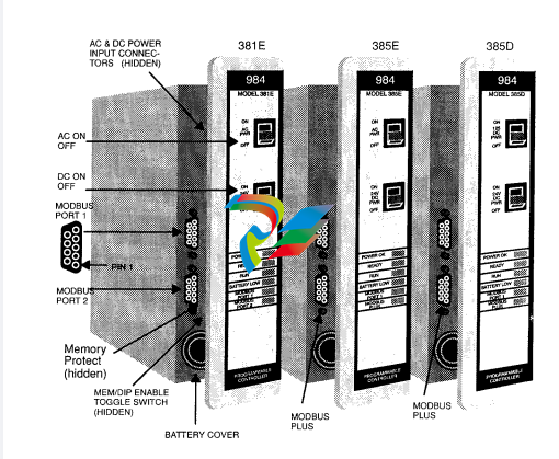
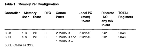
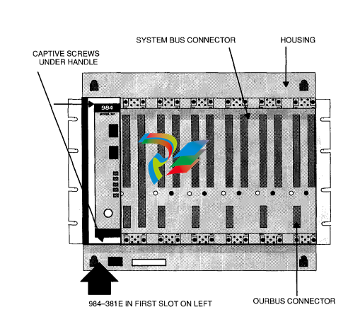
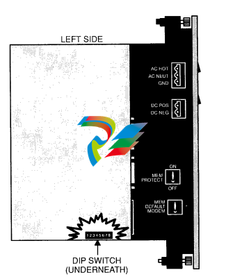
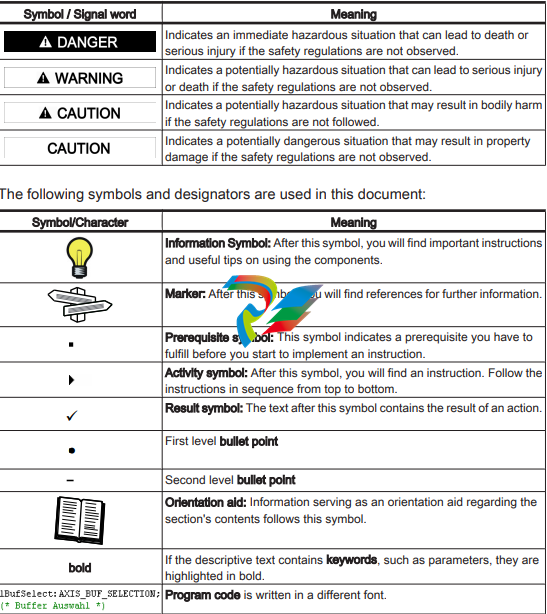
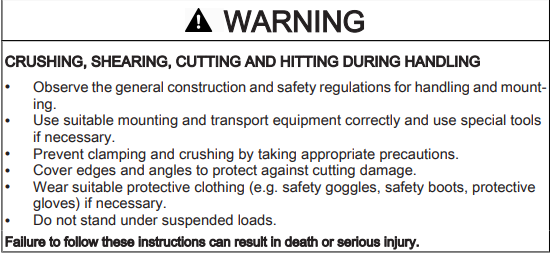
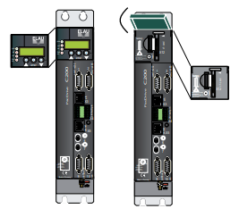
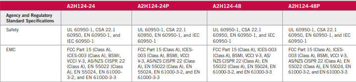
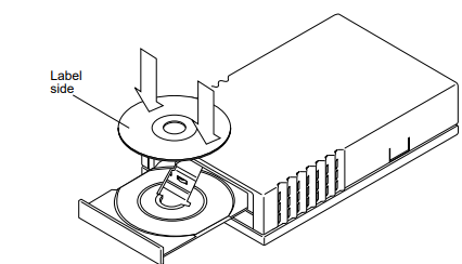
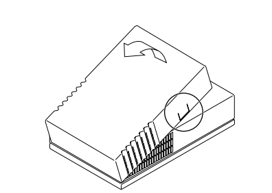
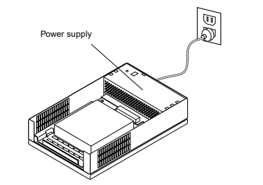
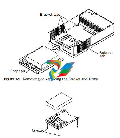
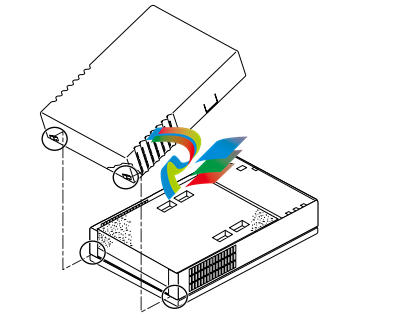
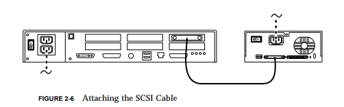 2. Turn on the power to the peripherals and the workstation