Read this document and the documents listed in the additional resources section about installation, configuration, and
operation of this equipment before you install, configure, operate, or maintain this product. Users are required to familiarize
themselves with installation and wiring instructions in addition to requirements of all applicable codes, laws, and standards.
Activities including installation, adjustments, putting into service, use, assembly, disassembly, and maintenance are required to
be carried out by suitably trained personnel in accordance with applicable code of practice.
If this equipment is used in a manner not specified by the manufacturer, the protection provided by the equipment may be
impaired.
In no event will Rockwell Automation, Inc. be responsible or liable for indirect or consequential damages resulting from the use
or application of this equipment.
The examples and diagrams in this manual are included solely for illustrative purposes. Because of the many variables and
requirements associated with any particular installation, Rockwell Automation, Inc. cannot assume responsibility or liability for
actual use based on the examples and diagrams.
No patent liability is assumed by Rockwell Automation, Inc. with respect to use of information, circuits, equipment, or software
described in this manual.
Reproduction of the contents of this manual, in whole or in part, without written permission of Rockwell Automation, Inc., is
prohibited.
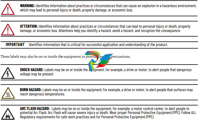
Throughout this manual, when necessary, we use notes to make you aware of safety considerations.
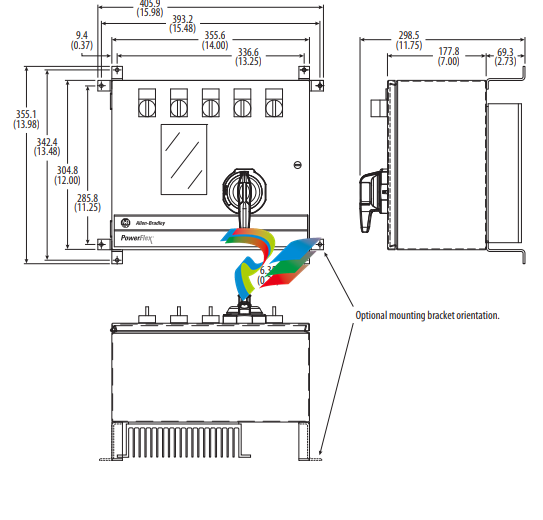
About This Publication This document provides procedural information for managing daily or
recurring tasks involving the PowerFlex® 7000 medium voltage ‘B’ frame
drives (heatsink and heatpipe models).
Download Firmware, AOP,
EDS, and Other Files
Download firmware, associated files (such as AOP, EDS, and DTM), and access
product release notes from the Product Compatibility and Download Center at
rok.auto/pcdc.
Summary of Changes This publication contains the following new or updated information. This list
includes substantive updates only and is not intended to reflect all changes.
Who Should Use This
Manual
This manual is intended for use by personnel familiar with medium voltage
and solid-state variable speed drive equipment. The manual contains material
that enables regular operation and maintenance of the drive system.
What Is Not in This Manual This manual provides information specific to maintaining the PowerFlex 7000
‘B’ frame drive. This document does not include topics such as:
• Physically transporting or siting the drive cabinetry
• Installing or commissioning procedures
• Spare parts lists compiled for your order.
Rockwell Automation provides the site- and installation-specific electrical and
design information for each drive during the order process cycle. If they are
not available on site with the drive, contact Rockwell Automation.
If you have multiple drive types or power ranges, ensure you have the correct
documentation for each specific PowerFlex 7000 product:
• ‘A’ frame for lower-power air-cooled, configurations (up to
approximately 1250 hp/933 kW)
• ‘B’ frame for higher-power, air-cooled configurations (standard or
heatpipe models)
• ‘C’ frame for all liquid-cooled configurations
PowerFlex 7000 Drive Overview
The PowerFlex™ 7000 drive is a general-purpose, standalone, medium voltage
drive that controls speed, torque, direction, starting, and stopping of standard
asynchronous or synchronous AC motors. This drive works on numerous
standard and specialty applications such as fans, pumps, compressors, mixers,
conveyors, kilns, fan-pumps, and test stands in industries such as
petrochemical, cement, mining and metals, forest products, power generation,
and water/waste water.
The PowerFlex 7000 drive meets most common standards from these
organizations:
• National Electrical Code (NEC)
• International Electrotechnical Commission (IEC)
• National Electrical Manufacturers Association (NEMA)
• Underwriters Laboratories (UL)
• Canadian Standards Association (CSA).
The drive is available with the world’s most common supply voltages at
medium voltage, from 2400…6600V. The design focuses on high reliability,
ease of use, and lower total cost of ownership.
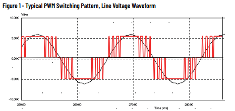
Topology The PowerFlex 7000 drive uses a pulse width modulated (PWM) – current
source inverter (CSI) topology. This topology applies to a wide voltage and
power range. The power semiconductor switches used are easy-to-series for
any medium voltage level. Semiconductor fuses are not required for the power
structure due to the current limiting DC link inductor.
With 6500V PIV rated power semiconductor devices, the number of inverter
components is minimal. For example, only six inverter switching devices are
required at 2400V, 12 at 3300…4160V, and 18 at 6600V.
The PowerFlex 7000 drive also provides inherent regenerative braking for
applications where the load is overhauling the motor, or where high inertia
loads are quickly slowed down. The drive uses the following:
• Symmetrical gate commutated thyristors (SGCTs) for machine converter
switches
• SGCTs for active front-end (AFE) rectifier configurations for the line
converter switches
• Silicon-controlled rectifiers (SCRs) for 18-pulse rectifier configurations
The PowerFlex 7000 drive provides a selectable option for enhanced torque
control capabilities and increased dynamic control performance. This highperformance torque control (HPTC) feature delivers 100% torque at zero speed
and provides torque control through zero speed with smooth direction
transition.
Rectifier Designs Configurations
The PowerFlex 7000 drive offers three rectifier configurations for ‘B’ frame
drives:
• Direct-to-Drive™ (AFE rectifier with integral line reactor and CMC)
• AFE rectifier with separate isolation transformer
• 18-pulse rectifier with separate isolation transformer
Direct-to-Drive
Direct-to-Drive technology does not require an isolation transformer or
multiple rectifier bridges as in voltage source inverter (VSI) topologies offered
by others. The approach is completely different. Instead of multiple
uncontrolled rectifiers, a single AFE rectifier bridge is supplied. The rectifier
semiconductors that are used are SGCTs. Unlike the diodes that are used in
VSI rectifier bridges, SGCTs are turned on and off by a gating signal. A PWM
gating algorithm controls the firing of the rectifier devices, similar to the
control philosophy of the inverter. The gating algorithm uses a specific
42-pulse switching pattern called selective harmonic elimination (SHE) to
mitigate the 5th, 7th, and 11th harmonic orders
A small integral line reactor and capacitor addresses the high harmonic orders
(13th and above) and provides virtually sinusoidal input voltage and current
waveforms back to the distribution system. This configuration delivers
excellent line-side harmonic and power factor performance to meet IEEE 519-
1992 requirements and other global harmonic standards in virtually all cases.
This setup also provides a simple, robust power structure that maximizes
uptime by minimizing the number of discrete components and the number of
interconnections required.
A CMC mitigates the common mode voltage seen at the motor terminals, so
standard (non-inverter duty rated) motors and motor cables can be used. This
technology is ideal for retrofitting existing motor applications
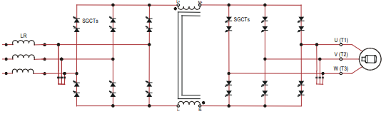
AFE Rectifier with Separate Isolation Transformer
For applications when the line voltage is higher than the motor voltage, a
transformer is required for voltage matching. In this case, providing an AFE
rectifier with a separate isolation transformer is ideal (indoor and outdoor
transformer versions are offered). The isolation transformer replaces the
requirement for an integral line reactor and replaces the requirement for a
CMC that is supplied in the Direct-to-Drive rectifier configuration. However,
the AFE rectifier, its operation, and advantages are the same as the Direct-toDrive configuration.
Figure 3 – 3300/4160 AFE Rectifier with Separate Isolation Transformer
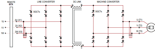
For high power constant torque applications and/or when the line voltage is
higher than the motor voltage, a transformer is required for voltage matching
(indoor and outdoor transformer options are available). The 18-pulse rectifier
uses SCRs instead of the SGCTs used for an AFE rectifier. When used for high
power constant torque applications, the 18-pulse rectifier has lower losses than
the AFE rectifier, making 18-pulse ideal for the highest power requirements.
The 18-pulse isolation transformer provides the required input impedance and
addresses common mode voltage just like the separate isolation transformer
used with the AFE rectifier. However, instead of a PWM rectifier switching
pattern and a single rectifier bridge, the 18-pulse configuration mitigates line
side harmonics through harmonic current cancellation in the isolation
transformer phase shifted secondary windings. The inverter is the same
configuration for all available rectifier options.
Figure 4 – 3300/4160V 18-pulse Rectifier with Separate Isolation Transformer
Cooling Technology These VFDs are supplied with heatsinks for most configurations and heatpipes
for the highest-power AFE configurations. While both configurations draw
heat away from the semiconductors, heatpipes are bigger, more efficient, and
require larger fans and airflow.
Information and graphics in this manual show both configurations.
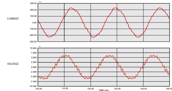
Motor Compatibility The PowerFlex 7000 drive achieves near-sinusoidal current and voltage
waveforms to the motor, resulting in no significant additional heating or
insulation stress. Temperature rise in the motor connected to the VFD is
typically 3 °C (5.5 °F) higher compared to across-the-line operation. Voltage
waveform has dv/dt of less than 50 V/μs. The peak voltage across the motor
insulation is the rated motor RMS voltage divided by 0.707.
Reflected wave and dv/dt issues often associated with VSI drives are a nonissue with the drive. Figure 5 shows typical motor waveforms. The drive uses a
SHE pattern in the inverter to eliminate major order harmonics, plus a small
output capacitor (integral to the drive) to eliminate harmonics at higher
speeds.
Standard motors are compatible without de-rating, even on retrofit
applications.
Motor cable distance is virtually unlimited. Rockwell Automation has tested
this technology for controlling motors up to 15 km (9.3 mi) away from the drive.
Figure 5 – Motor Waveforms at Full Load, Full Speed
Power Component Definition and Maintenance
This section provides an overview of the control components and cabling of
your PowerFlex® 7000 ‘B’ frame drive. This section also details a number of
regular or recurring maintenance tasks that will keep your drive in peak
operating condition.
Figure 20 through Figure 26 identify the control components and cabling of
your drives. Where appropriate, separate diagrams and instructions are
available for both the heatsink and the heatpipe ‘B’ frame models.
For information regarding power wiring and cabling connections (as might be
necessary for routine maintenance), see the PowerFlex 7000 ‘B’ frame
installation manual, publication 7000-IN007.
Control Power Off Tests Perform the following checks before applying control power to the drive.
Rockwell Automation recommends that you complete these checks in the
sequence they are presented here.
Interlocking
When the input contactor option is purchased, a key interlock is provided to
prevent access to the medium voltage compartments of the drive unless the
input isolation switch is locked in the open position.
Where the input switching device is provided by others, Rockwell Automation
will provide a key interlock on the medium voltage compartment of the drive,
and a matching interlock for installation by others on the upstream device. The
interlock shall be installed in a manner that ensures the power to the drive is
off and the drive is electrically isolated whenever the key is freed.
Although key interlocks shipped with all medium voltage equipment are
aligned in the factory, they often move out of position during shipping or are
often misaligned when the cabinet is set down on an uneven floor.
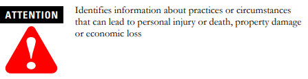
ATTENTION: Servicing energized industrial control equipment can be
hazardous. Severe injury or death can result from electrical shock,
burn, or unintended actuation of control equipment. Hazardous
voltages can exist in the cabinet even with the circuit breaker in the
off position. We recommend that you disconnect or lock out control
equipment from power sources, and confirm discharge of stored
energy in capacitors. If you must work in the vicinity of energized
equipment, the safety-related work practices of NFPA 70E, Standard
for Electrical Safety in the Workplace, must be followed
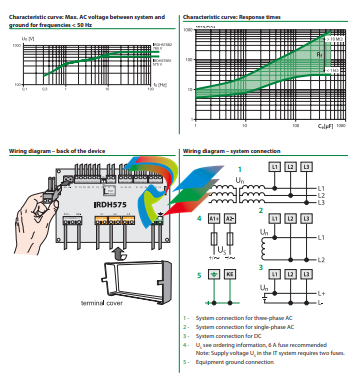
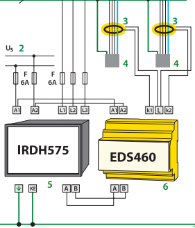
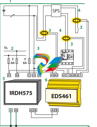
The IRDH575 monitors for ground faults in ungrounded AC (20 – 760 V, single- and threephase) and DC (20 – 575 V) by measuring the system’s insulation resistance. Systems with
extensive power conversion devices, such as rectifiers and variable frequency drives, are
supported by the IRDH575. The IRDH575 is able to detect ground faults in ungrounded
systems before leakage current may even be present.
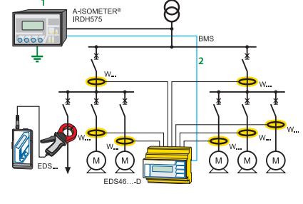
When combined with EDS4… ground fault location devices and the appropriate current
transformers, the IRDH575 becomes a controller for a ground fault location system.
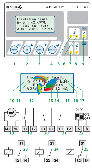
Function: Ground fault detection
When the insulation resistance from system to ground falls below the set response value,
the alarm relays switch and the alarm LEDs activate. Two separately adjustable alarm
contacts can be set to a prewarning and main warning alarm. The measured value is indicated on the LCD display or on an externally connected meter. If the device is set to nonlatching mode, the alarms will clear when the ground fault clears. If the device is set to
latching mode, the alarms will not reset until the device is reset manually or the supply
voltage is lost. An external and internal test/reset can be activated remotely or on the device. A comprehensive INFO menu key displays additional information such as the current leakage capacitance and device settings.
The IRDH575 continuously monitors the equipment ground connection and line connections to ensure proper operation. The device’s easy-to-use onboard menu manages all
settings via the detailed LCD screen.
Function: Ground fault location
When a ground fault is detected, the EDS ground fault location system is activated (this
feature can be set to require a manual start as well). Each channel of the EDS location device is connected to a particular branch circuit. The IRDH575 begins transmitting a pulsed
signal. This signal will travel through the channel of the EDS with the ground fault back
to the IRDH575. If the pulse travels back to the IRDH575, the channel with the ground
fault will display on both the IRDH575 and the EDS device.
In addition, an optional EDS30… portable ground fault location system can be used to follow the pulse travelling to the source of the ground fault.
Additional functions
99 timestamped alarm messages may be stored in the non-volatile memory of the
IRDH575. The device also includes standby contacts when several A-ISOMETER® detectors
are operating in coupled ungrounded systems.
Two-way data communication is carried out between devices via an RS-485 interface.
This interface can be connected to a BENDER protocol converter to exchange data across
other protocols, such as Ethernet, MODBUS, or PROFIBUS.
A 0/4 – 20 mA output can be connected to an external meter or higher-level control system, such as a PLC.
System design
Each isolated system requires one IRDH575 for ground fault detection and location control. Up to 90 EDS46… devices can be interconnected to the IRDH575. Each EDS device
can monitor up to 12 separate channels. An optional EDS30…. portable ground fault location system can be used in conjunction with the IRDH575/EDS46… system.
1 – INFO key: Displays pertinent system information
This manual does not contain all the information required to operate and maintain
the product. Refer to the following manuals for other required information.
3500 Monitoring System Rack Configuration and Utilities Guide
(129777-01)
• guidelines for using the 3500 Rack Configuration software for setting the operating
parameters of the module
• guidelines for using the 3500 test utilities to verify that the input and output
terminals on the module are operating properly
3500 Monitoring System Computer Hardware and Software Manual
(128158-01)
• instructions for connecting the rack to 3500 host computer
• procedures for verifying communication
• procedures for installing software
• guidelines for using Data Acquisition / DDE Server and Operator Display Software
• procedures and diagrams for setting up network and remote communications
3500 Field Wiring Diagram Package (130432-01)
• diagrams that show how to hook up a particular transducer
• lists of recommended wiring
Operation and Maintenance Manuals for all the modules installed in the
rack
Product Disposal Statement
Customers and third parties, who are not member states of the European Union, who are
in control of the product at the end of its life or at the end of its use, are solely
responsible for the proper disposal of the product. No person, firm, corporation,
association or agency that is in control of product shall dispose of it in a manner that is
in violation of any applicable federal, state, local or international law. Bently Nevada LLC
is not responsible for the disposal of the product at the end of its life or at the end of its
use.
1. Receiving and Handling Instructions
This will be a short overview of the entire section.
1.1 Receiving Inspection
Visually inspect the system for obvious shipping damage. If you detect shipping
damage, file a claim with the carrier and submit a copy to Bently Nevada, LLC.
1.2 Handling and Storage Considerations
Proper handling and storing of printed circuit boards is extremely critical. Circuit
boards contain devices that are susceptible to damage when exposed to
electrostatic charges. Damage caused by obvious mishandling of the board will
void the warranty. To avoid damage, observe the following precautions in the
order given.
Application Advisory
Machinery protection will be lost when
you remove all power from the rack.
• Do not discharge static electricity onto the circuit board. Avoid tools or
procedures that would subject the circuit board to static damage.
Some possible causes of static damage include ungrounded soldering
irons, nonconductive plastics, and similar materials.
• Use a suitable grounding strap (such as 3M Velostat® No. 2060) to
ground yourself before handling or performing maintenance on a
printed circuit board.
• Transport and store circuit boards in electrically conductive bags or
foil.
• Use extra caution during dry weather. Relative humidity less than 30%
tends to multiply the accumulation of static charges on any surface.
When performed properly, you may remove modules from or install modules into
the rack while power is applied to the rack. Refer to << Section reference to
“Module Installation in section 4 >> for the proper procedure
2. General Information
Monitoring and computerized vibration information systems provide the
information you need to assess the mechanical condition of rotating and
reciprocating machinery. These systems continuously measure and monitor
various supervisory parameters and provide crucial information for early
identification of machinery problems such as imbalance, misalignment, shaft
crack, and bearing failures. As such, these systems are an efficient and effective
means of satisfying plant management, engineering, and maintenance concerns
for:
• Increasing plant safety by minimizing the occurrence of hazardous
conditions or catastrophic failures.
• Improving product quality by minimizing process variances caused by
improperly operating equipment.
• Maximizing plant availability by servicing only those machines that
require it and providing more efficient turnarounds.
• Reducing plant operating costs by minimizing unplanned shutdowns
and by making more efficient use of maintenance resources.
For protection of critical machinery, we highly recommend that you permanently
install continuous monitoring systems. The term “protection” means that the
system can shut down machinery on alarm, without human interaction. These
systems include applicable transducers, each with its own dedicated monitoring
circuitry and alarm setpoints. The 3500 Monitoring System is the newest addition
to the family of continuous monitoring systems offered by Bently Nevada, LLC.
2.1 3500 Monitoring System
The 3500 is a full-feature monitoring system whose design incorporates the latest
in proven processor technology. In addition to meeting the above stated criteria,
the 3500 adds benefit in the following areas:
• Enhanced operator information
• Improved integration to plant control computer
• Reduced installation and maintenance cost
• Improved reliability
• Intrinsic Safety (IS) option
The following sections discuss these benefits in more detail.
2.1.1 Enhanced Operation Information
The 3500 design includes features to both enhance the operator’s information
and present this information so that the operator may easily interpret it. These
features include:
• Improved data set
– Overall amplitude
– Probe gap voltage
– 1X amplitude and phase
– 2X amplitude and phase
– Not 1X amplitude
• Windows®-based Operator Display Software
• Data displayed at multiple locations
2.1.2 Improved Integration to Plant Control Computer
The 3500 improves integration to the plant control computer with:
• Communication Gateways supporting multiple protocols
• Time synchronized vibration and process information
2.1.3 Reduced Installation and Maintenance Costs
The 3500 system provides the following cost-saving features:
• Reduced cabling costs
• Downward product compatibility
• Improved space utilization
• Easier configuration
• Reduced spare parts
• Improved serviceability
2.1.4 Improved Reliability
The 3500 offers several features to improve system reliability.
• Redundant power supplies available
• Triple Modular Redundant (TMR) monitors and relay cards available
• Redundant Gateway and Display Modules permitted
2.1.5 Intrinsic Safety Option
If you wish to monitor equipment that is located in hazardous atmospheres, the
3500 Monitoring System has a range of I/O modules with internal zener barriers.
These modules provide an Intrinsically Safe interface between the 3500 rack and
the transducers located in the hazardous area.
2.1.6 Multiple Output Interfaces
You can conveniently adjust monitor options (such as full scale ranges,
transducer inputs, recorder outputs, alarm time delays, alarm voting logic, and
relay configuration) in the field via software. Modular system design employs
plug-in components which allow easy servicing and expansion.
The following three independent interfaces are available with the 3500 system:
• Data Manager Interface (Transient Data Interface External or Dynamic
Data Interface External)
• Configuration/Data port
• Communications Gateway (support for Programmable Logic
Controllers, Process Control Computers, Distributed Control Systems,
and PC-based Control Systems)
These interfaces allow you to easily view monitored parameters and their
statuses in the following ways:
• System 1® Software
• Bently Nevada™ 3500 Operator Display Software
• Remote display panel
• DCS or PLC display
Convenient front panel coaxial connectors provide dynamic transducer signals
and allow you to connect diagnostic or predictive maintenance instruments.
2.2 Common Features
The common features of the modules in the 3500 rack include hot insertion or
removal of modules and external and internal termination of the wiring.
2.2.1 Hot Insertion or Removal of Modules
When performed properly, you can remove and replace any module while the
system is under power without affecting the operation of any unrelated modules.
If the rack has 2 power supplies, removing or inserting a power supply will not
disrupt the operation of the 3500 rack. See <<Section reverence: “Module
Installation in section 4 >> for the proper procedure.
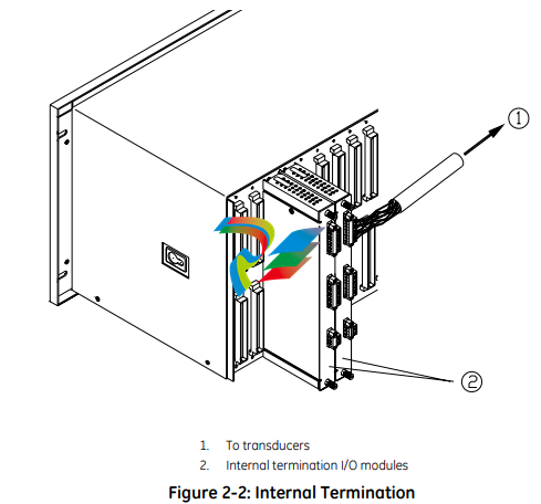
2.2.2 External and Internal Termination
External termination uses multi-conductor cables to connect the I/O modules to
the terminal blocks. These blocks simplify connecting many wires to the rack in
tight areas. External termination is not available on I/O modules with internal
zener barriers.
Internal termination lets you connect transducers directly to the I/O modules.
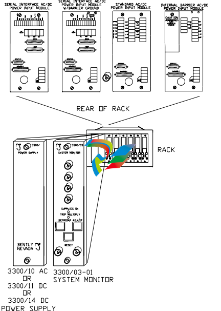
3500 System Components
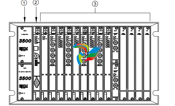
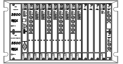
The 3500 Monitoring System consists of modules that fit into a rack. Figure 2-3
shows a full-size 3500 system rack and system components. Note that the fullsize rack has 14 monitor slot positions. The Mini-rack (not shown) is similar, but
has 7 monitor slot positions to the right of the power supplies and Rack Interface
Module.
1. 1 or 2 power supplies
2. Rack Interface Module (standard, Transient Data Interface, (TDI), Triple Modular Redundant (TMR) and TMR TDI)
3. Monitoring slot positions:
– Monitor module
– Keyphasor® module (2 maximum)
– Relay module
– Communication Gateway module
– Display module. For the System Face Mount you must install the Display Interface Module in Slot 15.
– 3500/04-01 Earthing Module. Intallations that use Inernal Barrier I/Os require 1 Earthing Module per rack.
Figure 2-3: 3500 Rack (Full-Size)
The following sections list the function of each module. Refer to the individual
operation and maintenance manuals for available options, detailed description,
operation and maintenance.
2.3.1 Weatherproof Housing
The weatherproof housing protects the 3500 rack from adverse environmental
effects, such as excessive moisture, dirt and grime, and even unclean air. The
weatherproof housing will not accommodate a Display Unit or VGA Display.
2.3.2 Rack
2 types of 3500 racks are available: the full-size 19-inch rack and the compact 12-
inch Mini-rack. Each rack requires you to install the Power Supplies and Rack
Interface Module (RIM) in specific locations. The full-size version offers 14
additional rack positions and the Mini-rack offers 7 additional rack positions. You
may use these positions to install any combination of modules. Both racks
support Standard (non-redundant) and Triple Modular Redundant (TMR)
configurations
Application Advisory
The TMR system will restrict the
location of certain modules.
2.3.3 Power Supply
The Power Supply is a half-height module available in ac and dc versions. You
can install 1 or 2 power supplies in the rack. Each power supply can power a fully
loaded rack. When you install 2 power supplies in a rack, the supply in the lower
slot acts as the primary supply and the supply in the upper slot acts as the
backup supply. If the primary supply fails, the backup supply will provide power to
the rack without interrupting rack operation. The 3500 design allows you to
install any combination of power supply types.
Overspeed Detection and TMR Monitors require dual power supplies.
2.3.4 Rack Interface Module
The Rack Interface Module (RIM) is a full-height module that communicates with
the host (computer), a Bently Nevada™ Communication Processor, and the other
modules in the rack. The Rack Interface Module also maintains the System Event
List and the Alarm Event List. You can daisy-chain this module to the Rack
Interface Modules in other racks and to the Data Acquisition / DDE Server
Software. The 3500 Monitoring System Computer Hardware and Software Manual
shows how to daisy chain the Rack Interface Modules together. Rack Interface
Modules are available in Standard, Triple Modular Redundant and Transient Data
Interface versions.
2.3.5 Communication Gateway Module
The Communication Gateway Module is a full-height module that allows external
devices (such as a DCS or a PLC) to retrieve information from the rack and to set
up portions of the rack configuration. You can install more than one
Communication Gateway Module in the same rack. Communication Gateway
Modules are available for a variety of network protocols.
2.3.6 Monitor Module
The Monitor Modules are full-height modules that collect data from a variety of
transducers. You can install any combination of Monitor Modules in the 3500
rack.
2.3.7 Relay Module
Relay Modules provide relays that you can configure to close or open based on
channel statuses from other monitors in the 3500 rack. Relay modules are
available in 4-channel, 16-channel, and 4-channel Triple Modular Redundant
(TMR) versions.
The TMR Relay Module is a half-height 4-channel module that operates in a TMR
system. 2 half-height TMR Relay Modules must operate in the same slot. If you
remove the upper or lower Relay Module or the system declares one of the
modules as Not OK, then the other Relay Module will control the Relay I/O Module.
2.3.8 Keyphasor® Module
The Keyphasor Module is a half-height module that provides power for the
Keyphasor transducers, conditions the Keyphasor signals, and sends the signals
to the other modules in the rack. The Keyphasor Module also calculates the rpm
values sent to the host (computer) and external devices (DCS or PLC) and provides
buffered Keyphasor outputs. Each Keyphasor Module supports 2 channels. You
may place up to 2 Keyphasor Modules in a 3500 rack for a maximum of 4
Keyphasor channels. If you use 2 Keyphasor Modules, you must place them in the
same full-height slot and the modules will share a common I/O module.
2.3.9 Display Module
The 3500 system offers multiple display options.
The Display Interface Module can display rack data on an LCD-based Interface
unit or a 3rd-party Modbus® based display unit.
The VGA Display Module will display rack data on certain touch screen VGA
Displays.
The Integrated PC display is a complete rack mount touch screen PC pre-loaded
with rack configuration software and display utilities.
2.3.10 Earthing Module
The Earthing Module is a full-height module that provides a low resistance
connection (must be less than 1 Ω) from the 3500 rack to the plant’s intrinsically
safe earth ground. The module operates in conjunction with the 3500 internal
zener barrier I/O modules. Your application will require 1 Earthing Module per rack
when internal barrier I/O modules are used.
2.4 Standard Rack Relay Options
You can configure the standard (or non-TMR) 3500 rack to have individual relays,
bussed relays, or a combination of individual and bussed relays.
2.4.1 Individual Relays
A rack with individual relays contains 1 or more relay cards for each monitor
module. You can configure the monitor and relay modules within a 3500 rack in
many ways.
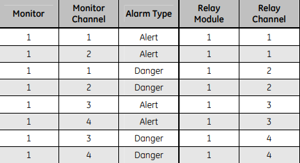
Example 1: The application uses 1 relay module 1 monitor module
Table 2-1: 1 Relay Module Used With 1 Monitor Module
Figure 2-4: Typical Standard 3500 Rack with Individual Relays (Full-Size Rack Shown)
2.4.2 Bussed Relays
In the Bussed Relays configuration a number of monitor channels share a single
relay. Use the Rack Configuration Software to define the combination of alarms
that will trigger the relay. Figure 2-5 shows a typical Bussed Relay layout for a
standard 3500 rack. You can [place the monitors and relay modules in any slot as
long as you link the monitors to the relay module in the Rack Configuration
Software
3.7.4 Additional Notes
• Larger scale factors are less susceptible to EMI than smaller scale factors.
• Larger full-scales are less susceptible to EMI than smaller full-scale.
• Monitors with narrow bandwidth filter configurations are less susceptible to
EMI than monitors configured with wide bandwidth.
• Larger Keyphasor® or hysteresis settings are less susceptible to EMI than
smaller hysteresis settings.
• Shorter Alarm delay times may increase monitor susceptibility to transient
EMI.
• Environments with higher levels of EMI than tested may cause unpredictable
monitor readings and may cause system malfunction.
3.8 Set Rack Jumpers and Switches
Set the following jumpers and switches before operating the rack:
• Rack address switch (on the front of the Rack Interface Module)
• Transducer jumpers on each I/O Module, as required
• Certain I/O Modules have switches to control their mode of operation.
Examples include:
– RIM and Comm Gateway I/O’s that support both RS232 and
RS422 have a protocol selection switch
– Overspeed and non-TMR Relay I/O’s have Normally
Energized/De-energized Relay mode switches
– Comm Gateway I/O’s that support RS485 have termination
mode switches
• Setup phone connection to rack / host (if you use an internal or
The GE Multilin 515 Blocking and Test Module has the following features:
• 14 Pole switchbank
• CT inputs short when current switches are opened
• Current injection for each phase
• Ground terminal
• Ability to visually isolate (open) trip relay output circuits
• Cover provided
• Suitable for utility and industrial use
• 515 test plugs available
Description
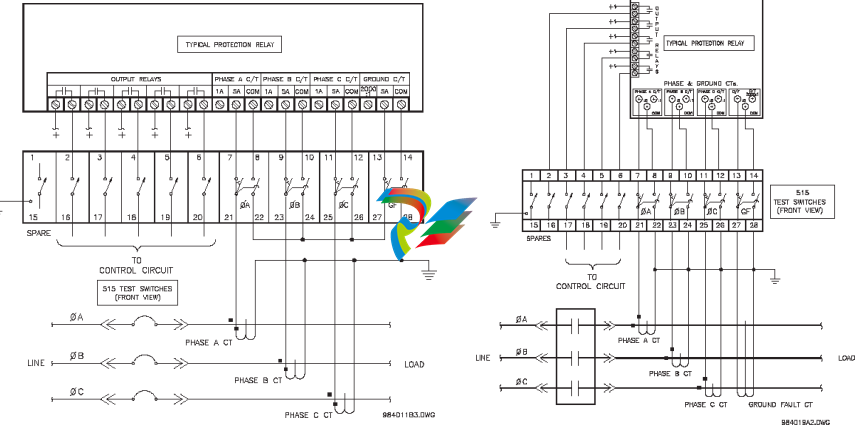
The 515 Blocking and Test Module provides an effective means of trip blocking, relay isolation and testing of GE Multilin relays. By opening the
switches and inserting test plugs, phase and residual currents from the primary CTs can be monitored. Currents can be injected into the relay from
a secondary injection test set during commissioning.
Prior to testing, the trip and auxiliary circuits must first be opened to prevent nuisance tripping; CTs can then be shorted. Conversely, when the test
is complete and the relay put back into operation, the CT switches should be closed first to ensure normal operation of the relay, prior to closing
the trip and auxiliary circuits.
Installation
Shorting switches are provided for connection of 3 phase CTs (current transformers) and a separate core balance ground fault CT or 3 phase CTs
connected for residual ground fault sensing.
When each CT switch is opened, the CT is shorted. It is essential that the CT is connected to the shorted side of the switch as shown in the following
figure, otherwise dangerously high voltages would be present from the open circuited CTs.
When the switches are open, test plugs can be inserted to either inject signals into the relay wired to the switches or monitor signals such as CT
current from the switchgear.
Figure 1: Typical wiring for connecting a 515 to a protective relay Figure 2: Typical Wiring for Zero-Sequence Ground Fault
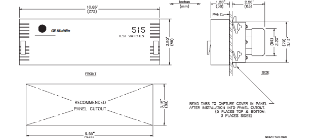
The 515 Blocking and Test Module consists of a metal chassis attached to the 515 test switches that slides into the panel. A single cutout in the panel, as per the dimensions shown in Figure 3, is required to mount the 515 test switches.
Slide the metal chassis attached to the 515 test switches into the cutout from the front of the panel. While firmly applying pressure from the front of the 515
module to ensure the chassis fits snugly, bend out the retaining tabs as shown in Figure 3. Usually the retaining tabs will be sufficient to hold the 515
module securely in place. If additional fastening is desired bend out the clamping screw tabs at both ends of the chassis at right angles. Insert the #8
screws provided in the accessory pouch into the tapped holes with the vibration proof nut between the tab and the panel. Tighten each screw until the end
of the screw butts firmly against the front panel. Ensure the nut is installed tightly against the bent tab. Nylon inserts in these nuts prevent them from
vibrating loose. The 515 test switch module should now be securely mounted to the panel with no movement ready for rear terminal wiring. When
completed, place the front cover over the mounted 515 test module and turn the fasteners at both ends ¼ turn to lock it in place, as shown in Figure 3.
As a safety precaution, a ground screw located on the bottom-right of the rear side of the module is available to be connected to panel chassis ground.
Operation
To put the 515 Blocking & Test Module into operation, additional parts have been provided:
• 1 package containing at least 28 terminal nuts
• 14 white tags for identification of each of the switches
The 515 provides a means of trip blocking, relay isolation, and testing of GE Multilin relays. The 515 accomplishes this with a total of 14 switches. There are 6
single pole throw switches for use with the output relays, and 4 groups of 2 switches each for use with the current transformers as illustrated in Figure 1:
Typical Wiring.
Isolation or opening of the relay’s output circuits is accomplished with the six switches at terminals 1 through 6 and 15 through 20.
These switches can be used to simply open the protection relay’s output contacts and thus provide a means of blocking trips. The
4 remaining groups of 2 switches at terminals 7 through 14 and 21 through 28 are used for shorting of the CT inputs, injection of
test current, and measuring of CT current. The four groups correspond to Phase 1 Current, Phase 2 Current, Phase 3 Current, and
Ground Current.
Each group is made up of two switches. The first switch for the Phase 1 group is at terminal 7 and 21 and is configured as shown
on the right:
Note that terminals 7 and 21 are shorted together regardless of whether the switch is
open or closed. The second switch for the Phase 1 group is at terminals 8 and 22. It is
configured as shown on the right:
Note that this switch operates as make before break. When this switch is closed
terminals 8 and 22 are shorted together. When this switch is open, terminals 8 and 22 open and 22 shorts with 7 and 21. This in turn shorts the
Phase 1 CT. It is essential that the CT is connected to the shorted side of the switch as shown on the right.
Otherwise, dangerously high voltages would be present at the open circuited current transformer. Also note that
currents can be injected into the protection relay from a secondary injection test set.
With the switch between terminals 7 and 21 open and the switch between terminals 8 and 22 closed as shown
below, a 515 test plug can be inserted between terminals 7 and 21 to monitor the CT current. See the diagrams
below for details. Note that the 515 test plug is made up of two conductors separated by an insulator