Ovation® Expert Transition for Siemens Teleperm XP Control Systems
Transition to Better Controls From a Better Supplier
Today’s competitive business environment requires optimal performance not only from your power plant generation equipment, but also from your operations and maintenance personnel. Are you currently experiencing any of the following Teleperm XP control system issues that may be prohibiting your plant from optimal operations?
Poor performance and reliability
• Multiple systems for a single power block
• Limited system-to-system communication
• Inadequate product service and support
• High support costs from outdated technology
• Considering TXP replacement after only 3-5 years in service
If yes, then you need a supplier with vast power industry expertise that can provide performance-enhancing technology combined with comprehensive support to optimize your plant operations. That supplier is Emerson.
Are you ready to experience increased satisfaction with better controls and award-winning support services? If so, then make the transition to Emerson and discover why we are the leaders in power generation controls and automation with a full suite of products and services
Use Today’s Technology While Preserving Yesterday’s Investments
Transition your Teleperm XP control systems to proven Ovation technology for enhanced turbine operations. Emerson migration programs have been proven to reduce project costs and improve plant operations in hundreds of installations on various control system platforms, even those from other vendors.
Key to our transition strategy is an integrated Ovation Profibus® DP I/O module that interfaces directly to the Profibus DP communication network used in the Teleperm XP system to connect with the ET200M I/O. Our solution provides your operators complete control and monitoring capabilities from a single Ovation system, without starting over. Your transition choices include retaining your existing I/O, terminations, and field wiring – or migrating your entire legacy TXP system to Ovation for a complete technology upgrade.
Emerson’s transition program includes a total replacement of the embedded Teleperm XP SIMADYN system with native Ovation turbine I/O modules, enabling quicker response times and tighter controls. Our turbine I/O was designed specifically to handle unique control requirements such as turbine speed pickups, fast closed-loop positioning of major servo-operated valves, and interfacing to electro-hydraulic servo valve actuators.
Use of fully-redundant I/O interface modules and high-speed Ovation Controllers, with proven logic such as 2-out-of-3 testable manifolds assures the highest level of reliability, performance, and safety for your demanding gas and steam turbine operations.
The Emerson solution:
• Retains your existing Teleperm XP I/O
• Reuses existing terminations and associated wiring
• Replaces the entire TXP SIMADYN sub-system with fully integrated Ovation Turbine I/O modules
• Includes full support for turbine OEM control-related Product Modifications (Prod Mods)
“Great service, teamwork, and cooperation are the benchmarks of your organization, but I believe that the Emerson team at Dunkirk exceeded even those expectations on a daily basis.” — Bill Vogel, Instrumentation & Controls Supervisor, Dunkirk Power Plant, NRG
Put Decades of Turbine Expertise to Work for You
Our Emerson’s transition strategy is based on a 40-year foundation of engineering, installing, and servicing new and retrofitted turbine controls around the world. Over 30 of those years includes experience as the primary gas and steam turbine control supplier for units provided by the former Westinghouse Power Generation Business Unit (PGBU). Emerson has designed and manufactured numerous turbine control platforms and associated control applications. Our tradition of supplying innovative, industry-leading turbine solutions is unmatched in the automation market. Emerson’s dedicated turbine control group includes highly specialized experts who have years of experience with turbines from every major OEM, including Westinghouse, Siemens, GE, ABB, and more. Our engineers possess the knowledge and capabilities to help you incorporate turbine OEM Product Modifications into your control system. Emerson’s turbine control solutions combine state-of-the-art technology, excellent project implementation, and dedicated customer service to provide you with maximum availability today, tomorrow, and in the years to come — so you get the best performance out of your existing assets while extending life cycle
The Emerson Advantage• Low-risk, U.S.-based Provider Emerson, headquartered in St. Louis, Missouri, is a recognized leader with a foundation of business excellence, a long history of financial stability, and award-winning brands such as PlantWeb®, Ovation, Fisher, and Rosemount. • Power Generation Focused With more than 40 years of proven experience, the Power & Water Solutions division is Emerson’s designated Center of Excellence for the power generation industry. We specialize in total plant control systems and applications for boilers, HRSGs, steam and gas turbines, balance of plant, optimization, simulation, and consulting services. • Ovation – Designed for Power Generation Specifically designed to optimize the power generation industry, one Ovation system offers a unified control platform for all your power plant requirements, providing your personnel with consistent and simplified operations and maintenance. • Committed OEM Implementation Support Emerson is 100% committed to providing controls-related turbine OEM Product Modification (Prod Mods) support throughout your Ovation system life cycle. • High Customer Satisfaction A recent independent survey placed Emerson’s customer satisfaction at better than 97%. Emerson has been singled out for consistently helping our customers to achieve superior operational efficiencies
1. The Ovation Controller controls the switching of the resident’s telephone lines as well as door control and communications with the visitor. The “S” series is the simplest system and uses the same housing as our Spectrum System. The “V” series is similar to the “S”, except it has an integral, lighted directory and uses the same housing as our Vista System. Both the “S” and “V” series are available in handset and hands free models. The “S” and “V” series units are mounted at the entrance of the building or complex. It contains a main processor board and, if the unit is a hands-free model, a hands-free board. The “LP” (Lobby Phone) series uses the same controller as the “S” and “V” systems mentioned above, but instead it is housed in a plain NEMA-type enclosure which is mounted in the telephone room or utility closet. In order for a visitor to call the resident, one of two features is installed on the auxiliary port of the controller board; a tone dial telephone or a Vandal-Proof Panel (option). The tone dial telephone is installed in an indoor, lobby area and is used for calling a resident in the building or for gaining entry to the building by dialing entry codes. The Vandal-Proof Panel is a vandal-resistant door unit which is installed next to the entrance of the building or complex (see number 3 below for more details). There is also a Lobby Phone feature which can be used in addition to the “S” and the “V” series of systems. This feature can be used in the handset or in the hands-free models. The controller for each of these systems is then connected to a chain of Line Interface Boards, each of which is connected to as many as twelve resident telephone lines.
2. The Line Interface Boards (LIBs) allow each resident’s telephone line to be connected to the Ovation Controller when a visitor wants to contact that resident. At all other times, the resident’s telephone line is connected directly to the telephone company. The Line Interface Boards are contained in an LIB housing which is mounted somewhere inside the building, usually close to the telephone junction box.
3. The Vandal-Proof Panel (option) is located at the entrance of the building/complex and is used in door control and communications with the visitor. The Vandal-Proof Panel is enclosed in a vandalresistant stainless steel enclosure with an audio board and keypad inside. This unit is connected to the auxiliary port on the Ovation controller board. The Ovation System is capable of carrying out the following functions (several of these functions are optional, so check with your dealer to determine which capabilities have been included in your system): 1. Visitor entry: When the visitor presses a “#” key on the controller’s keypad followed by the resident’s directory code, this switches the selected resident’s telephone line to the controller and rings the resident’s telephone. The resident can then communicate with the visitor and allow entry at the main door or gate by dialing a “9” on a tone or pulse dialing telephone. If the system is controlling a second door or gate, the resident would dial “5” on a tone or pulse dialing telephone to allow entry at that location. Page 4 of 21 Doc. 6001012 Rev B 2. Call waiting: If the resident’s telephone is in use, he/she will hear 2 short tones to signal that a visitor is attempting to contact him/her. The resident can then dial a “2” and the call in progress will be put on hold and the telephone will be connected to the visitor. If the resident allows entry (as described above), he/she will be automatically switched back to the telephone call in progress. The resident can also deny entry and switch back to the call in progress by dialing a “✱”. Alternatively, if the resident is talking with a visitor and the resident receives a normal phone call, he/she will hear two short tones at which point he/she can put the visitor on hold and switch over to the normal telephone call by dialing a “2” and back again to the visitor by dialing another “2.” 3. Entry codes: Each resident (and any one else you authorize) can have a unique 4-digit entry code. When this code is entered on the controller or lobby phone keypad, it will cause the main door or gate to open. The Ovation can have up to 3,000 entry codes programmed into it.
4. Door monitoring: The installer can place sensors on the door to monitor the status of any door that the system controls. If the door is forced open or held open 60 seconds after it should have been closed, you can program the system to respond in one of the following ways: a. Alarm Call (option)*: The system will first call a pre-programmed outside telephone line and send a message via modem. If there is no modem at the pre-programmed number, whoever answers will hear a series of tones. Pressing any key on their tone dial telephone will acknowledge someone has received the alarm call and the system will connect the answering phone to the system speaker and microphone or ring the Lobby Phone. If the lobby phone is picked up, the answering phone will be connected to the lobby phone. If there is no answer at the pre-programmed number, the system will call the pre-programmed manager lines in their order of priority and report with tones as described above. b. Close a relay: If relay 2 is programmed as an alarm relay, the system will close that relay to activate a device the installer has connected to it (for example, a siren).
5. Free exit through a monitored door: The system can provide free exit through either controlled entry to allow exit without causing a forced open door condition.
6. Access for the Post Office or Fire Department: Connections are included in the system to make certain the post office and fire department can gain access to the building without contacting anyone to allow entry. These features will be connected by the installer and the relevant agency.
7. Direct operator control of doors/gates (option)*: The controlled doors or gates can be activated from the manager’s tone dial or any off site tone dial telephone (using the door/gate control functions requires that the remote programming option be purchased).
8. Remote Programming (option)*: The Ovation System can be remotely programmed from the manager’s tone dial telephone or from any outside tone dial telephone.
9. Remote diagnostics (option)*: The Ovation system can be called using a terminal connected to a Hayes-compatible modem or a personal computer running terminal emulation software. You can then access information concerning the system’s operating parameters, the entry codes programmed into the system, the LIB board numbers used by the system, and the customized directory codes programmed into the system. * These items do not require the installation of a separate reserved telephone line.
ENTERING AND EXITING THE PROGRAM MODE Before you begin programming, your programming source must be activated. Note: Your programming password may not be entered using pulse dial (rotary) telephones. The Ovation can be programmed from one of four programming sources:
1. Keypad mounted to the faceplate: Enter three asterisks (“✱✱✱”) followed by the six digit user defined password (factory set to 000000). The unit will respond with one beep and a “P” will be displayed. If the LP model is installed, the keypad for programming the controller is inside of the enclosure, or the lobby phone may be used (as described in the next section), but no display will be available.
2. Lobby phone keypad: Lift the receiver and enter three asterisks (“✱✱✱”) followed by the six digit user defined password (factory set to 000000). The unit will respond with one beep. PLEASE NOTE: If you have an “LP” model with a Vandal-Proof panel attached, you will not be able to program the system from the Vandal-Proof panel keypad.
3. Manager’s telephone (option)*: Enter three asterisks (“✱✱✱”), the unit ID number, and the six digit user defined password (factory set to 000000). The unit will respond with one beep. The manager’s telephone lines are assigned in step 13. See page 12 for details on the uses of the manager line.
4. Remote telephone (option)*: Dial the manager’s telephone number on a tone dialing telephone and wait for the system to automatically answer and respond with a beep. (The number of rings it will take the system to answer is set in step 05). Enter three asterisks (“✱✱✱”), the unit ID number, and the six digit user defined password (factory set to 000000). The unit will respond with one beep.
+ NOTE: For single unit installations, the unit ID number will always be a “1”. * These features are available to the programmer if the unit was purchased with the remote programming option. See sections 9 and 10 for a more detailed discussion of this option. Once you have completed a programming step and you are finished programming the Ovation system altogether, you need to exit the programming mode for a system to begin working. Follow the steps below to exit the programming mode.
1. To exit the programming mode, press the “✱” key on your programming source.
2. If you are programming from the keypad on the faceplate of the unit, to ensure you have exited the programming mode, a tone will be emitted and the “P” should disappear from the display.
3. If you are programming the Ovation from a source other than the faceplate keypad (i.e. manager’s telephone, lobby telephone, etc…), you will only hear a tone to notify you that you are out of the programming mode.
STEP 67 – TURNING OFF/ON SPECIAL OPTIONS Purpose To have the ability to turn on/off the special options that you have purchased with your system. Format 67 + 1 digit + (0=Off, 1=On) + #. Command 0=Remote Programming Variables 1=Remote Diagnostics 2=Alarm Call 3=Entry Codes 4=Custom Directory Codes and Individual Line Call Waiting Example 67 + 2 + 0 + # (turns off the Alarm Call option for the entire system) Important This area only allows you to control whether you want to enable or disable the options that Notes were purchased with the system. It is not possible to enable a feature that was not purchased with the system through this step. If you wish to view the options which are currently active in your system, press “67” + #. The system will then list the options in the order shown in the “Command Variables” section above. If the system displays a “1” for the option, that option is currently active in your system. If the system displays a “0” for the option, that option is currently not active in your system. If you wish to view the options that were purchased with the system, press “67” + “0” + #. The system will then list the options in the order listed above. If the system displays a “1” for the option, that option was purchased. If the system displays a “0” for the option, that option was not purchased. STEP 52 – RESETTING THE SYSTEM Purpose To have the ability of resetting the system without disconnecting the power to the whole system. This step is only needed if you are adding a unit or an LIB. Format 52 +# Important The system will automatically reset itself once the “52” and “#” have been programmed. Notes
EMERSON Ovation 2 fuel dispenser is a fuel distribution controller, mainly used in fuel distribution systems. It can precisely control the fuel distribution process to ensure the efficiency and accuracy of fuel distribution. The following are some basic usage instructions for the EMERSON Ovation 2 fuel dispenser: System Overview The Ovation 2 fuel dispenser is a fuel distribution controller launched by Emerson and is widely used in various fuel distribution scenarios. This system features high integration and reliability, and can meet the demands of various application scenarios. Hardware Requirements Before installing Ovation 2 fuel dispenser, it is necessary to ensure that the hardware environment meets the following requirements: Server: Multi-core processor, with at least 4 cores recommended; Memory: At least 16GB RAM; Store at least 1TB SSD; Gigabit Ethernet card for network Operating system: Windows Server 2016 or higher version. Client: Multi-core processor, with at least 2 cores recommended; Memory: At least 8GB RAM; Store at least 256GB SSD; Gigabit Ethernet card for network Operating system: Windows 10 or higher version. The software requires operating systems: The Server side should be Windows Server 2016 or a higher version, and the client side should be Windows 10 or a higher version. Database: Microsoft SQL Server 2017 or later. Network: Supports TCP/IP protocol to ensure stable network connection between the server and the client. Installation and Configuration Download the installation package: Visit the official Emerson website or the website of an authorized agent to download the installation package of Ovation 2 fuel dispenser. To install the server side: Run the installation program, select the “Server Side” installation type, configure the database connection, and complete the installation. Install the client: Run the installation program, select the “Client” installation type, configure the server connection, and complete the installation. System configuration: Configure system parameters: Open the Ovation configuration tool, enter the administrator username and password, log in to the configuration tool, and configure basic system parameters such as system name, time zone, and language. Configure control policies: Open the Control Policy editor, create a new control policy, and define the parameters and logic of the control policy. Configure the alarm system: Open the alarm configuration tool, create a new alarm configuration, and define the alarm level and conditions. Configure data collection: Open the data collection configuration tool, create a new data collection configuration, and define the data source and collection cycle. Configure security Settings: Open the Security configuration tool, create a new user or role, and define user permissions and access control. Configure data backup: Open the backup configuration tool, create a new backup configuration, and define the backup policy and storage path. Configure remote access: Open the Remote access configuration tool, create a new remote access configuration, and define the remote access user and port. System test data collection: Start the data collection service to verify whether the data collection is normal. Test control policy: Start the control policy service to verify whether the control policy is executed as expected. Test the alarm system: Start the alarm system service to verify whether the alarm is triggered as expected.
Daily inspection: Regularly check the operating status of the controller to ensure there are no abnormal alarms. Check the network connection to ensure normal data transmission; Check the power supply status to ensure stable power supply. Check the system logs, record and analyze abnormal information. Software update: Before the update, it is necessary to back up the system data, obtain and verify the update package from the official channel, follow the steps to update and then restart the system to verify whether the update was successful. Hardware inspection: Check the hardware status of the controller, network equipment, power supply equipment and input/output modules to ensure their normal operation. In terms of troubleshooting, identify faults: Be familiar with common system fault phenomena, such as controller failure, network communication interruption, etc., and quickly identify the type of fault through alarm information, indicator lights, etc. Troubleshooting: According to the troubleshooting process, gradually check the power supply, network connection, hardware devices, etc., to locate the cause of the fault. Handling faults: Take corresponding measures based on the cause of the fault, such as replacing faulty hardware and repairing network connections, to ensure the system returns to normal operation. In terms of safety operation, operation norms: Strictly follow the operation procedures for system maintenance and troubleshooting to avoid system failures or safety accidents caused by misoperation. Safety precautions: When conducting maintenance or troubleshooting, pay attention to safety precautions, such as wearing anti-static wristbands and ensuring that the equipment is powered off.
EMERSON Ovation 2 fuel dispenser is a fuel distribution controller, mainly used in fuel distribution systems. It can precisely control the fuel distribution process to ensure the efficiency and accuracy of fuel distribution. The following are some basic usage instructions for the EMERSON Ovation 2 fuel dispenser: System Overview The Ovation 2 fuel dispenser is a fuel distribution controller launched by Emerson and is widely used in various fuel distribution scenarios. This system features high integration and reliability, and can meet the demands of various application scenarios. Hardware Requirements Before installing Ovation 2 fuel dispenser, it is necessary to ensure that the hardware environment meets the following requirements: Server: Multi-core processor, with at least 4 cores recommended; Memory: At least 16GB RAM; Store at least 1TB SSD; Gigabit Ethernet card for network Operating system: Windows Server 2016 or higher version. Client: Multi-core processor, with at least 2 cores recommended; Memory: At least 8GB RAM; Store at least 256GB SSD; Gigabit Ethernet card for network Operating system: Windows 10 or higher version. The software requires operating systems: The Server side should be Windows Server 2016 or a higher version, and the client side should be Windows 10 or a higher version. Database: Microsoft SQL Server 2017 or later. Network: Supports TCP/IP protocol to ensure stable network connection between the server and the client. Installation and Configuration Download the installation package: Visit the official Emerson website or the website of an authorized agent to download the installation package of Ovation 2 fuel dispenser. To install the server side: Run the installation program, select the “Server Side” installation type, configure the database connection, and complete the installation. Install the client: Run the installation program, select the “Client” installation type, configure the server connection, and complete the installation. System configuration: Configure system parameters: Open the Ovation configuration tool, enter the administrator username and password, log in to the configuration tool, and configure basic system parameters such as system name, time zone, and language. Configure control policies: Open the Control Policy editor, create a new control policy, and define the parameters and logic of the control policy. Configure the alarm system: Open the alarm configuration tool, create a new alarm configuration, and define the alarm level and conditions. Configure data collection: Open the data collection configuration tool, create a new data collection configuration, and define the data source and collection cycle. Configure security Settings: Open the Security configuration tool, create a new user or role, and define user permissions and access control. Configure data backup: Open the backup configuration tool, create a new backup configuration, and define the backup policy and storage path. Configure remote access: Open the Remote access configuration tool, create a new remote access configuration, and define the remote access user and port. System test data collection: Start the data collection service to verify whether the data collection is normal. Test control policy: Start the control policy service to verify whether the control policy is executed as expected. Test the alarm system: Start the alarm system service to verify whether the alarm is triggered as expected
Electrical Hazard: Only qualified personnel should perform installation procedures
Riesgo Electrico: Solamente personal calificado debe realizar procedimientos de instalacion
Elektrischer Gefahrenhinweis: Installationen sollten nur durch ausgebildetes und qualifiziertes Personal vorgenommen werden.
Notice
Enterasys Networks reserves the right to make changes in specifications and other information contained in this document and its web site without prior notice. The reader should in all cases consult Enterasys Networks to determine whether any such changes have been made.
The hardware, firmware, or software described in this document is subject to change without notice
IN NO EVENT SHALL ENTERASYS NETWORKS BE LIABLE FOR ANY INCIDENTAL, INDIRECT, SPECIAL, OR CONSEQUENTIAL DAMAGES WHATSOEVER (INCLUDING BUT NOT LIMITED TO LOST PROFITS) ARISING OUT OF OR RELATED TO THIS DOCUMENT, WEB SITE, OR THE INFORMATION CONTAINED IN THEM, EVEN IF ENTERASYS NETWORKS HAS BEEN ADVISED OF, KNEW OF, OR SHOULD HAVE KNOWN OF, THE POSSIBILITY OF SUCH DAMAGES.
Enterasys Networks, Inc. 50 Minuteman Road Andover, MA 01810
Regulatory Compliance Information Federal Communications Commission (FCC) Notice
This device complies with Part 15 of the FCC rules. Operation is subject to the following two conditions: (1) this device may not cause harmful interference, and (2) this device must accept any interference received, including interference that may cause undesired operation. NOTE: This equipment has been tested and found to comply with the limits for a class A digital device, pursuant to Part 15 of the FCC rules. These limits are designed to provide reasonable protection against harmful interference when the equipment is operated in a commercial environment. This equipment uses, generates, and can radiate radio frequency energy and if not installed in accordance with the operator’s manual, may cause harmful interference to radio communications. Operation of this equipment in a residential area is likely to cause interference in which case the user will be required to correct the interference at his own expense. WARNING: Changes or modifications made to this device which are not expressly approved by the party responsible for compliance could void the user’s authority to operate the equipment.
Industry Canada Notice
This digital apparatus does not exceed the class A limits for radio noise emissions from digital apparatus set out in the Radio Interference Regulations of the Canadian Department of Communications. Le présent appareil numérique n’émet pas de bruits radioélectriques dépassant les limites applicables aux appareils numériques de la class A prescrites dans le Règlement sur le brouillage radioélectrique édicté par le ministère des Communications du Canada
Class A ITE Notice
WARNING: This is a Class A product. In a domestic environment this product may cause radio interference in which case the user may be required to take adequate measures
Clase A. Aviso de ITE
ADVERTENCIA: Este es un producto de Clase A. En un ambiente doméstico este producto puede causar interferencia de radio en cuyo caso puede ser requerido tomar medidas adecuadas.
Klasse A ITE Anmerkung
WARNHINWEIS: Dieses Produkt zählt zur Klasse A ( Industriebereich ). In Wohnbereichen kann es hierdurch zu Funkstörungen kommen, daher sollten angemessene Vorkehrungen zum Schutz getroffen werden.
VCCI Notice
This is a class A product based on the standard of the Voluntary Control Council for Interference by Information Technology Equipment (VCCI). If this equipment is used in a domestic environment, radio disturbance may arise. When such trouble occurs, the user may be required to take corrective actions.
European Waste Electrical and Electronic Equipment (WEEE) Notice
In accordance with Directive 2002/96/EC of the European Parliament on waste electrical and electronic equipment (WEEE):
1. The symbol above indicates that separate collection of electrical and electronic equipment is required and that this product was placed on the European market after August 13, 2005, the date of enforcement for Directive 2002/96/EC. 2. When this product has reached the end of its serviceable life, it cannot be disposed of as unsorted municipal waste. It must be collected and treated separately. 3. It has been determined by the European Parliament that there are potential negative effects on the environment and human health as a result of the presence of hazardous substances in electrical and electronic equipment.
Battery Notice
This product contains a battery used to maintain product information. If the battery should need replacement it must be replaced by Service Personnel. Please contact Technical Support for assistance. Caution: There is an explosion risk if you replace the battery with the incorrect type. Dispose of expended battery in accordance with local disposal regulations. Precaución: Hay riesgo de explosion si la bateria se reemplaza con el typo incorrecto. Deshágase de las baterías gastadas de conformidad con las regulaciones de eliminación local.
Connecting a Fiber-Optic Cable Segment to Fixed MT-RJ Port
1 MT-RJ cable connector 2 MT-RJ front panel port 3 Front panel port Link/Activity LED
Connecting Fiber-Optic Cables to SFP Ports
Before connecting cables to SFP ports, you must install the appropriate transceiver as described in “Installing an Optional SFP Transceiver” on page 2‐22. This section describes how to connect a 1‐Gigabit fiber‐optic segment from the network or other devices to an SFP port connector (LC or MT‐RJ). Each fiber‐optic link consists of two fiber‐optic strands within the cable for Transmit (TX) and Receive (RX). The transmit strand from a device port connects to the receive port of a fiber‐optic 1‐Gigabit Ethernet device at the other end of the segment. The receive strand of the applicable LC or MT‐RJ port connects to the transmit port of the fiber‐optic 1‐Gigabit Ethernet device. To connect an LC or MT‐RJ cable connector to an SFP port connector: 1. Remove the protective covers from the port SFP and from the connectors on each end of the cable. 2. Insert the cable connector into the SFP connector until it clicks into place. 3. Plug the other end of the cable into the appropriate port on the other device. Some cables may be terminated at the other end with two separate connectors, one for each fiber‐optic strand. In this case, ensure that the transmit fiber‐optic strand from the A4 switch is connected to the 1 MT-RJ cable connector 2 MT-RJ front panel port 3 Front panel port Link/Activity LED Caution: Do not touch the ends of the fiber-optic strands, and do not let the ends come in contact with dust, dirt, or other contaminants. Contamination of cable ends causes problems in data transmissions. If the ends of the fiber-optic strands become contaminated, use a canned duster to blow the surfaces clean. A fiber-port cleaning swab saturated with optical-grade isopropyl alcohol may also be used to clean the ends. Precaución: No toque los extremos de los cables de fibra óptica y evite su contacto con el polvo, la suciedad o con cualquier otro contaminante. Si los extremos de los cables se ensucian, es posible que la transmisión de datos se vea afectada. Si nota que losextremos de los cables de fibra óptica se ensucian, utilice aire comprimido paralimpiarlos. También puede limpiarlos con un estropajo embebido en alcohol isopropílico. Note: Leave the protective covers in place when the connectors are not in use to prevent contaminatio
Summary of ABB 364Gx/Ax Pressure Transmitter User Manual
This document is the user manual for the 364Gx and 364Ax models of ABB InstrumentationIT 2600T series pressure transmitters, covering operational guidelines throughout the entire lifecycle of the device, including safety specifications, installation, configuration, operation, calibration, maintenance, and troubleshooting.
I. Safety and Responsibility
Personnel Qualification Requirements Only trained professional personnel are allowed to perform installation, wiring, commissioning, and maintenance. They must have qualifications in electrical operations, high-pressure handling, and corrosive medium management, and use insulated tools compliant with DIN EN 60900 standards.
Core Safety Warnings
The device may come into contact with high pressure or corrosive media. Before operation, pressure must be relieved and medium compatibility checked.
Electrical installation must comply with local regulations (such as DIN 31000/VDE 1000). In explosive environments, non-sparking tools must be used.
Misuse is prohibited (e.g., using as a climbing aid, supporting loads, tampering with nameplates or housings). Unauthorized repairs or modifications will invalidate the warranty.
Environmental Protection and Disposal
Unpacking and Inspection After unpacking, check for transportation damage and accessories (including manuals, calibration reports, 3mm Allen key, etc.). Storage must use the original packaging, and the environment must meet technical parameter requirements (no storage time limit, but warranty terms apply).
Installation Preparation Confirm that the device model meets measurement requirements (range, temperature resistance, explosion-proof rating, etc.) and check the compatibility of components in contact with the medium (gaskets, process interfaces). Installation should avoid interfering environments such as severe temperature changes and vibrations.
Installation Methods
Pipe Mounting: Supports 2-inch pipes. The bracket fixing torque is 10-12Nm, and the transmitter fixing torque is 1±0.2Nm.
Wall Mounting: The bracket fixing torque is 10-12Nm, and the transmitter fixing torque is 1±0.2Nm; gaskets must be used.
LCD Display Positioning: The display direction can be adjusted by rotating through 4 90° interfaces on the back.
Wiring Requirements
Use 18-22 AWG (0.35-0.8mm²) twisted-pair cables with a maximum length of 1500 meters. The shield layer must be grounded at only one end.
Protective earthing must be connected to a dedicated terminal with a grounding resistance ≤5Ω, and the wire specification must be ≥15 AWG (1.6mm²).
HART communication requires a loop resistance ≥250Ω; additional resistance must be added if insufficient.
Calibration Preparation A stable pressure source and reference indicator (with accuracy at least 4 times that of the transmitter) are required. Ensure the device is powered off, free of residual media, and the write protection switch is set to “OFF”.
Sensor Adjustment
Zero Adjustment: Perform via CoMeter, HHT, or PC under stable zero pressure.
High/Low Point Adjustment: Calibrate at low and high range pressures via LCD (Calibrate > Sensor Trim), HHT, or PC.
Output Adjustment 4mA and 20mA outputs can be calibrated via LCD (Calibrate > Output Trim) to ensure consistency with standard ammeters.
PV Scaling and Reset
PV scaling is used to align the process zero, supporting pressure-based automatic setting or manual input of offset values. Sensor adjustment functions are disabled after scaling.
PV scaling can be removed via LCD (Device Config > PV Scaling > Reset PV Scaling).
Factory calibration reset: Restore factory calibration values of sensors and outputs via LCD (Calibrate > Reset to Factory Trim).
Common Faults and Solutions
No Output Current: Check power supply (10.5-42Vdc), polarity, wiring cleanliness; replace the electronic module if necessary.
Abnormal Output: Check if pressure is within range, if output is saturated, and if damping settings are reasonable; perform output calibration if needed.
HART Communication Failure: Confirm loop resistance ≥250Ω, correct address, and noise-free power supply.
Diagnostic Information The LCD displays common fault codes such as “Electronic Fail” (electronic fault), “Sensor Fail” (sensor fault), and “PV out of Limit” (PV overrange). These can be resolved by restarting, checking process conditions, or replacing components.
Global Service Support Contact information for service centers in regions such as Italy, Germany, the United States, Canada, India, and China is provided, supporting technical consultation and maintenance.
Certifications and Compliance Complies with explosion-proof standards such as ATEX, FM, and CSA, with IP67 protection rating, and meets PED directive requirements (based on Sound Engineering Practice, SEP).
# Summary of ABB MNS iS System MLink Interface Manual (Version V7.0) This document is the interface manual for MLink, a core component of ABB MNS iS (Modular Low Voltage Intelligent Switchgear Solution). It details MLink’s functions, hardware and software composition, installation and configuration, communication methods, and troubleshooting, catering to engineers needing to integrate the MNS iS system into PLCs or process control systems. I. Overview 1. Target Audience Readers are required to have basic knowledge of fieldbuses (such as PROFIBUS and Modbus), and the manual is intended for control and application engineers who need to access MNS iS system data or perform system integration. 2. Warnings and Terminology – Warning Symbols: Include warnings related to electrical safety, personal injury, and equipment damage, with strict adherence to operational specifications required. – Key Terminology: Defines core abbreviations and concepts, such as COTS (Commercial Off-The-Shelf), DCS (Distributed Control System), DTM (Device Type Manager), OPC (OLE for Process Control), and PROFIBUS-DP/V1 (fieldbus protocol). 3. Related Documents and Versions Related documents include interface manuals for various protocols (e.g., PROFIBUS, Modbus) and redundancy manuals. The content of this document corresponds to MNS iS system version V7.0, and the version history records document revision details (such as the correction of NTP server IP settings in 2014). II. Introduction to MLink and Hardware Technical Data 1. Functional Positioning** MLink is an industrial PC serving as a communication hub, enabling internal communication with MControl (supporting up to 60 units; additional MLinks are required for more than 60) and external connection to process control systems (such as DCS/PLC). 2. Hardware Types and Protocol Support** Classified into different models based on communication protocols, supported protocols include: – PROFIBUS DP/V0, DP/V1 – Modbus RTU/TCP – PROFINET IO (only supports ABB 800xA system) III. Interfaces and Hardware Layout 1. Front Panel Components – Connectors: Include switchgear bus interface (blue, for internal communication), PROFIBUS interface (black, for external communication), LAN1/LAN2 Ethernet interfaces, Modbus RTU interface, USB interfaces, etc. – LED Indicators: 8 LEDs in total, indicating power (LED7), operating status (LED1), faults (LED2), DCS communication activity (LED6), redundant master device status (LED8), etc. Different blinking combinations correspond to specific states (e.g., missing application files, configuration errors). 2. Power Connection Power is supplied through right-side terminals: Terminal 1 connects to +24V DC, and Terminal 2 connects to 0V DC. IV. Software Modules and Communication Interfaces 1. Core Software Modules – Web Server: Displays interface information on MView or browsers via the network, requiring separate activation. – OPC Server: Supports Data Access (DA) and Alarm & Event (AE), acting as a data provider for automation systems. – Fieldbus Module: Supports protocols such as PROFIBUS, Modbus, and PROFINET based on selection, requiring prior ordering of the corresponding model. – Time Synchronization: Based on the NTP protocol, supporting external NTP servers (e.g., network switches with GPS) or MLink itself as an NTP server (relying on internal RTC clock, capable of caching time for 3 hours after network disconnection). 2. Communication Networks – Internal Switchgear Network: Communicates with MControl via the switchgear bus (blue Sub-D 9 terminal), requiring proper connection of cable shields at both ends and bus termination matching the topology. – Switchgear Control Network: Connects to 10/100 Base-T Ethernet via the LAN2 interface, using CAT5 cables. It supports direct connection to MView (requiring a crossover cable) or expansion via a network switch (requiring standard network cables). The network must be protected by routers/firewalls to prevent unauthorized access. ## V. Installation and Configuration Guide 1. **Initial Parameters and Configuration Tools** – Default Parameters: LAN2 default IP 192.168.200.100, subnet mask 255.255.255.0; LAN1 default IP 192.168.100.100. DHCP is not supported, requiring manual configuration. – Configuration Tool: MNavigate software is used to set IP addresses, time synchronization methods (NTP/RTC), fieldbus parameters, etc. A restart of MLink is required for parameter changes to take effect. 2. **Installation Steps** – **Physical Installation**: Fixed in the control cable compartment of the MNS iS cubicle, secured with metal clips and screws. – **CF Card Installation**: A CF card is essential for operation, which must be configured via MNavigate before insertion into the front slot (protected by a metal cover to prevent accidental removal), with attention to the correct orientation during insertion. 3. **Startup and Redundancy Support** – Automatically starts after power-on; normal status is indicated by steady illumination of LED1 (running) and LED7 (power) after self-inspection. – Redundancy Configuration: Dual MLinks are connected via a redundancy cable for data synchronization, supporting master-slave switching, with LED8 indicating the master device status. ## VI. Troubleshooting and Maintenance 1. **LED Status Diagnosis** Different LED combinations correspond to fault types, for example: – LED2 on (fault) + LED1 off: Missing application files, requiring re-download of configuration via MNavigate. – LED2 on + XML configuration file error: Corrupted configuration file, requiring re-download of parameters. – Network configuration error: Invalid IP/gateway settings, requiring configuration check and re-download. 2. **Solutions to Common Problems** – Inaccessible MLink: Check the correctness of the IP address, network connection (verify with ping command), whether the Web server is activated, or reinsert the CF card and re-download the configuration. – MControl Communication Failure: Check switchgear bus wiring, MControl online status, and set MControl to online mode via MNavigate. ## VII. Summary As the communication core of the MNS iS system, MLink enables efficient connection between internal devices and external control systems through hardware interfaces and software modules, supporting multiple industrial protocols and redundant configurations. Installation must strictly follow physical fixing and network configuration specifications. Faults can be quickly located through LED statuses to ensure stable system operation. In practice, relevant protocol manuals and MNavigate tool guides should be referenced to ensure correct parameter configuration.
# Summary of ABB TZIDC Electro-Pneumatic Valve Positioner Selection Manual
This document is a selection guide for ABB TZIDC series electro-pneumatic valve positioners, detailing the product’s functional features, technical parameters, installation methods, communication capabilities, safety certifications, and ordering information. It is applicable to industrial control scenarios where positioners need to be configured for pneumatic actuators. ## I. Product Overview TZIDC is an electronically configurable intelligent valve positioner designed for pneumatic linear or rotary actuators. It features a **compact modular structure**, **high cost-performance ratio**, and **user-friendliness**. Its core advantages include automatic adaptation of control parameters, one-button commissioning, a wide temperature operating range, and multi-scenario explosion-proof certifications, making it suitable for industrial processes requiring precise valve control and safety redundancy. ## II. Core Functions and Features ### 1. Pneumatic Control – **Driving Method**: Converts electrical signals into pneumatic signals via an I/P module, combined with a pneumatic amplifier to control a 3/3-way valve, enabling continuous regulation of actuator pressurization/depressurization. After reaching the target position, the valve closes in the central position to reduce air consumption. – **Safety Functions**: – **Fail-safe**: In case of power failure, the actuator is depressurized, and the valve is driven to a preset safe position by a return spring (for single-acting actuators); for double-acting actuators, the second output is additionally pressurized. – **Fail-freeze**: In case of power failure, the output is closed, and the actuator maintains its current position; in case of air supply failure, the actuator is depressurized. ### 2. Operation and Commissioning – **Local Operation**: Equipped with a 2-line LCD display and 4 buttons, supporting parameter configuration, status monitoring, and manual control. The operation panel is protected by a cover to prevent misoperation. – **Convenient Commissioning**: Supports “one-button auto-adjustment” to start parameter adaptation with a single press (automatically adapts the zero position direction according to the actuator type), significantly simplifying the commissioning process. – **Parameter Configuration**: Allows setting of key parameters such as signal range (4-20mA, supporting split-range control), action direction (direct/reverse acting), characteristic curves (linear, equal percentage, etc.), travel limits, and alarm thresholds. ### 3. Communication Capabilities – **Standard Interface**: Equipped with an LKS local communication interface, supporting connection to a PC via an LKS adapter (RS-232 conversion). – **Optional HART Communication**: Enables HART protocol communication over the 4-20mA signal line via an FSK modem, supporting remote parameter setting, status monitoring, and diagnostics. – **Tool Support**: Compatible with FDT/DTM technology, it can be integrated into process control systems or configured via DSV401 (SMART VISION) software. Parameter modifications take effect in real-time and are stored in non-volatile memory. ## III. Technical Parameters | Category | Key Parameters | |————————-|——————————————————————————–| | **Input Signal** | 4-20mA two-wire system (minimum 3.6mA, maximum 25mA); digital input supports 11-30V DC logic signals | | **Output Signal** | Pneumatic output 0-6bar (single/double-acting); digital output complies with DIN 19234/NAMUR standard (5-11V DC) | | **Air Supply Requirements** | Clean, oil-free air (meets DIN/ISO 8573-1 Class 3), pressure 1.4-6bar, air consumption <0.03kg/h | | **Environmental Capability** | Operating temperature -40~85°C (for proximity switch SJ2-S1N: -25~85°C); relative humidity 95% (condensation allowed) | | **Housing and Protection** | Aluminum alloy material, protection class IP65/NEMA 4X; electrostatic spray coating (RAL 9005 black) | | **Safety Certifications** | Functional safety: SIL2 (complies with IEC 61508/61511-1); <br>Explosion protection: ATEX II 2G EEx ib IIC T6, FM/CSA Class I Div 1, etc. | | **Accuracy and Performance** | Characteristic deviation <0.5%; adjustable dead band 0.1-10%; sampling rate 20ms; vibration resistance <±1% (10g/80Hz) | ## IV. Installation and Adaptation Multiple installation methods are supported to adapt to different types of actuators: – **Linear Actuators**: Compliant with DIN/IEC 534 (NAMUR lateral mounting), requiring corresponding mounting kits. – **Rotary Actuators**: Compliant with VDI/VDE 3845, supporting a maximum rotation angle of 270°, with a shaft coupler to be ordered separately. – **Integral Mounting**: Directly mounted on control valves with internal mechanical connections, no external piping required. – **Special Actuators**: Customized installation solutions are available; contact the manufacturer for details. ## V. Optional Configurations and Accessories ### 1. Functional Expansion Options – **Feedback Modules**: Analog feedback (4-20mA), digital feedback (dual switching signals with adjustable thresholds). – **Safety Modules**: Emergency shutdown module (independent of the main board, drives the valve to a safe position when power is lost). – **Position Indicators**: Mechanical position indicator, proximity switches (SJ2-SN/S1N), 24V microswitches. ### 2. Key Accessories – **Mounting Kits**: Mounting brackets for linear/rotary actuators, shaft couplers, integral mounting accessories. – **Pneumatic Accessories**: Pressure gauge block (including air supply/output pressure gauges), filter regulator (brass material, 40μm filtration). – **Communication Tools**: LKS adapter (RS-232 conversion), FSK modem (HART communication), DSV401 configuration software. ## VI. Ordering Key Points The following key parameters must be clarified for selection: – Actuator type (single-acting/double-acting) and safety function (fail-safe/fail-freeze); – Communication options (standard LKS/optional HART); – Explosion-proof rating (select ATEX/FM/CSA certifications based on hazardous environments); – Installation method (linear/rotary/integral mounting); – Expansion functions (feedback modules, emergency shutdown modules, position indicators, etc.). Specific model codes consist of variant digits (actuator type, communication, explosion-proof rating, etc.), and accessories must be ordered separately (refer to detailed order numbers in the manual). ## Summary The ABB TZIDC positioner takes **high reliability**, **ease of use**, and **strong adaptability** as its core advantages. With a modular design supporting flexible expansion, it is widely used in valve control in industries such as petroleum, chemical, and power. Its wide temperature operating range, SIL2 safety certification, and multi-standard explosion-proof capabilities enable stable operation in harsh and hazardous environments. One-button commissioning and remote communication functions significantly reduce operation and maintenance costs.
# Advant® OCS Open Control System Move up to higher productivity Advant StepUp with Advant Controller 400 series ABB # Get more done better with Advant Controller 400 series StepUp is a program by ABB for upgrading older process control equipment to the latest Advant OCS solutions at particularly favorable terms. The theme of the program varies from time to time; this time the turn has come to users of MasterPiece 200⁄1 controllers to upgrade to the latest Advant Controller 400 series process controllers, at substantially reduced prices. ## You gain performance Count on three to five times the speed of your current machine(s) (vs. Advant Controller 450) and multiple amounts of more memory. Higher processing speed and more memory means more work done faster, as well as more space for trend data storage. ## You gain functionality Advant Controller 400 series offers a number of important functional improvements, e.g.: – Support for a number of new, popular communication protocols, e.g. Advant Fieldbus 100, Profibus DP, LONWorks and Allen-Bradley’s DF1. These make your new controllers able to use ABB’s new S800 I⁄O system and easily able to communicate with other external controllers, with ABB’s variable speed motor drives and with smart motor-control centers. – More backup redundancy available, e.g.: – Smarter solution to CPU redundancy, eliminating critical, common components, – Full dual redundancy, covering media and communication in interfaces, for S100 I/O and Advant Fieldbus 100. – A self-tuning, adaptive process controller (AC 450) that makes short work of setting up control loops accurately and responsively, even in difficult applications. – Fuzzy logic control, a control method based on degrees of truths as opposed to conventional binary logic that only recognizes two states: true or false. A control strategy that is often able to untangle elegantly control problems that are difficult to solve in other ways. – Windows NT-based engineering tool. ## You save money StepUp includes: – Attractive prices on controller cabinets with all the hardware and software required. – Further savings on future software upgrades by subscription to the ABB Software Advancement Program (described further on). Left: Advant Controller 450 with local S100 I/O. The use of separate connection units for the process cabling simplifies cable marshalling and keeps destructive voltage spikes away from the central electronics. # Upgrading: as easy as ABC Advant Controller 400 series machines are 19″ rack-based like its predecessors. They are also compatible with existing S100 local I/O and S400 remote I/O. And finally, they run AMPL programs just like their forerunners do, only better. Consequently, the stage is set for the smoothest possible change-over. Simply disconnect your existing controller from the surrounding world, remove the controller rack from the cabinet it is installed in, install the new controller, put all cables back on, upload your existing application software and switch on. From then on you are ready to start taking advantage of the additional functionality and processing power that Advant Controller 400 series offers. So far, hundreds of step-ups to the AC 400 series have already been made, confirming this simplicity. Says Hans Nilsson, instrumentation and control manager at the LKAB Malmberget mining company in Northern Sweden in confirmation: “Thanks to good planning we were able to complete the entire upgrade during our regular summer shutdown. In a single day, we were able to replace three controllers, including replacing controller cabinets and verifying the application software”. Right: The S800 I/O system communicates over Advant Fieldbus 100 or Profibus DP with its parent AC 400 series controller. The units of the system are small enough and rugged enough to be installed in the field. # StepUp, the easy way to get ahead Exploring the StepUp offer in greater detail is easy; simply call your nearest ABB representative and let him/her know what your existing system looks like. Then allow a few days for a detailed offer. If you accept (which we are all but certain you will), then new control equipment will be ordered for you. When it arrives you have 60 days in which to phase it in and the existing controllers out. Then, and only then, are you obliged to return the old equipment. Everything that can be done ahead of time to smoothen the transition will be done, but should you still want assistance during the switch for safety’s sake, ABB will be there to give you a hand. But don’t mull on it for too long; the offer won’t stand for ever! # ABB Software Advancement Program, the easy way to stay ahead ABB Software Advancement Program (ASAP) is a subscription scheme under which users obtain new versions of the software they are using as they become available. The program: – Keeps your Advant OCS at the forefront of functionality and performance at all times. – Contributes to getting the most out of your production plant. – Keeps your system maintenance costs low and budgetable. All with minimum effort on your part. # A perfect win-win situation As with every worthwhile business deal StepUp makes both parties win. What you gain we have spent the better part of this paper describing. What we gain is market reputation, by having customers evaluating us and our products on the basis of our latest achievements, and simplified technical support of users. A perfect win-win situation and a perfect basis for cooperation, wouldn’t you say? Xiamen Kongjiang is engaged in many well-known brands such as ABB a-b
# Summary of ABB DCV 700 Series Thyristor DC Drive System
This document is a product catalog for ABB DCV 700 series thyristor DC converters, detailing the series’ functional features, core components, control configurations, communication capabilities, commissioning and maintenance, hardware options, and technical parameters. It is applicable to control scenarios of industrial DC motor drives. ## I. Product Overview The DCV 700 series is a fully digital DC converter designed for the supply and control of DC motors, supporting stand-alone or multi-drive systems with high reliability and performance. It has a current range of 22 to 5150/10300 A, a supply voltage of 200 to 1000 VAC, and offers 6-pulse/12-pulse 2-quadrant or 4-quadrant configurations. It is widely used in fields such as rolling mills, pulp and paper, metal processing (casters, processing lines, etc.), and material handling (cranes, hoists, etc.). The entire series adopts unified control electronics to reduce spare parts inventory and training requirements. ## II. Core Functions and Features ### 1. Digital Control and Performance – **Precise Control**: Equipped with high-performance speed and torque control, supporting autotuning for armature current to simplify commissioning; speed control can reduce the impact of gear backlash and torsional vibration in mechanical systems. – **Comprehensive Diagnostics**: Digital control supports fault detection such as overcurrent, overvoltage, and earth faults, with a fault logger (storing 100 real-time faults) and data logger. Faults can be troubleshooting via the control panel or commissioning tools. ### 2. Common Advantages with AC Drives Shared application control system (APC), connection capability to automation systems, unified commissioning and maintenance tools, and control panel. It supports Drive-MNS standardized cabinets, enabling the construction of mixed systems, and has EMC design options. ## III. Core Components and Field Exciters ### 1. Core Components The DCV 700 is integrated into a Drive-MNS cabinet, with core components including main fused disconnect switch, main AC contactor, application controller (APC), I/O boards, converter module with optional field exciter, etc. The cabinet adopts a hot-dip galvanized frame with EMC protection. ### 2. Field Exciters – **Types and Specifications**: Provide excitation currents from 6 to 450 A, supporting 2-phase or 3-phase versions, which can be integrated, independent, or externally installed, with digital control and auto/manual tuning. – **Key Design**: Built-in autotransformer to reduce voltage ripple in the field circuit; fast and accurate control via a 62.5 kBaud serial link; some models support field reversal and forced excitation. ## IV. Control Configuration and I/O Connections ### 1. Control Architecture – **Stand-alone Drive**: 1 Digital Drive Controller (DDC) connected to 1 Application Controller (APC). – **Small System**: 1 APC connected to 1 to 4 DDCs, supporting master-slave applications. – **Large System**: Multiple APCs interconnected via communication buses such as AF100 to distribute control functions, suitable for complex systems. ### 2. I/O Interfaces – **APC**: Includes 4 digital inputs, 2 digital outputs, 2 analog inputs, and 1 voltage reference output. – **DDC**: Used for safety and drive-specific functions, including 3 digital inputs, analog inputs/outputs, pulse encoder input, emergency stop input/output, etc. – **Expansion Options**: Increase I/O quantity via extended I/O board (YPQ110A) and speed measurement board (YPH107A), supporting parallel bus or low-speed serial bus connection. ## V. Communication and Commissioning ### 1. Communication Capabilities – **Fieldbus**: Supports Advant Fieldbus 100 (via YPK112A board) for communication between APCs or with upper-level systems such as Advant Controller AC400 series. – **Other Protocols**: UART board (YPK113A) supports Siemens Simatic S5, Rockwell Allen Bradley DH protocols, and SAMI protocol. ### 2. Control Panel and Tools – **Control Panel**: Optional 2×20 character display, supporting multiple languages, providing status monitoring, parameter configuration, fault record viewing, etc., compatible with AC and DC drives. – **Commissioning Tools**: Windows-based DDCTool supports parameter monitoring, modification, data logger control, and fault log viewing; APC can be programmed via Adva Build for Windows. ## VI. Hardware Options and Power Supply Section ### 1. Hardware Options – **Safety Functions**: Regenerative stop (fast stop, ramp stop, etc.), electrical disconnect (coast stop), auto reclosing (automatic restart after short-term power loss). – **Protection Devices**: Current-sensitive earth fault protection, voltage-sensitive insulation monitor, motor starter (protecting external AC motors). – **Cabinet and Protection**: Supports IP20/21/31/41 protection classes, offering EMC filters (25-700 A integrated in the cabinet, >700 A in separate cabinet), heaters (anti-condensation), cabinet lighting, etc. ### 2. Power Supply Section The incoming cabinet supports cable or busbar connection, with rated voltages of 400/500/600/690 V and frequencies of 50/60 Hz. Optional main circuit breakers (fixed or draw-out type), isolation switches, earthing switches, and arc detection relays are available. ## VII. Selection and Technical Parameters ### 1. Selection and Dimensions – **Selection Basis**: Select from the table based on rated supply voltage and rated DC current. – **Dimensions**: Cabinet dimensions vary by model, with single drives and group drives having specific height, depth, and width parameters (see Table 3 for details). The DCV 700 series combines high performance, flexibility, and reliability, providing a comprehensive solution for industrial DC motor drive control. Its modular design, rich communication options, and diverse hardware configurations make it adaptable to various demanding industrial applications.
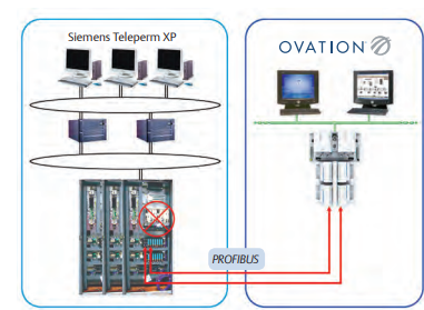

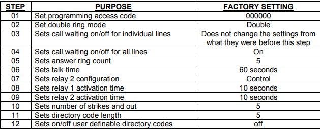

 Electrical Hazard: Only qualified personnel should perform installation procedures
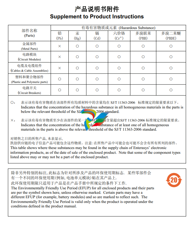
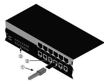


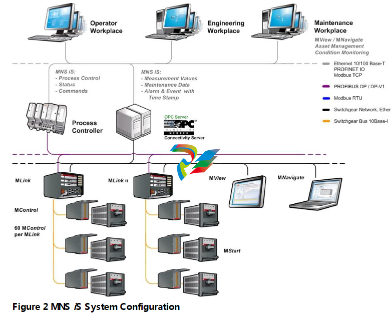 ## VII. Summary As the communication core of the MNS iS system, MLink enables efficient connection between internal devices and external control systems through hardware interfaces and software modules, supporting multiple industrial protocols and redundant configurations. Installation must strictly follow physical fixing and network configuration specifications. Faults can be quickly located through LED statuses to ensure stable system operation. In practice, relevant protocol manuals and MNavigate tool guides should be referenced to ensure correct parameter configuration.