schneiderUniversal Instruction Manual I/A Series® Pressure Transmitters Models IAP10, IAP20, IGP10, IGP20, IGP25 and IGP50, IDP10, IDP25, IDP50 Configuration, Calibration, Installation, and Operation
This Universal Instruction Manual is designed to provide the user with a single, concise, easy-touse manual that covers the key points needed for configuration, calibration, installation, and
operation of I/A Series Pressure Transmitters.
It covers all models of single variable pressure transmitters in the I/A Series family, including
absolute, gauge, and differential pressure transmitters, with FoxCom, HART, FOUNDATION
Fieldbus, or analog output electronics.
This universal manual, along with a DVD containing detailed information, is provided free of
charge with every I/A Series Pressure Transmitter, unless the purchaser requests that these two
items be omitted.
For additional detailed information about each model, including dimensional prints, parts lists,
and more detailed instructions, please refer to the standard DVD supplied or the optional paper
instruction book that is available for each model in the line.
♦ Standard Documentation Shipped with every I/A Series Pressure Transmitter
♦ A brief “Getting Started” Pocket-Sized Bulletin
♦ This Universal Instruction Manual
♦ A DVD that contains the complete documentation set for I/A Series Pressure
Transmitters
♦ When Optional Feature K1 is specified in the Model Code when the transmitter is
ordered:
A brief “Getting Started” Pocket-Sized Bulletin only is supplied
Optional Feature K1 is offered for those users who want to omit the documentation
shipped with every transmitter. This may be specified when multiple identical
transmitters are ordered and the user does not want multiple sets of documentation.
Electrical Certification Rating
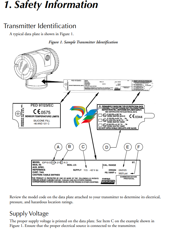
The electrical safety design code is printed on the data plate as part of the model code. See Item B
on the example shown in Figure 1. See the “Product Safety Specifications” section of the
instruction pertaining to your instrument on the enclosed DVD to identify this code. The type of
protection is also marked on the data plate. See Item D on the example shown in Figure 1.
PED Certification
The PED (Harmonized Pressure Equipment Directive for the European Community)
certification is offered only with transmitters ordered with ATEX Electrical Safety Design Code
selections. Transmitters with PED certification have a CE marking on the data plate that also
carries the PED number 0496.
Pressure Rating
The maximum working pressure (PS or MWP) for the transmitter is printed on the data plate.
See Item F on the example shown in Figure 1.
The data plate of flanged level transmitters and transmitters with flanged pressure seals are
stamped with the MWP if the transmitter pressure range is the limiting factor. It is stamped
“Flange Rate” if the flange rating is the limiting factor. The MWP of the flanged seal is stamped
on the seal data plate. See Figure 2.
Figure 2. Sample Seal Data Plate
When using transmitters with threaded, in-line saddle weld, or sanitary pressure seals, compare
the MWP of the transmitter on the transmitter data plate and the MWP of the seals on the seals
data plates and use the lesser value as the system MWP.
The MWP on the seal data plates may not be given at your process temperature. Use the
following information and industry standards as required to determine the actual pressure limits
for your application.
MODEL CODE: PSFPS-A2S0E313B MWP: 275 psig at 100°F
NOTICE: BREAKING CONNECTIONS VOIDS WARRANTY
BE SURE FILL FLUID CAN MIX SAFELY WITH PROCESS HIGH SIDE SEAL
HIGH SIDE FLUID, DC200, 10 cSt SILICONE TEMP RANGE -40 TO +450°F
PROCESS WETTED MATERIAL 316 SS
essure Seal PSFLT
Table 1. Pressure Seal PSFLT Pressure Limits
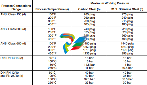
a. Flange temperature/pressure ratings only; seal temperature ratings may be lower; refer to Table 8
b. ASME/ANSI Material Group 1.1; linear interpolation acceptable
c. ASME/ANSI Material Group 2.2; linear interpolation acceptable
d. ANSI flanges per ASME/ANSI B16.5-1988.
e. DIN flanges per BS4504.
Pressure Seals PSFPS and PSFES
Table 2. Pressure Seal PSFPS and PSFES Pressure Limits
Pressure Seals PSSCR and PSSCT
The maximum working pressure of the seal process connection varies with the clamping device
used. Refer to Tri-Clover Tri-Clamp standards to determine the pressure limits of the clamping
system that you are using.
PSSSR and PSSST (Sanitary Tank Spud) Seals
The maximum working pressure of mini tank spud seal is 1.55 MPa at 120°C (225 psi at 250°F).
That of the standard tank spud seal is 1.38 MPa at 120°C (200 psi at 250°F).
Origin Code
The origin code identifies the area of manufacture and the year and week of manufacture. See
Item E on the example shown in Figure 1. In the example, 2A means the product was
manufactured in the Measurement and Instrument Division, 01 identifies the year of
manufacture as 2001, and 25, the week of manufacture in that year.
Operating Temperature Limits
The operating temperature limits of the electronics are -40°C and +85°C (-40°F and +185°F).
The limits are -40°C and +75°C (-40°F and +167°F) for IAP10, IGP10, IGP25, and IGP50
Transmitters with ATEX flameproof certification. Ensure that the transmitter is operated within
this range.
The sensor body operating temperature limits are determined by the sensor fill fluid. The cover
material, sensor diaphragm material and fill fluid are specified by two characters in the model
code on the data plate. See Item A on the example shown in Figure 1. Also see Table 5 and
Table 6 to interpret this part of the code and Table 7 to determine the sensor body temperature
limits. In the example IDP10-D12A21E-A3, the number 12 identifies the fill fluid in Table 5 as
silicone. Table 7 identifies silicone as having temperature limits of -46 and +121°C (-50 and
+250°F).
The diaphragm material code is found in the pressure seal model number which is located on the
pressure seal. See following example:
The housing material is 316 ss.
The gasket is provided by the user.
Pressure Seals PSSCT
The housing material is 316 ss.
The diaphragm material is 316L ss.
The gasket is provided by the user.
Pressure Seals PSSSR and PSSST
The housing material is 316 ss.
The diaphragm material is 316L ss.
The gasket material is EPDM.
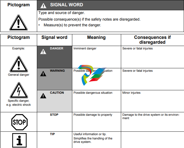
Warnings
General Warning
! WARNING
1. Transmitters must be installed to meet all applicable local installation regulations,
such as hazardous location requirements, electrical wiring codes, and mechanical
piping codes. Persons involved in the installation must be trained in these code
requirements to ensure that the installation takes maximum advantage of the safety
features designed into the transmitter.
2. A plug is supplied with each transmitter with 1/2 NPT conduit connection. It is
intended to provide moisture ingress protection of the unused housing conduit entry.
The plug must be wrench tight to achieve this level of protection. Thread sealant is
required. Explosion-proof applications may require a certified plug.
Housings with M20 / PG 13.5 threaded conduit connections are provided with an
ATEX certified plug. Thread sealant is required to provide moisture ingress
protection.
ATEX Warnings
! WARNING
Apparatus marked as Category 1 equipment and used in hazardous areas requiring
this category must be installed in such a way that, even in the event of rare incidents,
the versions with an aluminum alloy enclosure can not be an ignition source due to
impact and friction
Install ATEX certified transmitters in accordance with the requirements of standard
EN 60079-14.
! WARNING
To install a transmitter labeled with multiple approvals, select and permanently mark
the certification label in the tick block to distinguish the installed approval type from
the unused approval types. Once installed, the transmitter cannot be reinstalled using
any other approval type. Not following these instructions will jeopardize explosion
safety.
On IGPxx and IAPxx Transmitters with IECEx certification, the maximum constructional gap
(Ic) is less than that required by IEC 60079-1:2003 as detailed in the table below:
Explosionproof/Flameproof and Enclosure Warning
! WARNING
1. To prevent possible explosion and to maintain explosionproof/flameproof and dustignitionproof protection, plug unused openings with a certified metal pipe plug. For
1/2 NPT connections, both the plug and conduit must be engaged a minimum of five
full threads. For M20 and PG 13.5 connections, the certified plug provided and the
conduit must be engaged a minimum of seven full threads.
2. The threaded housing covers must be installed. Turn covers to seat O-ring into the
housing and then continue to hand tighten until the cover contacts the housing
metal-to-metal.
3. If the electronics housing is removed for any reason, it must be hand tightened
fully. Then engage the set screw until it bottoms out and back it off 1/8th turn. Fill
the set screw recess with red lacquer (Foxboro Part Number X0180GS or equivalent).
The housing then may be rotated up to one full turn in a counterclockwise direction
for optimum access to adjustments.
Intrinsically Safe and Type n Warning
! WARNING
Since live maintenance is not specified, to prevent ignition of flammable atmospheres,
disconnect power before servicing unless the area is certified to be nonhazardous.
Type n Warning
! WARNING
On transmitters certified for ATEX protection n, CSA Class I, Division 2, or FM
nonincendive for Class I, Division 2, the threaded housing covers must be installed.
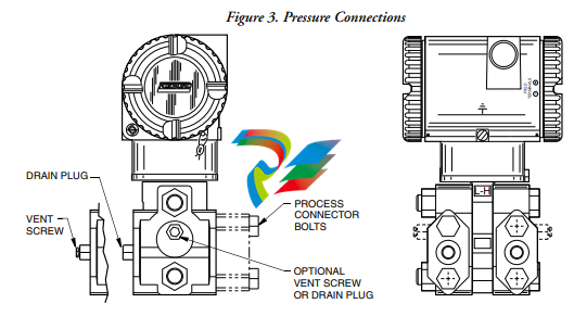
Pressure Warnings
! WARNING
When installing your transmitter, tighten process connector bolts to a torque of
61 N•m (45 ft•lb) and drain plugs and optional vent screws to 20 N•m (15 ft•lb). See
Figure 3.
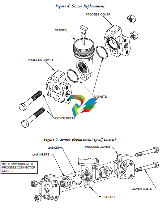
If a sensor is replaced or process covers are rotated for venting, replace the gaskets and
torque cover bolts (see Figures 4 and 5) to 100 N•m (75 ft•lb) in several even
increments. Torque values are 66 N•m (50 ft•lb) when optional 316 ss bolts are
specified (option B1). A pressure test is required. Perform a hydrostatic test with a
liquid following proper hydrostatic test procedures. Pressure test the process cover
assembly by applying a hydrostatic pressure of 150% of the maximum static and
overrange pressure rating to both sides of the process cover/sensor assembly
simultaneously through the process connections. Hold pressure for one minute. There
should be no leakage of the test fluid through the gaskets.
Process Fluid Warning
! WARNING
If process containing parts are to be disassembled:
1. Make sure that process fluid is not under pressure or at high temperature.
2. Take proper precautions concerning leakage or spillage of any toxic or otherwise
dangerous fluid. Follow any Material Safety Data Sheet (MSDS)
recommendations.
Seal or Sensor Fill Fluid Warning
! WARNING
Even though the volume of fill fluid is small, be sure that the fill fluid can mix safely
with the process fluid.
Parts Replacement Warning
! WARNING
This product contains components that have critical safety characteristics. Do not
substitute components. Replace components only with identical factory supplied
components. Component substitution may impair the electrical safety of this
equipment and its suitability for use in hazardous locations.
EU Declaration of Conformity
We, Manufacturer:
Invensys Systems, Inc.
38 Neponset Ave.
Foxboro, Massachusetts 02035
U.S.A.
declare under our sole responsibility that the
I/A Series Pressure Transmitters IGP, IAP, IDP, IPI, IMV
are in conformity with the protection requirements of Council Directives:
♦ 2004/108/EC on the approximation of the laws of the Member States relating to
Electromagnetic Compatibility
♦ 94/9/EC on the approximation of the laws of the Member States concerning
equipment and protective systems intended for use in potentially explosive
atmospheres
♦ 2014/68/EU on the approximation of the laws of the Member States concerning
pressure equipment
The basis on which Conformity is being declared:
♦ EN 61326-1:2006, Electrical equipment for measurement, control and laboratory use
EMC requirements, Class A emission limits, and immunity requirements according to
Table 2 for Industrial locations.
♦ EN50014 1997 A1 1999 A2 1999 Electrical apparatus for potentially explosive
atmospheres ‘General Requirements’.
♦ EN50018 2000 Electrical apparatus for potentially explosive atmospheres
‘Flameproof enclosures ‘d”.
♦ EN50020 1995 Electrical apparatus for potentially explosive atmospheres ‘Intrinsic
safety ‘I”.
♦ EN50021 1999 Electrical apparatus for potentially explosive atmospheres ‘Type of
protection ‘n”.
♦ EN50284 1999 Special requirements for construction, test and marking of electrical
apparatus of group II Category 1 G.
♦ EN 50281-1-1 1999 Electrical apparatus for use in the presence of combustible dust.
♦ EN 60079-15 2003 Electrical apparatus for explosive gas atmospheres – Part 15:
Electrical apparatus with type of protection “n”
For compliance with ATEX, products are in accordance with EC Type Examination Certificates
KEMA 00ATEX 1060X, KEMA 00ATEX 2019X and KEMA 00ATEX 1009X, issued by KEMA
Quality B.V., Ultrechtseweg 310, 6812 AR Arnhem, The Netherlands, Notified Body number
0344, and with EC Type Examination Certificates SIRA 04ATEX1349, SIRA 04ATEX2335X,
SIRA 06ATEX4056X, SIRA 06ATEX2055X, and SIRA 06ATEX4019X, issued by Sira
Certification Service, Rake Lane, Eccleston, Chester, CH4 9JN, England, Notified Body number
0518. The authorized markings for each certificate are shown below. The actual ATEX markings
on the product vary according to model code. Refer to Product Specification Sheet and marking
on product for details pertaining to individual model codes.
KEMA 00ATEX1060X II 3 G EEx nL IIC T4 … T6
II 1 GD EEx nL IIC T4 … T6 T 135°C
KEMA 00ATEX1009X II 1 G EEx ia IIC T4 … T6
II 1/2 G EEx ib IIC T4 … T6
II 1 GD EEx ia IIC T4 … T6 T 135°C
II 1/2 GD EEx ib IIC T4 … T6 T 135°C
KEMA 00ATEX2019X II 2 G EEx d IIC T6
II 2 GD EEx d IIC T6 T 85°C
SIRA 04ATEX1349 II 2 GD EEx d IIC T6 T 85°C
SIRA 04ATEX2335X II 1G EEx ia IIC T4
SIRA 06ATEX4056X II 3 GD EEx nL IIC T4
SIRA 06ATEX2055X II 1 GD EEx ia IIC T4
SIRA 06ATEX4019X II 3 G EEx nL IIC T4
For the Pressure Equipment Directive, conformity is based on a certificate issued by DNV GL,
Veritasveien 1, 1322 HOVIK, Norway, Notified Body number 0496, based on Maximum
Working Pressure (MWP). Conformity Assessment Module “H” is applied for Models IGP, IAP,
IMV and IDP where the MWP is greater than 200 bar. The applicable design standard is
IEC/EN 61010-1
. Installation
! CAUTION
To avoid damage to the transmitter sensor, do not use any impact devices, such as an
impact wrench or stamping device, on the transmitter.
NOTE
1. The transmitter should be mounted so that any moisture condensing or draining
into the field wiring compartment can exit through one of the two threaded
conduit connections.
2. Use a suitable thread sealant on all connections.
3. If the transmitter is not installed in the vertical position, readjust zero output to
eliminate the position zero effect.
Mechanical Installation
Differential Pressure Transmitter
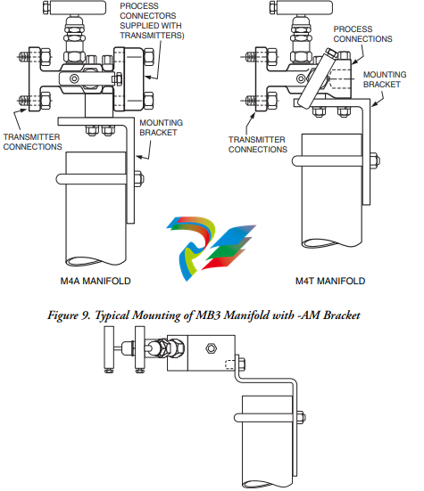
The IDP10, IDP25, and IDP50 differential pressure transmitters can be supported by the process
piping (Figure 6), on a bypass manifold (Figures 7 through 10), or mounted to a vertical or
horizontal pipe or surface using an optional mounting bracket (Figures 11 through 16). For
dimensional information, refer to DP 020-446.
NOTE
1. The IDP25 and IDP50 transmitters are only available in the Traditional Structure
at this time.
2. If the transmitter is not installed in the vertical position, readjust zero output to
eliminate the position zero effect.
3. When pvdf inserts (structure codes 78/79) are used, the process connection must
be made directly to the pvdf inserts in the Hi and Lo side process covers.
4. The transmitter should be mounted so that any moisture condensing or draining
into the field wiring compartment can exit through one of the two threaded
conduit connections.
Process-Mounted Transmitter
Figure 6 shows the transmitter mounted to and supported by the process piping
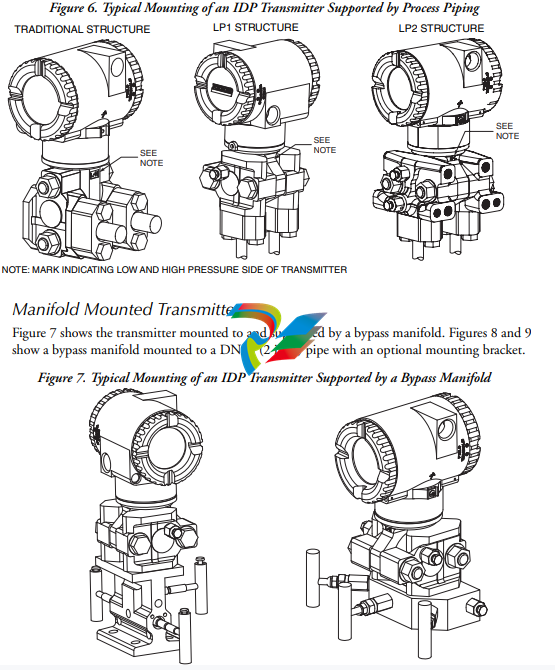
Figure 8. Typical Mounting of M4A and M4T Manifold with -AM Bracket
Pipe- or Surface-Mounted Transmitter
To mount the transmitter to a pipe or surface, use the Standard Mounting Bracket Set (Model
Code Option -M1 or -M2) or Universal Bracket Mounting Set (Model Code Option -M3).
Standard Mounting Bracket
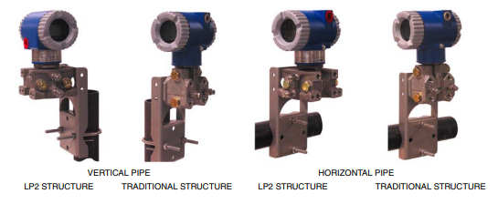
The transmitter (with either traditional or LP2 low-profile structures) can be mounted to a
vertical or horizontal, DN 50 or 2-in pipe using a standard bracket. See Figure 11 for details and
Figure 12 for examples of different situations. Secure the mounting bracket to the transmitter
using the four screws provided. Mount the bracket to the pipe. To mount to a horizontal pipe,
turn the U-bolt 90° from the position shown in Figure 11. The mounting bracket can also be
used for wall mounting by securing the bracket to a wall using the U-bolt mounting holes.
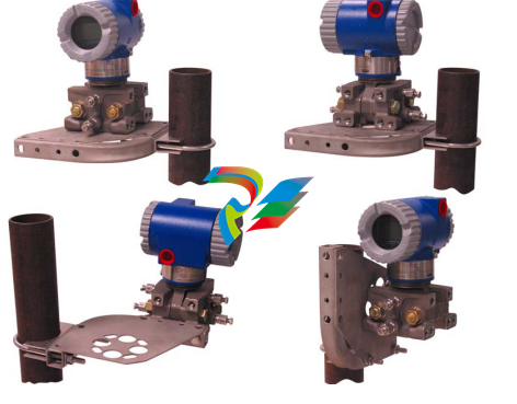
Universal Mounting Bracket
The transmitter (with either traditional or LP2 low-profile structure) can be mounted in a myriad
of positions to a vertical or horizontal, DN 50 or 2-in pipe using a universal bracket. See
Figure 13 for details of a universal bracket and Figure 14 through Figure 16 for examples of
different mounting situations. Secure the mounting bracket to the transmitter using the two long
or four short screws provided. Mount the bracket to the pipe. The mounting bracket can also be
used for wall mounting by securing the bracket to a wall using the U-bolt mounting holes.
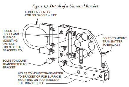
Figure 14. Mounting a Transmitter with Traditional Structure Using a Universal Bracket
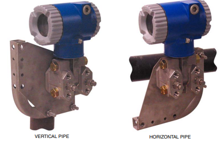
Figure 15. Vertical Pipe Mounting a Transmitter with LP2 Structure Using a Universal Bracket