There are different automation systems to control processes in industry. One of them is
DeltaV, which is a product from Emerson Process Management. Recently, Sandvik
Coromant, bought the DeltaV automation system for using it in production. To increase
the knowledge about DeltaV at Sandvik Coromant a project was initiated with the aim to
create a test platform and a course compendium for self learning. This thesis describes
how the test platform was developed and its functionality
Testplattform för styrsystemet DeltaV
Examensarbete vid Skolan för Elektro- och Systemteknik
Sammanfattning
För att styra processer i industrin finns det olika styrsystem. Ett av dessa är DeltaV, som
är en produkt från Emerson Process Management. Nyligen köpte Sandvik Coromant
styrsystemet DeltaV för att använda det i sin produktion. För att öka kunskapen om
DeltaV på Sandvik Coromant initierades ett projekt: Att utforma en test plattform och ett
kurskompendium för självlärning. Denna uppsats beskriver hur tesplattformen har
utvecklats och dess funktionalitet.
Foreword
This report presents a Master’s project at the School of Electrical Engineering at the
Royal Institute of Technology (KTH) in Stockholm, Sweden.
The project has been performed at Sandvik Coromant in Västberga, Sweden. I want to
thank Sandvik Coromant for accepting me and Stefan Hedberg and Patrik Schütt for
their support throughout the project. I would also like to thank my supervisor, Professor
Håkan Hjalmarsson, at the School of Electrical Engineering, KTH, for his support.
I have performed this project in collaboration with Daniel Engdahl, who also is a member
of this project
Chapter 1
Introduction
Sandvik Coromant is the world’s leading manufacturer of cutting tools for the
metalworking industry. Advanced production processes require advanced automation
systems for the control.
Production processes normally consist of a number of devices like valves, engines,
sensors, transmitters and controllers. These devices are controlled and monitored from
an automation system.
Sandvik Coromant has recently bought a new automation system, DeltaV, which is a
product from Emerson Process Management. To increase the knowledge about the
automation system at Sandvik Coromant, a project was initiated with the aim to create a
test platform and a course compendium for self learning.
This chapter describes the problem to be solved, the background to the automation
system DeltaV and gives the outline for the rest of the report.
1.1 Problem
In the following subsections the problem is described.
1.1.1 Task
The task in this project was to create a portable test platform for an educational purpose
for one of the automation systems, DeltaV from Emerson Process Management, that is
used at Sandvik Coromant. Along with the test platform, there should also be a course
compendium that describes how to learn DeltaV by using the test platform. The test
platform and the course compendium should together work as selflearning tools for the
personell at Sandvik Coromant. The platform should be small enough to be portable, so
that it can be brought to people who needs to learn DeltaV, independently of where they
are stationed.
Since the purpose of the task was not to learn how the production processes work, there
was not any requirement that the test platform should be similar to any process where
DeltaV is used at Sandvik Coromant. The only required similarity between the test
platform and the production processes at Sandvik Coromant was supposed to be that
similar measurement equipment was used.
1.1.2 Purpose
The DeltaV automation system has been used at Sandvik Coromant for two years. The
purpose of creating a test platform was to increase the knowledge of the automation
system among the personnel.
Since production processes are in general very costly to interrupt, a test platform was
needed to experiment with the functions of DeltaV. With the test platform the personnel
at Sandvik Coromant should be able to learn more about the automation system on their
own by testing how to control a physical process. The test platform along with the course
compendium should work as a selflearning tool.
1.1.3 Previous work
This is the first test platform and also the first course for DeltaV that has been developed
at Sandvik Coromant. The manufacturer of DeltaV, Emerson Process Management,
provides DeltaV courses. However, these courses do not come with a portable test
platform.
1.1.4 Description of the problem
The desire from Sandvik Coromant was to have a physical process, a software with
control algorithms for controlling the physical process and a course compendium on how
to learn DeltaV.
The requirement on the hardware in the physical process was that it should at least
include basically the same equipment as the production processes that are controlled
with DeltaV; relays, fuses, pressure transmitter, proximity sensors etc. Naturally, the
hardware should also include the automation system, DeltaV. The platform should be
small enough to be portable.
The requirement on the software part was similarly that it should at least include some
similar algorithms as the software for the real production processes includes. It was also
required that the software should include an operator interface in which an operator can
get the relevant information about the process; alarms indicating that something is
wrong, diagrams, an illustration of the process where the operator can follow what
happens etc.
The requirement on the course compendium was that a person who reads it should be
able to replicate the control software that was developed in this project. Persons taking
the course will have the original software as a key, which they should only use if they
experience significant problems.
Hence, to meet all requirement from Sandvik Coromant, the finished platform and
additional educational material should include the following:
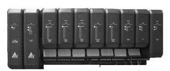
• The DeltaV System with controller cards, I/O cards and fieldbus cards.
• Devices that are more or less the same as in the production processes at
Sandvik Coromant where DeltaV is used, for instance proximity sensors or
pressure transmitters.
• A software control system containing similar algorithms as the production
processes at Sandvik Coromant, for instance it might be of great relevance to
use a PID controller.
• An operator interface illustration that follows the physical process. The operator
environment should also contain an alarm list.
• A course compendium with both general information about functions in DeltaV
and instructions on how to create the same control system as the one which was
developed in this project.
1.1.5 Aim
The aim of this project was to make a test platform along with a course compendium.
The test platform should be portable so that it can be brought to people for education in
DeltaV regardless of where the persons are stationed. This education should give a
general knowledge on how to use DeltaV and after completing this course the engineers
should be able to implement simple control systems.
1.2 DeltaV-a DCS automation system
In industry there are different automation systems; some that are more basic and some
that are more advanced. This section will give an introduction to automation systems in
general and the specific automation system, DeltaV, that this project concerns. Figure
1.1 shows the hardware of the DeltaV automation system.
DeltaV is a DCS automation system. DCS is short for Distributed Control System and it
is and automation system that has evolved from PLC.[1]
PLC is short for Programmable Logic Controller. Originally PLC systems replaced old
automation systems that included many relays. PLC systems did then include only
discrete signals and when DCS was new, the difference between the two automation
systems was that DCS also included analog signals. However, today PLC includes both
analog and discrete signals and the difference between PLC and DCS is vague. Newer
designs look similar both in hardware and in software.[2]
The DeltaV automation system consists of one hardware part and one software part. In
the following subsections both parts willl be explained.
1.2.1 Controller, I/O and fieldbus cards
The hardware consists of controller cards, I/O cards and fieldbus cards.
In the controller a CPU is located and it is in the controller that the program containg
information on how to control the process is stored. This program is downloaded to the
controller from a workstation. The I/O cards and the fieldbus cards are capable of
sending or/and receiving signals to and from the devices. Hence, the I/O cards and
fieldbus cards send the signals that they get from the devices to the controller and the
signals that they get from the controller to the devices. The controller also sends
information to an operator interface, so that the operator of the process can monitor it.
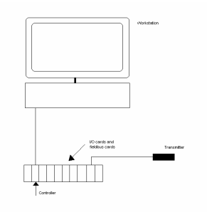
Figure 1.2 shows an overview of the connections for an automation system.
Figure 1.2. Overview of the connections for an automation system. A device is connected to an I/O card
or a fieldbus card. The controller communicates with the I/O cards and the fieldbus cards and is connected
to a workstation. The program is downloaded from a workstation to the controller.
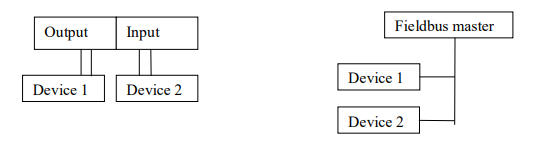
Figure 1.3. The network is reduced when using a fieldbus. Fieldbus cards allow communication in both
directions and the wiring is much less when using fieldbus cards.
In this project three fieldbus cards are used; Foundation Fieldbus, Profibus and ASInterface. Foundation Fieldbus and Profibus handle analogue signals and AS-i only
handles discrete signals.
The communication technology for all three fieldbus cards follows a standard model
called OSI (Open Systems Interconnection). An OSI model divides the functions of a
protocol into several layers. Each layer uses only the functions of the next layer, and
only exports functionality to the preceding layer. The main feature of the OSI-model is in
the interface between layers which dictates the specifications on how one layer interacts
with another. This enables that a layer written by one manufacturer can operate with a
layer from another. The OSI model contains seven layers, but the fieldbus model is only
based on three major layers (layers 1,2 and 7 in the OSI-model). [3]
AS-Interface (AS-i)
AS-i is the most simple fieldbus. It is designed for connecting binary devices.
The OSI-model consists of three layers; Transmission Control, Execution Control and
Application Layer Interface.
The Transmission Control includes the wiring of the field devices and other components
in the process. This layer receives messages and encodes them to physical signals.
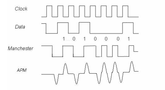
The signals which are in NRZ code (non-return-to-zero code) are encoded using
Manchester II coding and then implemented with APM coding.
The principle of Manchester encoding is that every bit period has one transition in the
middle of the period. A positive transition represents a logic one and a negative
transition represents a logic zero. Transitions that are not in the middle of the bit period
do not carry any useful information. These transitions only have the purpose to set the
signal in the state where the mid-bit transition can take place.
With APM, pulses are created; a positive pulse is created at a low to high edge and a
negative pulse is created at a high to low edge. In figure 1.4 the coding principle for both
manchester encoding and APM is shown. [4][5]
Figure 1.4. Illustration of the principle for the Manchester encoding and APM encoding. The data is coded
to Manchester code so that a transition occurs in the middle of every bit period. A positive transition
represents a logic one and a negative transition represents a logic zero. Transitions that are not in the
middle of the bit period do not carry any useful information. These transitions only have the purpose to set
the signal in the state where the mid-bit transition can take place.
The Execution Control is of Master/Slave characteristic. The AS-i card works as the
network master. The master automatically controls all communication over the AS-i
cable. The master interrogates all the available AS-i addresses and repeats the process.
The Application Layer Interface makes it possible to download the DI and DO functions
to the controller. This enables communication between the controller and the devices. [6]
Foundation Fieldbus
The Foundation Fieldbus card used in this project is H1. As compared to another
foundation fieldbus card H2, the H1 network is a lower speed and lower cost network
than H2.
The communication for foundation fieldbus follows the OSI model with three layers;
Physical Layer, Communication Stack and User Application.
The Physical Layer includes the wiring of the field devices and other components in the
process. This layer gets encoded messages from the next layers and converts them into
physical signals. The signals are encoded using the Manchester Biphase-L technique.
In manchester Biphase-L code a positive transition in the middle of a bit period
represents a logic zero and a negative transition in the middle of a bit period represents
a logic one, see figure 1.5.
Figure 1.5. Encoding with Manchester Biphase-L technique. In manchester Biphase-L code a positive
transition in the middle of a bit period represents a logic zero and a negative transition n the middle of a bit
period represents a logic one [5]
The Communication Stack is the layer that manages communication between a device
and a host or the communication between two devices.
In foundation fieldbus communication with H1, the H1 card works as a Link Active
Scheduler (LAS). A LAS is a deterministic, centralized bus scheduler that maintains a list
of transmission times for all the data buffers in all the devices that need to transmit in
cyclical fashion. [7] Field devices may also have Link Master capabilities and would in
the case that the H1 card fails, work as LAS. The H1 card is the only primary Link
Master allowed on the fieldbus segment. No other Link Master is allowed on the
segment or unpredictable results can occur. DeltaV supports one backup Link Master
device on each fieldbus segment.[8]
The communication between LAS and publishers and subscribers can be scheduled or
unscheduled.
Scheduled communication-The LAS maintains a list of transmit times for all data buffers
in all connected devices. When it is time for a device to transmit its data, the LAS sends
a CD (Compel Data) to that device. The device publishes (sends) data to all devices on
the fieldbus. The devices which are configured to receive the data are called
subscribers.
Unscheduled communication- These transmissions are done with PN (Probe Node) or
PT (Pass Token) and take place between transmissions of scheduled messages. The
LAS sends a PN (Probe Node) message to see whether any device changes have been
made. The changes are added to a live list. It is possible for a device to transmit
unscheduled messages after it has received a PT (Pass Token) from the LAS.
The User Application is a standard user application defined by Fieldbus Foundation.
This layer is not defined by the OSI-model. [9]
Profibus
The Profibus that is used in the test platform is Profibus DP (Decentralized Periphery).
Profibus DP is the most common Profibus.
The OSI-model for Profibus communication consists of three layers;
The Physical Layer defines the physical transmission characteristics. The signals are
sent using UART (Universal Asynchronous Receiver/Transmitter). With UART, data are
transmitted as streams of characters. Every character starts with a start bit (a 0) and
ends with a stop bit (a 1). The start bit allows the receiver to recoginize the start of a
new character and the stop bit makes sure that there will be a transition at the start of
the stop bit. [10]
The Communication Stack is a communication layer which defines the Bus Access
Protocoll. In a Profibus DP system the communication type is master/slave and both
multi-master and mono-master systems are possible. The protocoll used is Media Acces
Control (MAC), which specifies the procedure when a station is permitted to transmit
data on the bus. The MAC must ensure that only one station has the right to transmit
data at a time.
Hence, the requirements on the MAC protocol are that the following should be
accomplished:
• During communication between master stations it must be ensured that each of
these masters gets sufficient time to execute its communication tasks within a
precisely defined time interval.
• Cyclic, real time data transmission is to be implemented as fast and as simple as
possible for communication between a master and its slaves. [11]
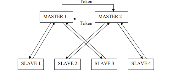
The multi-master system manages communication by having a token that is sent
between the masters. When a master has the token, it can communicate with its slaves,
see figure 1.6. [12]
Figure 1.6. The multi-master communication of Profibus. The multi-master system manages
communication by having a token that is sent between the masters. When a master has the token, it can
communicate with the slaves.
The User Layer is defined as a standard user layer. [13]
1.2.2 Description of the Software tools in DeltaV
The automation system has many different software applications. For this process the
applications that have been used are: A tool for organizing the database, a tool for
creating control modules and an animation tool for creating operator interfaces.
The Database
A database contains controllers, I/O and fieldbus cards in the system and control
modules.
The Control Modules
In DeltaV the control of the system can be organized in control modules. A control
module can be very simple and contain only one or two input parameters. It can also be
more complex with for instance PID-control.
There are several types of control modules. Which one is used depends on its purpose.
The most important control modules are;
• Function Block Diagrams (FBD)
An FBD is always necessary to be able to send signals from the computer to the
process or get signals from the process to the computer. An FBD consists of, as
the name tells us, function blocks. A function block can be an input block, for
instance it can contain a signal from a temperature transmitter. If this signal value
should be shown on the operator interface, there must be a reference from the
module containing this block to the operator interface. For each signal, only one
input/output block can be used. It is possible to get the signal at another place, for
instance in a different control module, by referring to it. Other function blocks are,
for instance, multipliers and PID blocks.
• Sequential Function Charts (SFC)
An SFC is a control module for determining the sequence of execution. A SFC
consists of a bipartite graph (two states are always separated by a transition). In a
State, actions can be permormed. This means that parameter values can be set,
for instance a light connected to a relay that gets a signal from the automation
system can be switched on. Transitions contains the conditions that need to be
fulfilled for the process to change states. In an SFC references are made to the
FBDs. For instance, if it is desired to have a transition when the pressure is above
1200 mbar, there must be a reference to the input block in the specific FBD that
gets an input from the pressure transmitter.
The Operator Interface
The tool for creating an operator interface is object based. It contains images of valves,
engines, fire etc. The objects can be animated which makes it possible to create an
operator environment in which the operator can easily get an impression of the state of
the process.
1.3 Report Outline
This report is arranged as follows:
Chapter 2 – The platform and the course material presents how the hardware as well as
the software for the test platform have been developed.
Chapter 3 – Results presents the result, i.e. the finished test platform.
Chapter 4 – Conclusions presents the conclusions of this project. The chapter also
presents a few suggestions on how the test platform can be improved.
Chapter 2
The platform and the course material
The following chapter will present the platform and the system design; firstly the devices
that are present and how the physical process works and secondly the course material.
2.1 The system design
When choosing the system design the requirements presented in Section 1.2.4 were
first
and foremost taken into account. When considering the purpose of the test platform an
addition was made to the requirements:
• To make a process that is easy to understand, but that is adequately advanced
for using advanced control tools in DeltaV.
With these requirements a system design was developed. The principle of the process is
briefly described below. Figure 2.1 illustrates of the principle of the process.
A pressure tank with a needle valve is filled half way up with water. When the control
system starts, air flows into a tank through a mass flow controller and the pressure in the
tank is controlled to stabilize around ~1500 mbar.
When the pressure has been held around 1500 mbar for a specified time a pneumatic
valve will open and tap out water into an open tank that is placed below the pressure
tank. The valve will stay open until a level sensor indicates that the tank is full.
When the open tank is full a heating plate will start to heat up the water. The
temperature is controlled with on/off controlling to ~35 ºC.
To continue the process the open tank has to be removed, emptied and put back in
place. This will restart the process. This can be repeated until the pressure tank is
empty.
• Buttons
The button device consists of one red button with red light and one green button
with green light. The buttons can also be lit.
Devices connected to Foundation Fieldbus
• Pressure transmitter
A pressure transmitter measures and transmits the pressure value.
• Temperature transmitter
A temperature transmitter measures and transmits the temperature.
Devices connected to Profibus
• Mass Flow Controller
A mass flow controller controls the inflow of gas from one place to another.
Devices connected to Discrete Out
• Relays
A relay is a device that can control other devices with on and off.
Devices connected to relays
Light bulb
Heat plate
• Valve Island
A Valve Island is a device with several electrically controlled valves. The valves
are normally closed, but they open when they receive a signal from the controller.
Devices connected to Discrete In
• Capacitive Proximity Sensor (Level Transmitter)
A capacitive proximity sensor is used for detecting objects that are proximal to the
sensor.
Other objects in the test platform
• Pressure tank
A pressure tank was constructed for the test platform. It is designed to be able to
handle a pressure of 10 bar and to contain both water and air. It has four
connections; one that can be connected to the mass flow controller, one that can
be connected to the pressure transmitter, one that can be connected to the
needle valve and one that can be connected to a pneumatic valve. It also has one
inflow so that it can be filled with water.
• Open tank
The open tank is a much less advanced tank than the pressure tank. It is open
and therefore it must not be able to handle any pressure and it does not have any
connections. It is metallic so that it can be detected by an inductive proximity
sensor.
• Pneumatic Valve
A pneumatic valve is normally closed, but opens if it is exposed to pressurized air.
• Compressor / Pressurized air media
Depending on where the platform is used a compressor or pressurized air media
is used. A compressor is used when there is no pressurized air media available.
Since a compressor has a high sound level and in addition is heavy to carry it is
only meant to be used when there is no other option.
Detailed description of the Physical Process
1. DeltaV controller, I/O and
fieldbus cards
2. Pressure transmitter
3. Mass Flow Controller
4. Valve island
5. Inductive Proximity Sensor
6. Capacitive Proximity Sensor
7. Temperature Transmitter
8. Push buttons
9. Relays
10. Heat plate
11. Light bulb
12. Pressure tank
13. Needle valve
14. Pneumatic valve
15. Open tank
As mentioned the physical process is a process with no actual purpose. The only
purpose is to have a physical process to follow while learning how to use DeltaV. In the
previous subsection all devices and other things in the physical process were described.
This section will instead focus on how the devices are used to create a functional
automated process.
Figure 2.2 illlustrates how the objects in the process are connected.
Before starting the process, the pressure tank is partly filled with water and the open
tank is empty. On the button device the red light is on. A compressor that is not included
in the control should be switched on by the operator. (The compressor could as
mentioned above be exchanged with pressurized air media). The compressor exposes
the valve island with pressurized air.
The process is started by pressing a green button. This button exists both in the
operator interface and physically on the test platform. When the button is pressed the
green light on the button device will be switched on and the red light which indicates that
the process is off will be switched off. The valve island will open the valve that is
connected to the mass flow controller. The Mass Flow Controller will then be exposed to
pressurized air.
The mass flow controller will control the pressure in the pressure tank so that it stabilizes
at approximately 1500 bar. The control is done with the software with PID control. How
the PID parameters are set, is described in the Subsection 2.2.2.1.
When the pressure in the pressure tank has been between 1400 mbar and 1600 mbar
for one minute, the inductive sensor signals that the open tank is in its place below the
pressure tank and the capacitive signals that it is not already filled with water, the valve
island will open the valve that is connected to the pneumatic valve. When the pneumatic
valve is exposed to the pressurized air from the valve island, it will open and water will
flow out from the pressure tank.
The valve on the valve island that is connected to the pneumatic valve will be open until
the capacitive sensor indicates that the water level is high. The pneumatic valve will
close when it does no longer get pressurized air from the valve on the valve island.
If the water temperature is less than 35 C, the heat plate starts heating. The heater will
only start if there is a tank filled with water on it.
When the water temperature has reached 35 C, the heating will stop. For the process
to go on, the open tank has to be removed, and put back. This will bring the process
back to the state when the pressure in the tank is controlled to be between 1400 and
1600 mbar. From that state it will continue and the process can go on until the pressure
tank is empty.
If the open tank would not have been emptied when the water temperature was higher
than 35 C, the heating would have started all over again when the temperature is below
35 C. The heating will always start when the open tank is in place and filled with cold
water, unless the red button (the emergency button) has been pressed.
The red button can be pressed at any time in the process and the process will enter its
standby state. In the stand by state everything is off except for the red light on the button
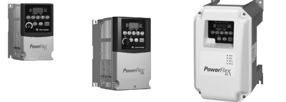
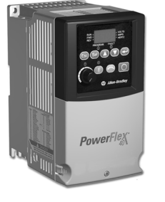
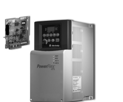
The PowerFlex® 700 AC drive offers outstanding performance in an easy-to-use drive that you have come to
expect from Rockwell Automation. The PowerFlex 700 AC drive is designed to control three-phase induction
motors in applications with requirements ranging from the simplest speed control to the most demanding
torque control. The drive has volts per hertz, sensorless vector, and vector control. Vector control includes
Allen-Bradley’s patented Force Technology, which provides world class motor control.
Flexible Packaging and Mounting
• IP20, NEMA / UL Type 1 – For conventional mounting inside or outside a control cabinet. Conduit plate is removable for easy
installation and replacement without disturbing conduit.
• IP54, NEMA / UL Type 12 – standalone, wall mount drives are available for dust-tight applications with power ratings 75…200 Hp
(Frames 5 and 6).
• IP54, NEMA / UL Type 12 – Flange mount drives with an IP00, NEMA / UL Type Open front. These can be installed in a user supplied
cabinet to meet IP54, NEMA / UL Type 12. This allows most heat to be exhausted out the back of the cabinet while keeping the cabinet
protected. Power ratings range 75…200 Hp (Frames 5…6).
• Zero-Stacking™ Drive– Frame 0…6 drives can be mounted next to each other with no reduction of surrounding air temperature rating 50 °C (122 °F). This unique bookshelf design also allows access to one drive without disturbing another.
• Conformal Coating – The drive is coated in an insulator, or non-conducting substance, that helps protect it from moisture, fungus,
dust, corrosion, abrasion, and other environmental stresses caused by highly polluted atmospheres. The coating improves product
lifetime expectancy when exposure to corrosive environment is present. It helps maintain long-term surface insulation resistance,
ensuring operational integrity of the assembly.
Space Saving Hardware Features
• Integral EMC Filtering plus built-in DC bus choke common mode cores and common mode capacitors provides a compact, all-in-one
package solution for meeting EMC requirements. Frames 0…6 only.
• Internal Communications allows you to integrate the drive into the manufacturing process. Status indicators for all internal
communication options are visible on the cover for easy setup and monitoring of drive communications. You can easily manage
information from shop floor to top floor and seamlessly integrate their complete system as they control, configure, and collect data.
• Integral Dynamic Brake Transistor delivers a cost-effective means of switching regenerative energy without costly external
chopper circuits. These internal transistors are available in power ratings 0.5…200 Hp.
• Internal Dynamic Brake Resistor (up to 25 Hp) requires no extra panel space, and supplies a large amount of braking torque for
short periods.
Easy to Use Human Interface Tools
The PowerFlex 7-Class AC drives provide common Human Interface tools that are familiar and easy to use. These include the LCD Human
Interface modules and PC-based configuration tools.
Human Interface Module
The LCD Human Interface modules provide:
• Large and easy to read 7 line x 21 character backlit display
• Variety of languages (English, French, German, Italian, Spanish, Portuguese, Dutch)
• Alternate function keys for shortcuts to common tasks
• “Calculator-like” number pad for fast and easy data entry (Full Numeric version only)
• Control keys for local start, stop, speed, and direction
• Remote versions for panel mount application
Connected Components Workbench Software
Connected Components Workbench™ programming and configuration software leverage proven Rockwell Automation and Microsoft® Visual
Studio® technologies for fast and easy drive configuration, controller programming, and integration with the HMI editor.
Multiple motor control algorithms allow performance that is matched to the application need:
• Volts/Hertz for simple Fan and Pump applications.
• Sensorless Vector for high torque production over a wide speed range.
• Vector for outstanding torque regulation and excellent low speed/zero speed
performance (w/Vector Control cassette).
The PowerFlex 700 drive’s Vector Control uses Allen-Bradley’s patented Force Technology
which provides excellent low-speed performance – whether it is operated with or without
feedback. While this industry-leading control provides the highest level of drive performance,
it is as easy to use as any general-purpose drive available.
Drives Features
• Fast-acting Current Limit and Bus Voltage Regulation result in maximum accel/decel without tripping.
• High-speed analog inputs improve drive response to torque or speed commands.
• Programming flexibility allows parameters to be linked within the drive.
• Flying Start delivers smooth and instantaneous connection into rotating loads, regardless of commanded direction, without the need
for any speed feedback.
• Integral Process PI Control can eliminate the need for a separate process loop controller.
• Inertia Ride-Through offers tripless operation during a prolonged power outage by using the rotating energy that is stored in high
inertia, low-friction loads.
• Position Indexer/Speed Profiler uses a 16-step indexer to provide point-to-point positioning or velocity profiling based on encoder
counts, digital inputs, parameter levels, or time.
• TorqProve™ assures control of the load when transferring control between the drive and a mechanical brake.
• Speed Regulation – Open Loop or Closed Loop
– Slip Compensation delivers a minimum 0.5% speed regulation without feedback hardware.
– Droop allows drives to load share without fighting each other.
– Encoder Feedback provides up to 0.001% speed regulation for the tightest application requirements.
• Torque Regulation – Open Loop or Closed Loop
– Open Loop torque regulation provides 5% regulation.
– Encoder Feedback provides 2% regulation and the ability to hold full load at zero speed.
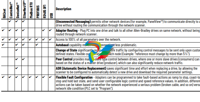
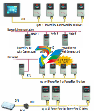
Unsurpassed Capability in Network Communications
PowerFlex drives are fully compatible with the wide variety of Allen-Bradley DPI™ communication adapters, offering the following benefits:
Drive, Fuse, and Circuit Breaker Ratings
The PowerFlex 700 can be installed with input fuses or an input circuit breaker. National and local industrial safety regulations and/or
electrical codes can determine additional requirements for these installations.
The tables on the following pages provide recommended AC line input fuse and circuit breaker information. See Fusing and Circuit Breakers
below for UL and IEC requirements. Sizes that are listed are the recommended sizes based on 40 °C (104 °F) and the U.S. NEC. Other country,
state, or local codes can require different ratings. Tables with DC link fuse recommendations for DC input drives are also provided.
Fusing
The recommended fuse types are listed below. If available current ratings do not match those listed in the tables that are provided, choose
the next higher fuse rating.
• IEC – BS88 (British Standard) Parts 1 and 2, EN60269-1, Parts 1 and 2(1), type gG or equivalent must be used.
• UL – UL Class CC, T, RK1, or J must be used for Frames 0…6.
Circuit Breakers
The “non-fuse” listings in the following tables include inverse time circuit breakers, instantaneous trip circuit breakers (motor circuit
protectors) and 140M Motor Protection Circuit Breakers (MPCBs) that are rated for use as self-protected combination motor controller
(Frames 0…6 only). If one of these is chosen as the desired protection method, the following requirements apply:
• IEC – Both types of circuit breakers and 140M self-protected combination motor controllers (Frames 0…6 only) are acceptable for IEC
installations.
• UL – Only inverse time circuit breakers and the specified 140M self-protected combination motor controllers (Frames 0…6 only) are
acceptable for UL installations.
Circuit Breaker – inverse time breaker. For US NEC, minimum size is 125% of motor FLA. Ratings that are shown are maximum.
(5) Motor Circuit Protector – instantaneous trip circuit breaker. For US NEC, minimum size is 125% of motor FLA. Ratings that are shown are maximum.
(6) Bulletin 140M devices with adjustable current range must have the current trip set to the minimum range that the device does not trip.
(7) Manual Self-Protected (Type E) Combination Motor Controller, UL Listed for 208V Wye or Delta, 240V Wye or Delta, 480Y/277V or 600Y/347V. Not UL Listed for use on 480V or 600V Delta/
Delta, corner ground, or high-resistance ground systems.
(8) The A1C ratings of the Bulletin 140M devices can vary. See publication 140-TD005 or 140M-TD002.
(9) Maximum allowable rating by US NEC. Exact size must be chosen for each installation.
(10) UL Type 12/IP54 (flange mount) heat sink ambient temperature rating is 40° C/ambient of unprotected drive portion (inside enclosure) is 55° C. The ambient temperature for the UL Type 12/
IP54 standalone drives is 40° C.
(11) Must remove top label and vent plate, drive enclosure rating is IP00, NEMA / UL Type Open.
(12) Frames 0…4 temperature rating is for NEMA / UL Type Open. The adhesive top label must be removed to operate drive at this temperature. Frames 5 and 6 do not have a top label.
(13) Drives have dual current ratings; one for normal duty applications, and one for heavy-duty applications. The drive can be operated at either rating.
(14) Note: 600V class drives below 77 amps (Frames 0…4) are declared to meet the Low Voltage Directive and UK Low Voltage Regulations. It is the responsibility of the user to determine
compliance to the EMC Directive and UK EMC Regulations.
(15) When using a Manual Self-Protected (Type E) Combination Motor Controller, the drive must be installed in a ventilated or non-ventilated enclosure with the minimum volume that is specified
in this column. Application-specific thermal considerations can require a larger enclosure.
(16) Temperature rating is for IP20, NEMA / UL Type 1. For IP00, NEMA Type Open the temperature rating is 65 °C for the control board and 40 °C for the heat sink entry air.
(17) 40 °C = 104 °F; 45 °C = 113 °F; 50 °C = 122 °F; 55 °C = 131 °F
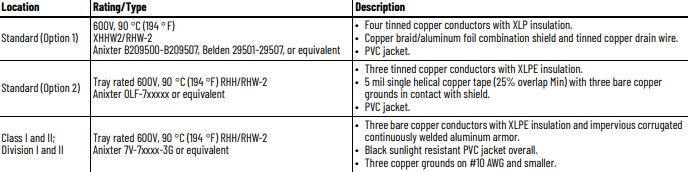
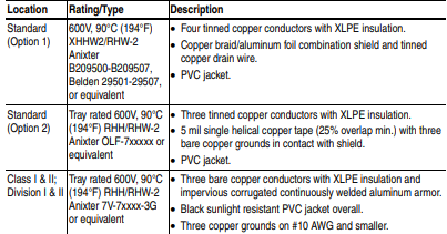
Cable Recommendations
Power Cable Types Acceptable for 200…600 Volt Installations
Various cable types are acceptable for drive installations. For many installations, unshielded cable is adequate, provided it can be separated
from sensitive circuits. As an approximate guide, allow a spacing of 0.3 meters (1 foot) for every 10 meters (32.8 feet) of length. In all cases,
long parallel runs must be avoided. Do not use cable with an insulation thickness less than or equal to 15 mils (0.4mm/0.015 in.). Use Copper
wire only. Wire gauge requirements and recommendations are based on 75 °C (167 °F). Do not reduce wire gauge when using higher
temperature wire. See table below.
Unshielded
THHN, THWN or similar wire is acceptable for drive installation in dry environments provided adequate free air space and/or conduit fill rates
limits are provided. Do not use THHN or similarly coated wire in wet areas. Any wire that is chosen must have a minimum insulation
thickness of 15 mils and should not have large variations in insulation concentricity.
Shielded/Armored Cable
Shielded cable contains all general benefits of multi-conductor cable with the added benefit of a copper braided shield that can contain
much of the noise that is generated by a typical AC drive. Strong consideration for shielded cable should be given in installations with
sensitive equipment such as weigh scales, capacitive proximity switches and other devices that may be affected by electrical noise in the
distribution system. Applications with large numbers of drives in a similar location, imposed EMC regulations or a high degree of
communications/ networking are also good candidates for shielded cable.
Shielded cable may also help reduce shaft voltage and induced bearing currents for some applications. In addition, the increased impedance
of shielded cable may help extend the distance that the motor can be located from the drive without the addition of motor protective devices
such as terminator networks.
Consideration should be given to all general specifications that are dictated by the environment of the installation, including temperature,
flexibility, moisture characteristics and chemical resistance. In addition, a braided shield should be included and be specified by the cable
manufacturer as having coverage of at least 75%. An additional foil shield can greatly improve noise containment.
A good example of recommended cable is Belden 295xx (xx determines gauge). This cable has four (4) XLPE insulated conductors with a
100% coverage foil and an 85% coverage copper braided shield (with drain wire) surrounded by a PVC jacket.
Other types of shielded cable are available, but the selection of these types may limit the allowable cable length. Particularly, some of the
newer cables twist four conductors of THHN wire and wrap them tightly with a foil shield. This construction can greatly increase the cable
charging current required and reduce the overall drive performance. Unless specified in the individual distance tables as tested with the
drive, these cables are not recommended and their performance against the lead length limits supplied is not known.
Maximum Motor Cable Lengths
For information on maximum motor cable lengths, see the Wiring and Grounding Guidelines for Pulse Width Modulated (PWM) AC Drives,
publication DRIVES-IN001.
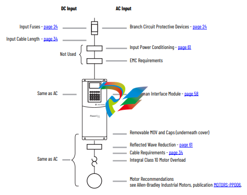
Power Wiring
The PowerFlex 700 has the following built in protective features to help simplify installation:
• Ground fault protection during startup and running ensures reliable operation
• Electronic motor overload protection increases motor life
• Removable MOV to ground and common mode capacitors to ground ensure compatibility with ungrounded systems. These devices
must be disconnected if the drive is installed on a resistive grounded distribution system, an ungrounded distribution system, a B
phase grounded distribution system or impedance grounded system. These devices must also be disconnected if the drive power
source is a regenerative unit (such as a bus supply and brake) or is DC fed from an active converter.
• 6 kV transient protection provides increased robustness for 380…480V system voltages
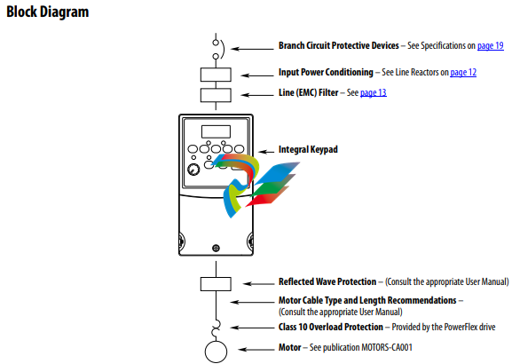
There are many other factors that must be considered for optimal performance in any given application. The block diagram below highlights
the primary installation considerations. Consult the Wiring and Grounding Guidelines for Pulse Width Modulated (PWM) AC Drives, publication
DRIVES-IN001 for detailed recommendations on input power conditioning, dynamic braking, reflected wave protection and motor cable
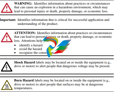
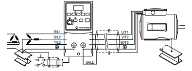
ATTENTION: PowerFlex 40 drives contain protective MOVs that are
referenced to ground. These devices must be disconnected if the drive is
installed on an ungrounded or resistive grounded distribution system.
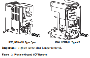
Disconnecting MOVs
To prevent drive damage, the MOVs connected to ground shall be
disconnected if the drive is installed on an ungrounded distribution
system where the line-to-ground voltages on any phase could exceed
125% of the nominal line-to-line voltage. To disconnect these devices,
remove the jumper shown in the Figures 1.1 and 1.2.
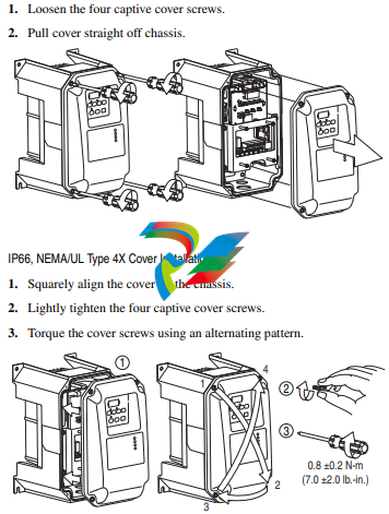
1. Turn the screw counterclockwise to loosen.
2. Pull the jumper completely out of the drive chassis.
3. Tighten the screw to keep it in place.
Figure 1.1 Jumper Location (Typical)
Solid state equipment has operational characteristics differing from those of
electromechanical equipment. Safety Guidelines for the Application, Installation
and Maintenance of Solid State Controls (Publication SGI-1.1 available from your
local Rockwell Automation sales office or online at http://
www.rockwellautomation.com/literature) describes some important differences
between solid state equipment and hard-wired electromechanical devices. Because
of this difference, and also because of the wide variety of uses for solid state
equipment, all persons responsible for applying this equipment must satisfy
themselves that each intended application of this equipment is acceptable.
In no event will Rockwell Automation, Inc. be responsible or liable for indirect or
consequential damages resulting from the use or application of this equipment.
The examples and diagrams in this manual are included solely for illustrative
purposes. Because of the many variables and requirements associated with any
particular installation, Rockwell Automation, Inc. cannot assume responsibility or
liability for actual use based on the examples and diagrams.
No patent liability is assumed by Rockwell Automation, Inc. with respect to use of
information, circuits, equipment, or software described in this manual.
Reproduction of the contents of this manual, in whole or in part, without written
permission of Rockwell Automation, Inc. is prohibited.
Throughout this manual, when necessary we use notes to make you aware of safety
considerations
Allen-Bradley, Rockwell Automation, and PowerFlex are registered trademarks of Rockwell Automation, Inc. DriveExplorer, DriveExecutive, and SCANport are trademarks of Rockwell Automation, Inc. PLC is a registered trademark of Rockwell Automation, Inc
The information below summarizes the changes to the PowerFlex 40 User Manual since the August 2008 release.
Description of New or Updated Information Page(s)
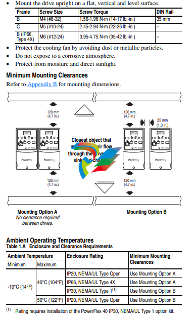
Minimum Enclosure Volume column and new footnotes added. 1-9, A-2
Read this document and the documents listed in the additional resources section about installation, configuration, and
operation of this equipment before you install, configure, operate, or maintain this product. Users are required to familiarize
themselves with installation and wiring instructions in addition to requirements of all applicable codes, laws, and standards.
Activities including installation, adjustments, putting into service, use, assembly, disassembly, and maintenance are required to
be carried out by suitably trained personnel in accordance with applicable code of practice.
If this equipment is used in a manner not specified by the manufacturer, the protection provided by the equipment may be
impaired.
In no event will Rockwell Automation, Inc. be responsible or liable for indirect or consequential damages resulting from the use
or application of this equipment.
The examples and diagrams in this manual are included solely for illustrative purposes. Because of the many variables and
requirements associated with any particular installation, Rockwell Automation, Inc. cannot assume responsibility or liability for
actual use based on the examples and diagrams.
No patent liability is assumed by Rockwell Automation, Inc. with respect to use of information, circuits, equipment, or software
described in this manual.
Reproduction of the contents of this manual, in whole or in part, without written permission of Rockwell Automation, Inc., is
prohibited.
Throughout this manual, when necessary, we use notes to make you aware of safety considerations.
About This Publication This document provides procedural information for managing daily or
recurring tasks involving the PowerFlex® 7000 medium voltage ‘B’ frame
drives (heatsink and heatpipe models).
Download Firmware, AOP,
EDS, and Other Files
Download firmware, associated files (such as AOP, EDS, and DTM), and access
product release notes from the Product Compatibility and Download Center at
rok.auto/pcdc.
Summary of Changes This publication contains the following new or updated information. This list
includes substantive updates only and is not intended to reflect all changes.
Who Should Use This
Manual
This manual is intended for use by personnel familiar with medium voltage
and solid-state variable speed drive equipment. The manual contains material
that enables regular operation and maintenance of the drive system.
What Is Not in This Manual This manual provides information specific to maintaining the PowerFlex 7000
‘B’ frame drive. This document does not include topics such as:
• Physically transporting or siting the drive cabinetry
• Installing or commissioning procedures
• Spare parts lists compiled for your order.
Rockwell Automation provides the site- and installation-specific electrical and
design information for each drive during the order process cycle. If they are
not available on site with the drive, contact Rockwell Automation.
If you have multiple drive types or power ranges, ensure you have the correct
documentation for each specific PowerFlex 7000 product:
• ‘A’ frame for lower-power air-cooled, configurations (up to
approximately 1250 hp/933 kW)
• ‘B’ frame for higher-power, air-cooled configurations (standard or
heatpipe models)
• ‘C’ frame for all liquid-cooled configurations
PowerFlex 7000 Drive Overview
The PowerFlex™ 7000 drive is a general-purpose, standalone, medium voltage
drive that controls speed, torque, direction, starting, and stopping of standard
asynchronous or synchronous AC motors. This drive works on numerous
standard and specialty applications such as fans, pumps, compressors, mixers,
conveyors, kilns, fan-pumps, and test stands in industries such as
petrochemical, cement, mining and metals, forest products, power generation,
and water/waste water.
The PowerFlex 7000 drive meets most common standards from these
organizations:
• National Electrical Code (NEC)
• International Electrotechnical Commission (IEC)
• National Electrical Manufacturers Association (NEMA)
• Underwriters Laboratories (UL)
• Canadian Standards Association (CSA).
The drive is available with the world’s most common supply voltages at
medium voltage, from 2400…6600V. The design focuses on high reliability,
ease of use, and lower total cost of ownership.
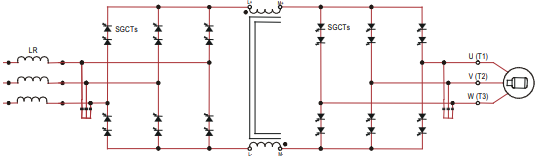
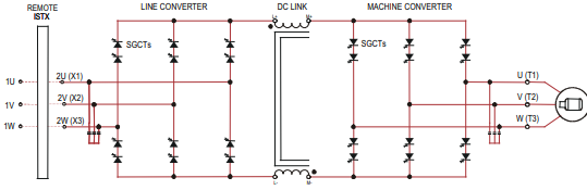
Topology The PowerFlex 7000 drive uses a pulse width modulated (PWM) – current
source inverter (CSI) topology. This topology applies to a wide voltage and
power range. The power semiconductor switches used are easy-to-series for
any medium voltage level. Semiconductor fuses are not required for the power
structure due to the current limiting DC link inductor.
With 6500V PIV rated power semiconductor devices, the number of inverter
components is minimal. For example, only six inverter switching devices are
required at 2400V, 12 at 3300…4160V, and 18 at 6600V.
The PowerFlex 7000 drive also provides inherent regenerative braking for
applications where the load is overhauling the motor, or where high inertia
loads are quickly slowed down. The drive uses the following:
• Symmetrical gate commutated thyristors (SGCTs) for machine converter
switches
• SGCTs for active front-end (AFE) rectifier configurations for the line
converter switches
• Silicon-controlled rectifiers (SCRs) for 18-pulse rectifier configurations
The PowerFlex 7000 drive provides a selectable option for enhanced torque
control capabilities and increased dynamic control performance. This highperformance torque control (HPTC) feature delivers 100% torque at zero speed
and provides torque control through zero speed with smooth direction
transition.
Rectifier Designs Configurations
The PowerFlex 7000 drive offers three rectifier configurations for ‘B’ frame
drives:
• Direct-to-Drive™ (AFE rectifier with integral line reactor and CMC)
• AFE rectifier with separate isolation transformer
• 18-pulse rectifier with separate isolation transformer
Direct-to-Drive
Direct-to-Drive technology does not require an isolation transformer or
multiple rectifier bridges as in voltage source inverter (VSI) topologies offered
by others. The approach is completely different. Instead of multiple
uncontrolled rectifiers, a single AFE rectifier bridge is supplied. The rectifier
semiconductors that are used are SGCTs. Unlike the diodes that are used in
VSI rectifier bridges, SGCTs are turned on and off by a gating signal. A PWM
gating algorithm controls the firing of the rectifier devices, similar to the
control philosophy of the inverter. The gating algorithm uses a specific
42-pulse switching pattern called selective harmonic elimination (SHE) to
mitigate the 5th, 7th, and 11th harmonic orders
A small integral line reactor and capacitor addresses the high harmonic orders
(13th and above) and provides virtually sinusoidal input voltage and current
waveforms back to the distribution system. This configuration delivers
excellent line-side harmonic and power factor performance to meet IEEE 519-
1992 requirements and other global harmonic standards in virtually all cases.
This setup also provides a simple, robust power structure that maximizes
uptime by minimizing the number of discrete components and the number of
interconnections required.
A CMC mitigates the common mode voltage seen at the motor terminals, so
standard (non-inverter duty rated) motors and motor cables can be used. This
technology is ideal for retrofitting existing motor applications
AFE Rectifier with Separate Isolation Transformer
For applications when the line voltage is higher than the motor voltage, a
transformer is required for voltage matching. In this case, providing an AFE
rectifier with a separate isolation transformer is ideal (indoor and outdoor
transformer versions are offered). The isolation transformer replaces the
requirement for an integral line reactor and replaces the requirement for a
CMC that is supplied in the Direct-to-Drive rectifier configuration. However,
the AFE rectifier, its operation, and advantages are the same as the Direct-toDrive configuration.
Figure 3 – 3300/4160 AFE Rectifier with Separate Isolation Transformer
For high power constant torque applications and/or when the line voltage is
higher than the motor voltage, a transformer is required for voltage matching
(indoor and outdoor transformer options are available). The 18-pulse rectifier
uses SCRs instead of the SGCTs used for an AFE rectifier. When used for high
power constant torque applications, the 18-pulse rectifier has lower losses than
the AFE rectifier, making 18-pulse ideal for the highest power requirements.
The 18-pulse isolation transformer provides the required input impedance and
addresses common mode voltage just like the separate isolation transformer
used with the AFE rectifier. However, instead of a PWM rectifier switching
pattern and a single rectifier bridge, the 18-pulse configuration mitigates line
side harmonics through harmonic current cancellation in the isolation
transformer phase shifted secondary windings. The inverter is the same
configuration for all available rectifier options.
Figure 4 – 3300/4160V 18-pulse Rectifier with Separate Isolation Transformer
Cooling Technology These VFDs are supplied with heatsinks for most configurations and heatpipes
for the highest-power AFE configurations. While both configurations draw
heat away from the semiconductors, heatpipes are bigger, more efficient, and
require larger fans and airflow.
Information and graphics in this manual show both configurations.
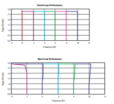
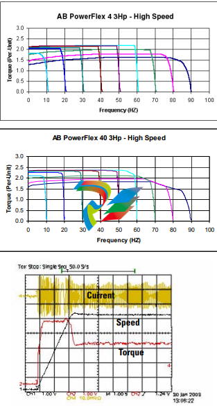
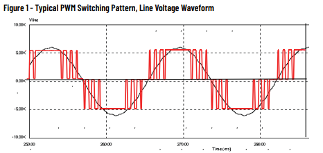
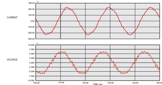
Motor Compatibility The PowerFlex 7000 drive achieves near-sinusoidal current and voltage
waveforms to the motor, resulting in no significant additional heating or
insulation stress. Temperature rise in the motor connected to the VFD is
typically 3 °C (5.5 °F) higher compared to across-the-line operation. Voltage
waveform has dv/dt of less than 50 V/μs. The peak voltage across the motor
insulation is the rated motor RMS voltage divided by 0.707.
Reflected wave and dv/dt issues often associated with VSI drives are a nonissue with the drive. Figure 5 shows typical motor waveforms. The drive uses a
SHE pattern in the inverter to eliminate major order harmonics, plus a small
output capacitor (integral to the drive) to eliminate harmonics at higher
speeds.
Standard motors are compatible without de-rating, even on retrofit
applications.
Motor cable distance is virtually unlimited. Rockwell Automation has tested
this technology for controlling motors up to 15 km (9.3 mi) away from the drive.
Figure 5 – Motor Waveforms at Full Load, Full Speed
Power Component Definition and Maintenance
This section provides an overview of the control components and cabling of
your PowerFlex® 7000 ‘B’ frame drive. This section also details a number of
regular or recurring maintenance tasks that will keep your drive in peak
operating condition.
Figure 20 through Figure 26 identify the control components and cabling of
your drives. Where appropriate, separate diagrams and instructions are
available for both the heatsink and the heatpipe ‘B’ frame models.
For information regarding power wiring and cabling connections (as might be
necessary for routine maintenance), see the PowerFlex 7000 ‘B’ frame
installation manual, publication 7000-IN007.
Control Power Off Tests Perform the following checks before applying control power to the drive.
Rockwell Automation recommends that you complete these checks in the
sequence they are presented here.
Interlocking
When the input contactor option is purchased, a key interlock is provided to
prevent access to the medium voltage compartments of the drive unless the
input isolation switch is locked in the open position.
Where the input switching device is provided by others, Rockwell Automation
will provide a key interlock on the medium voltage compartment of the drive,
and a matching interlock for installation by others on the upstream device. The
interlock shall be installed in a manner that ensures the power to the drive is
off and the drive is electrically isolated whenever the key is freed.
Although key interlocks shipped with all medium voltage equipment are
aligned in the factory, they often move out of position during shipping or are
often misaligned when the cabinet is set down on an uneven floor.
ATTENTION: Servicing energized industrial control equipment can be
hazardous. Severe injury or death can result from electrical shock,
burn, or unintended actuation of control equipment. Hazardous
voltages can exist in the cabinet even with the circuit breaker in the
off position. We recommend that you disconnect or lock out control
equipment from power sources, and confirm discharge of stored
energy in capacitors. If you must work in the vicinity of energized
equipment, the safety-related work practices of NFPA 70E, Standard
for Electrical Safety in the Workplace, must be followed
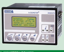
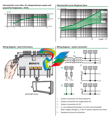
The IRDH575 monitors for ground faults in ungrounded AC (20 – 760 V, single- and threephase) and DC (20 – 575 V) by measuring the system’s insulation resistance. Systems with
extensive power conversion devices, such as rectifiers and variable frequency drives, are
supported by the IRDH575. The IRDH575 is able to detect ground faults in ungrounded
systems before leakage current may even be present.
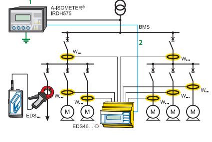
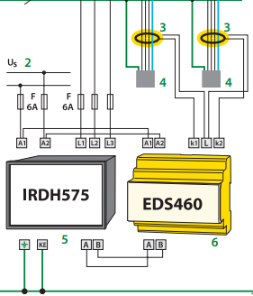
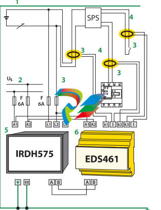
When combined with EDS4… ground fault location devices and the appropriate current
transformers, the IRDH575 becomes a controller for a ground fault location system.
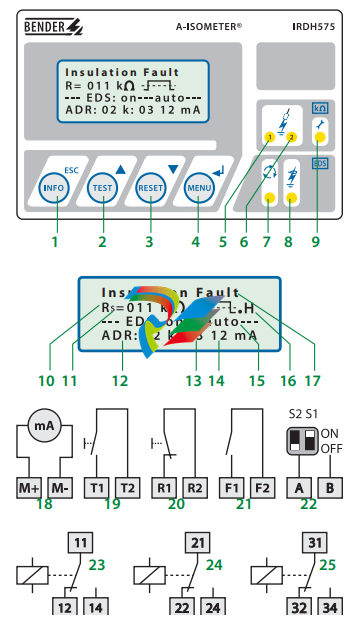
Function: Ground fault detection
When the insulation resistance from system to ground falls below the set response value,
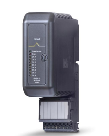
the alarm relays switch and the alarm LEDs activate. Two separately adjustable alarm
contacts can be set to a prewarning and main warning alarm. The measured value is indicated on the LCD display or on an externally connected meter. If the device is set to nonlatching mode, the alarms will clear when the ground fault clears. If the device is set to
latching mode, the alarms will not reset until the device is reset manually or the supply
voltage is lost. An external and internal test/reset can be activated remotely or on the device. A comprehensive INFO menu key displays additional information such as the current leakage capacitance and device settings.
The IRDH575 continuously monitors the equipment ground connection and line connections to ensure proper operation. The device’s easy-to-use onboard menu manages all
settings via the detailed LCD screen.
Function: Ground fault location
When a ground fault is detected, the EDS ground fault location system is activated (this
feature can be set to require a manual start as well). Each channel of the EDS location device is connected to a particular branch circuit. The IRDH575 begins transmitting a pulsed
signal. This signal will travel through the channel of the EDS with the ground fault back
to the IRDH575. If the pulse travels back to the IRDH575, the channel with the ground
fault will display on both the IRDH575 and the EDS device.
In addition, an optional EDS30… portable ground fault location system can be used to follow the pulse travelling to the source of the ground fault.
Additional functions
99 timestamped alarm messages may be stored in the non-volatile memory of the
IRDH575. The device also includes standby contacts when several A-ISOMETER® detectors
are operating in coupled ungrounded systems.
Two-way data communication is carried out between devices via an RS-485 interface.
This interface can be connected to a BENDER protocol converter to exchange data across
other protocols, such as Ethernet, MODBUS, or PROFIBUS.
A 0/4 – 20 mA output can be connected to an external meter or higher-level control system, such as a PLC.
System design
Each isolated system requires one IRDH575 for ground fault detection and location control. Up to 90 EDS46… devices can be interconnected to the IRDH575. Each EDS device
can monitor up to 12 separate channels. An optional EDS30…. portable ground fault location system can be used in conjunction with the IRDH575/EDS46… system.
1 – INFO key: Displays pertinent system information
This manual does not contain all the information required to operate and maintain
the product. Refer to the following manuals for other required information.
3500 Monitoring System Rack Configuration and Utilities Guide
(129777-01)
• guidelines for using the 3500 Rack Configuration software for setting the operating
parameters of the module
• guidelines for using the 3500 test utilities to verify that the input and output
terminals on the module are operating properly
3500 Monitoring System Computer Hardware and Software Manual
(128158-01)
• instructions for connecting the rack to 3500 host computer
• procedures for verifying communication
• procedures for installing software
• guidelines for using Data Acquisition / DDE Server and Operator Display Software
• procedures and diagrams for setting up network and remote communications
3500 Field Wiring Diagram Package (130432-01)
• diagrams that show how to hook up a particular transducer
• lists of recommended wiring
Operation and Maintenance Manuals for all the modules installed in the
rack
Product Disposal Statement
Customers and third parties, who are not member states of the European Union, who are
in control of the product at the end of its life or at the end of its use, are solely
responsible for the proper disposal of the product. No person, firm, corporation,
association or agency that is in control of product shall dispose of it in a manner that is
in violation of any applicable federal, state, local or international law. Bently Nevada LLC
is not responsible for the disposal of the product at the end of its life or at the end of its
use.
1. Receiving and Handling Instructions
This will be a short overview of the entire section.
1.1 Receiving Inspection
Visually inspect the system for obvious shipping damage. If you detect shipping
damage, file a claim with the carrier and submit a copy to Bently Nevada, LLC.
1.2 Handling and Storage Considerations
Proper handling and storing of printed circuit boards is extremely critical. Circuit
boards contain devices that are susceptible to damage when exposed to
electrostatic charges. Damage caused by obvious mishandling of the board will
void the warranty. To avoid damage, observe the following precautions in the
order given.
Application Advisory
Machinery protection will be lost when
you remove all power from the rack.
• Do not discharge static electricity onto the circuit board. Avoid tools or
procedures that would subject the circuit board to static damage.
Some possible causes of static damage include ungrounded soldering
irons, nonconductive plastics, and similar materials.
• Use a suitable grounding strap (such as 3M Velostat® No. 2060) to
ground yourself before handling or performing maintenance on a
printed circuit board.
• Transport and store circuit boards in electrically conductive bags or
foil.
• Use extra caution during dry weather. Relative humidity less than 30%
tends to multiply the accumulation of static charges on any surface.
When performed properly, you may remove modules from or install modules into
the rack while power is applied to the rack. Refer to << Section reference to
“Module Installation in section 4 >> for the proper procedure
2. General Information
Monitoring and computerized vibration information systems provide the
information you need to assess the mechanical condition of rotating and
reciprocating machinery. These systems continuously measure and monitor
various supervisory parameters and provide crucial information for early
identification of machinery problems such as imbalance, misalignment, shaft
crack, and bearing failures. As such, these systems are an efficient and effective
means of satisfying plant management, engineering, and maintenance concerns
for:
• Increasing plant safety by minimizing the occurrence of hazardous
conditions or catastrophic failures.
• Improving product quality by minimizing process variances caused by
improperly operating equipment.
• Maximizing plant availability by servicing only those machines that
require it and providing more efficient turnarounds.
• Reducing plant operating costs by minimizing unplanned shutdowns
and by making more efficient use of maintenance resources.
For protection of critical machinery, we highly recommend that you permanently
install continuous monitoring systems. The term “protection” means that the
system can shut down machinery on alarm, without human interaction. These
systems include applicable transducers, each with its own dedicated monitoring
circuitry and alarm setpoints. The 3500 Monitoring System is the newest addition
to the family of continuous monitoring systems offered by Bently Nevada, LLC.
2.1 3500 Monitoring System
The 3500 is a full-feature monitoring system whose design incorporates the latest
in proven processor technology. In addition to meeting the above stated criteria,
the 3500 adds benefit in the following areas:
• Enhanced operator information
• Improved integration to plant control computer
• Reduced installation and maintenance cost
• Improved reliability
• Intrinsic Safety (IS) option
The following sections discuss these benefits in more detail.
2.1.1 Enhanced Operation Information
The 3500 design includes features to both enhance the operator’s information
and present this information so that the operator may easily interpret it. These
features include:
• Improved data set
– Overall amplitude
– Probe gap voltage
– 1X amplitude and phase
– 2X amplitude and phase
– Not 1X amplitude
• Windows®-based Operator Display Software
• Data displayed at multiple locations
2.1.2 Improved Integration to Plant Control Computer
The 3500 improves integration to the plant control computer with:
• Communication Gateways supporting multiple protocols
• Time synchronized vibration and process information
2.1.3 Reduced Installation and Maintenance Costs
The 3500 system provides the following cost-saving features:
• Reduced cabling costs
• Downward product compatibility
• Improved space utilization
• Easier configuration
• Reduced spare parts
• Improved serviceability
2.1.4 Improved Reliability
The 3500 offers several features to improve system reliability.
• Redundant power supplies available
• Triple Modular Redundant (TMR) monitors and relay cards available
• Redundant Gateway and Display Modules permitted
2.1.5 Intrinsic Safety Option
If you wish to monitor equipment that is located in hazardous atmospheres, the
3500 Monitoring System has a range of I/O modules with internal zener barriers.
These modules provide an Intrinsically Safe interface between the 3500 rack and
the transducers located in the hazardous area.
2.1.6 Multiple Output Interfaces
You can conveniently adjust monitor options (such as full scale ranges,
transducer inputs, recorder outputs, alarm time delays, alarm voting logic, and
relay configuration) in the field via software. Modular system design employs
plug-in components which allow easy servicing and expansion.
The following three independent interfaces are available with the 3500 system:
• Data Manager Interface (Transient Data Interface External or Dynamic
Data Interface External)
• Configuration/Data port
• Communications Gateway (support for Programmable Logic
Controllers, Process Control Computers, Distributed Control Systems,
and PC-based Control Systems)
These interfaces allow you to easily view monitored parameters and their
statuses in the following ways:
• System 1® Software
• Bently Nevada™ 3500 Operator Display Software
• Remote display panel
• DCS or PLC display
Convenient front panel coaxial connectors provide dynamic transducer signals
and allow you to connect diagnostic or predictive maintenance instruments.
2.2 Common Features
The common features of the modules in the 3500 rack include hot insertion or
removal of modules and external and internal termination of the wiring.
2.2.1 Hot Insertion or Removal of Modules
When performed properly, you can remove and replace any module while the
system is under power without affecting the operation of any unrelated modules.
If the rack has 2 power supplies, removing or inserting a power supply will not
disrupt the operation of the 3500 rack. See <<Section reverence: “Module
Installation in section 4 >> for the proper procedure.
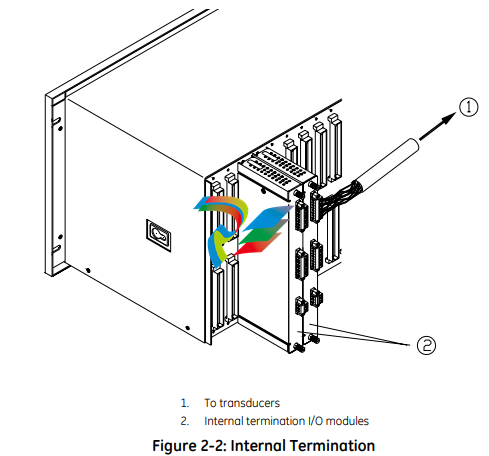
2.2.2 External and Internal Termination
External termination uses multi-conductor cables to connect the I/O modules to
the terminal blocks. These blocks simplify connecting many wires to the rack in
tight areas. External termination is not available on I/O modules with internal
zener barriers.
Internal termination lets you connect transducers directly to the I/O modules.
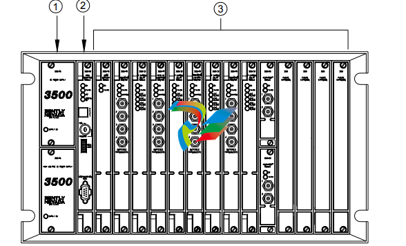
3500 System Components
The 3500 Monitoring System consists of modules that fit into a rack. Figure 2-3
shows a full-size 3500 system rack and system components. Note that the fullsize rack has 14 monitor slot positions. The Mini-rack (not shown) is similar, but
has 7 monitor slot positions to the right of the power supplies and Rack Interface
Module.
1. 1 or 2 power supplies
2. Rack Interface Module (standard, Transient Data Interface, (TDI), Triple Modular Redundant (TMR) and TMR TDI)
3. Monitoring slot positions:
– Monitor module
– Keyphasor® module (2 maximum)
– Relay module
– Communication Gateway module
– Display module. For the System Face Mount you must install the Display Interface Module in Slot 15.
– 3500/04-01 Earthing Module. Intallations that use Inernal Barrier I/Os require 1 Earthing Module per rack.
Figure 2-3: 3500 Rack (Full-Size)
The following sections list the function of each module. Refer to the individual
operation and maintenance manuals for available options, detailed description,
operation and maintenance.
2.3.1 Weatherproof Housing
The weatherproof housing protects the 3500 rack from adverse environmental
effects, such as excessive moisture, dirt and grime, and even unclean air. The
weatherproof housing will not accommodate a Display Unit or VGA Display.
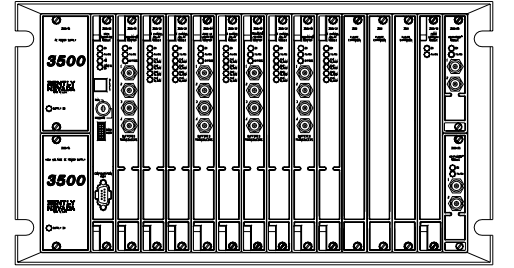
2.3.2 Rack
2 types of 3500 racks are available: the full-size 19-inch rack and the compact 12-
inch Mini-rack. Each rack requires you to install the Power Supplies and Rack
Interface Module (RIM) in specific locations. The full-size version offers 14
additional rack positions and the Mini-rack offers 7 additional rack positions. You
may use these positions to install any combination of modules. Both racks
support Standard (non-redundant) and Triple Modular Redundant (TMR)
configurations
Application Advisory
The TMR system will restrict the
location of certain modules.
2.3.3 Power Supply
The Power Supply is a half-height module available in ac and dc versions. You
can install 1 or 2 power supplies in the rack. Each power supply can power a fully
loaded rack. When you install 2 power supplies in a rack, the supply in the lower
slot acts as the primary supply and the supply in the upper slot acts as the
backup supply. If the primary supply fails, the backup supply will provide power to
the rack without interrupting rack operation. The 3500 design allows you to
install any combination of power supply types.
Overspeed Detection and TMR Monitors require dual power supplies.
2.3.4 Rack Interface Module
The Rack Interface Module (RIM) is a full-height module that communicates with
the host (computer), a Bently Nevada™ Communication Processor, and the other
modules in the rack. The Rack Interface Module also maintains the System Event
List and the Alarm Event List. You can daisy-chain this module to the Rack
Interface Modules in other racks and to the Data Acquisition / DDE Server
Software. The 3500 Monitoring System Computer Hardware and Software Manual
shows how to daisy chain the Rack Interface Modules together. Rack Interface
Modules are available in Standard, Triple Modular Redundant and Transient Data
Interface versions.
2.3.5 Communication Gateway Module
The Communication Gateway Module is a full-height module that allows external
devices (such as a DCS or a PLC) to retrieve information from the rack and to set
up portions of the rack configuration. You can install more than one
Communication Gateway Module in the same rack. Communication Gateway
Modules are available for a variety of network protocols.
2.3.6 Monitor Module
The Monitor Modules are full-height modules that collect data from a variety of
transducers. You can install any combination of Monitor Modules in the 3500
rack.
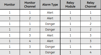
2.3.7 Relay Module
Relay Modules provide relays that you can configure to close or open based on
channel statuses from other monitors in the 3500 rack. Relay modules are
available in 4-channel, 16-channel, and 4-channel Triple Modular Redundant
(TMR) versions.
The TMR Relay Module is a half-height 4-channel module that operates in a TMR
system. 2 half-height TMR Relay Modules must operate in the same slot. If you
remove the upper or lower Relay Module or the system declares one of the
modules as Not OK, then the other Relay Module will control the Relay I/O Module.
2.3.8 Keyphasor® Module
The Keyphasor Module is a half-height module that provides power for the
Keyphasor transducers, conditions the Keyphasor signals, and sends the signals
to the other modules in the rack. The Keyphasor Module also calculates the rpm
values sent to the host (computer) and external devices (DCS or PLC) and provides
buffered Keyphasor outputs. Each Keyphasor Module supports 2 channels. You
may place up to 2 Keyphasor Modules in a 3500 rack for a maximum of 4
Keyphasor channels. If you use 2 Keyphasor Modules, you must place them in the
same full-height slot and the modules will share a common I/O module.
2.3.9 Display Module
The 3500 system offers multiple display options.
The Display Interface Module can display rack data on an LCD-based Interface
unit or a 3rd-party Modbus® based display unit.
The VGA Display Module will display rack data on certain touch screen VGA
Displays.
The Integrated PC display is a complete rack mount touch screen PC pre-loaded
with rack configuration software and display utilities.
2.3.10 Earthing Module
The Earthing Module is a full-height module that provides a low resistance
connection (must be less than 1 Ω) from the 3500 rack to the plant’s intrinsically
safe earth ground. The module operates in conjunction with the 3500 internal
zener barrier I/O modules. Your application will require 1 Earthing Module per rack
when internal barrier I/O modules are used.
2.4 Standard Rack Relay Options
You can configure the standard (or non-TMR) 3500 rack to have individual relays,
bussed relays, or a combination of individual and bussed relays.
2.4.1 Individual Relays
A rack with individual relays contains 1 or more relay cards for each monitor
module. You can configure the monitor and relay modules within a 3500 rack in
many ways.
Example 1: The application uses 1 relay module 1 monitor module
Table 2-1: 1 Relay Module Used With 1 Monitor Module
Figure 2-4: Typical Standard 3500 Rack with Individual Relays (Full-Size Rack Shown)
2.4.2 Bussed Relays
In the Bussed Relays configuration a number of monitor channels share a single
relay. Use the Rack Configuration Software to define the combination of alarms
that will trigger the relay. Figure 2-5 shows a typical Bussed Relay layout for a
standard 3500 rack. You can [place the monitors and relay modules in any slot as
long as you link the monitors to the relay module in the Rack Configuration
Software
3.7.4 Additional Notes
• Larger scale factors are less susceptible to EMI than smaller scale factors.
• Larger full-scales are less susceptible to EMI than smaller full-scale.
• Monitors with narrow bandwidth filter configurations are less susceptible to
EMI than monitors configured with wide bandwidth.
• Larger Keyphasor® or hysteresis settings are less susceptible to EMI than
smaller hysteresis settings.
• Shorter Alarm delay times may increase monitor susceptibility to transient
EMI.
• Environments with higher levels of EMI than tested may cause unpredictable
monitor readings and may cause system malfunction.
3.8 Set Rack Jumpers and Switches
Set the following jumpers and switches before operating the rack:
• Rack address switch (on the front of the Rack Interface Module)
• Transducer jumpers on each I/O Module, as required
• Certain I/O Modules have switches to control their mode of operation.
Examples include:
– RIM and Comm Gateway I/O’s that support both RS232 and
RS422 have a protocol selection switch
– Overspeed and non-TMR Relay I/O’s have Normally
Energized/De-energized Relay mode switches
– Comm Gateway I/O’s that support RS485 have termination
mode switches
• Setup phone connection to rack / host (if you use an internal or