Call us 24/7+86 15396210640
Welcome to the official website of Lingkong Automation Technology Co., Ltd!
Call us 24/7+86 15396210640

WATLOWCompact Loop System, Providing Powerful Control in a 1 /8 DIN Package

Watlow’s SERIES CLS200 is a powerful line of controllers, 

combining performance and flexibility with compact design. 

The 4, 8 and 16 loop versions provide complete controller 

solutions for a broad range of applications. Support for 

multiple types of sensor inputs is available, including 

thermocouples, RTDs, linear voltage, current and frequency. 

Each controller includes built-in serial communications 

for computer interface and data acquisition. Optional 

programmable ramp and soak features allow complex 

batch processing and sequencing. An enhanced feature 

option offers cascade control, ratio control, differential control, 

process variable retransmit and remote analog set point.

The SERIES CLS200 controllers are UL® and C-UL® listed, 

RoHS by design and meet the requirements of the European 

Community EMC Directive and carry the CE mark.

Features and Benefits

PID control of up to 16 heat and cool loops

• Minimizes panel space per loop 

• Reduces installation time

• Increases reliability: fewer parts means fewer failures

Auto-tune

• Requires less time tuning

• Achieves excellent control with less expertise

Menu-guided operation with full text display

• Allows quick setup of the controller

• Simplifies operation

Eight jobs stored and recalled

• Changes quickly from one process to another

Multiple and mixed inputs

• Accepts combinations of thermocouples, RTDs, linear dc 

voltage and linear dc current sensors

• Reduces learning curve and inventory

Sensor failure detection

• Reduces time troubleshooting reversed, shorted and 

open sensors

High/low process and deviation alarms for each input

• Integrates as needed with other automation controllers

34 digital outputs

• Provides flexible configuration

• Allows use of outputs as needed for control and alarms

EIA/TIA-232 and 485 communications

• Connects to software for easy operation

• Allows integration with controllers and software

Firmware Options

Choose firmware with the features needed for the 

application:

• Standard—includes closed-loop PID control, auto-tune, 

alarms, job memory and failed sensor detection.

• Ramp and soak—includes the standard firmware 

features with the addition of ramp and soak and process 

variable retransmit. Each channel can be configured for 

standard PID control or ramp and soak operation. Unused 

control outputs on any channel can be configured to 

retransmit a process value.

• Enhanced features— includes the standard firmware 

features with the addition of process variable retransmit, 

remote analog set point, cascade control, ratio control 

and differential control algorithms. Each channel can be 

configured for standard PID controller or one of the other 

control algorithms. Each channel of cascade control or 

remote analog set point requires two controller channels. 

Unused control outputs on any channel can be 

configured to retransmit a process value.

• Custom— application-specific, engineered solutions are 

available. Contact your Watlow representative.

Digital Input/Output Options

Controllers with the mass termination option for digital 

I/O termination have a 50-pin SCSI connector which allows 

access to all digital inputs and outputs. SCSI cables and the 

TB50 digital I/O termination board options are offered to 

allow connection of field wiring.

Four and eight loop controllers can be configured with 

screw terminal connections on the back for connecting 

digital inputs and outputs, but this limits access to 

15 outputs (10 of which can be used for control loops) 

and three inputs.

Because the SERIES CLS200 has no onboard analog 

outputs, applications that use process variable retransmit 

typically require one SDAC module per retransmitted 

signal.

DAC and SDAC Modules

The optional DAC and SDAC modules are available for

Watlow SERIES CLS200 controllers.

DAC

The DAC (digital to analog converter) converts one or two 

of the controller’s distributed zero crossing (DZC) output 

signals to analog signals. Each output is field configurable 

for 4-20mVDC, 0-5VDC or 0-10VDC.

SDAC

The SDAC (serial digital to analog converter) converts 

one controller output to a precise analog voltage or 

current signal. The unit is typically used for process 

variable retransmit, open-loop control, motor or belt speed 

control, or phase-angle fired SCR power controllers. The 

SDAC bears the CE mark and is UL® and C-UL® listed.

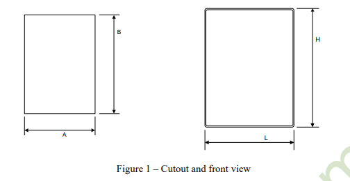
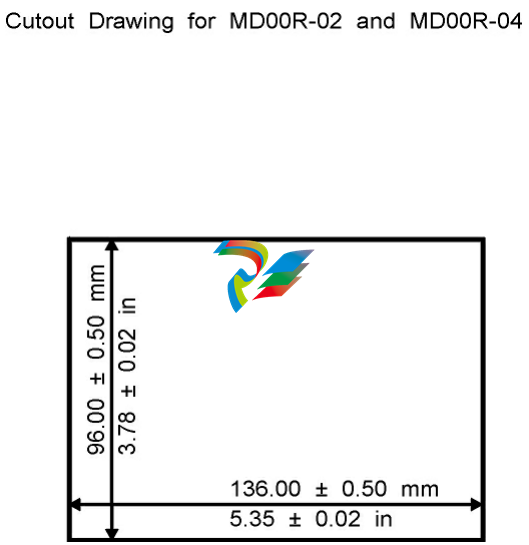
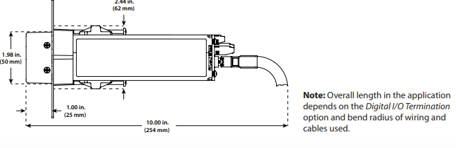
Dimensional Drawings

Figure 1 – TB18 Screw Terminals

Digital I/O Termination Option Shown

Figure 2 – TB50 Terminal Board Option

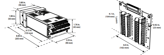
Figure 3 – Mass Termination (SCSI) Digital I/O Termination 

and Cable Options

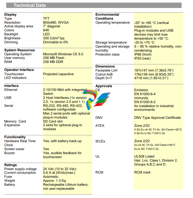
CLS200 Specifications

Operator Interface

• 32-character vacuum fluorescent display 

• 8-key keypad to access guided menus and prompts, 

enter passkey sequence, set values, switch between 

single channel and multiple channel displays

• Controller configuration can be loaded via serial 

communication

Analog Inputs

• 4-loop model: 4 differential inputs

• 8-loop model: 8 differential inputs

• 16-loop model: 16 single-ended inputs

Analog Over Voltage Protection

• ±20V referenced to digital ground

Maximum Common Mode Voltage

• 5V input to input or input to analog common 

(4- and 8-loop models)

Common Mode Rejection (CMR)

• For inputs that do not exceed ±5V, >60dB dc to 1kHz and 

120dB at selected line frequency 

Noise Rejection 

• 120dB at 60Hz

Sensors/Inputs

• Thermocouples: user-selectable type, direct connection, 

linearization, reference junction compensation, reversed 

and shorted thermocouple detection and upscale break 

protection with output averaging 

• RTD: (4 and 8 loop models only) 2- or 3-wire, platinum, 

100Ω @ 0°C, DIN 0.003850Ω/Ω/°C curve, user-selectable 

range. Two ranges offer different resolutions. Requires 

scaling resistors. See ordering information.

• Linear: current and voltage signals from linear transmitters 

• Pulse input

Input Range and Accuracy 

Sensor Range (°C) Range (°F) Accuracy

Type B 66 to 1760°C 150 to 3200°F ±4.0°C

Type E -200 to 787°C -328 to 1448°F ±1.0°C

Type J -212 to 760°C -350 to 1400°F ±1.2°C

Type K -268 to 1371°C -450 to 2500°F ±1.3°C

Type R -18 to 1766°C 0 to 3210°F ±2.8°C

Type S -18 to 1760°C 0 to 3200°F ±2.8°C

Type T -268 to 399°C -450 to 750°F ±1.6°C

RTDs available on CLS204 and CLS208 only.

Sensor Range (°C) Range (°F) Accuracy

RTD1 -100 to 275˚C -148 to 527˚F ±1.1˚C

RTD2 -120 to 840˚C -184 to 1544˚F ±1.6˚C

Note: Accuracy @ 25˚C ambient. Valid for 10 to 100 percent 

of span except Type B, which is specified for 800˚F to 

3200˚F. RTD.

Linear Voltage and Current Inputs

Requires scaling resistors. See ordering information.

0-20mAVDC/4-20mAVDC

0-5VDC

0-10VDC

Temperature coefficient: 40ppm/°C

Other ranges available. Contact factory. 

Pulse Input 

• One TTL-level square wave input up to 2kHz

Input Sampling Rate at 60Hz 

Each channel has the following scans per second:

• 4-loop model: 6 samples per second, 

(update time: 0.167 sec.)

• 8-loop model: 3 samples per second, 

(update time: 0.333 sec.)

• 16-loop model: 1.5 samples per second, 

(update time: 0.667 sec.)

Internal Measurement Resolution

• 0.006 percent, greater than 14 bits

Calibration

• Automatic zero and full scale

Digital Inputs 

• TTL-level used for selecting recipes or jobs, or R/S triggers

• 8 digital inputs and 1 pulse input with mass termination 

(SCSI) digital I/O termination and TB50 terminal board 

options

• 2 digital inputs and 1 pulse input with screw terminal 

(TB18) digital I/O termination option

Digital Outputs

• 34 digital outputs with mass termination (SCSI) digital I/O 

termination and TB50 terminal board options

• 11 control and alarm outputs with screw terminal (TB18) 

digital I/O termination option

• 1 or 2 control outputs are user assigned for each loop

• Each control output can be configured for on-off time 

proportioning, or distributed zero crossing

• Outputs sink up to 60mA each at 5VDC

• 350mA at 5VDC available from on-board supply 

Alarm Outputs 

• Independent process and deviation alarms for each 

channel

• Alarms can operate any output not used for control

• User-programmable deadband, delay and startup 

suppression

• Global alarm output activates when any alarm occurs

• Watchdog output indicates controller is functioning 

correctly

Serial Interface 

• EIA/TIA-232 or EIA/TIA-485 

Baud Rate

• 2400, 9600 or 19200, user-selectable

Communications Protocols

• Form of ANSI X3.28-1976, (D1, F1) compatible with 

Allen-Bradley PLC/2

• Modbus® RTU

Line Voltage/Power

• 15 to 24VDC ± 3VDC @ 1A (maximum),

300mA (no load)

Agency Approvals

• UL®, C-UL® listed: UL®61010-1 safety requirements for 

measurement, control and laboratory equipment

• CE Mark: See Declaration of Conformity for details

• RoHS by design

Ordering Information

Instructions: Choose one option for each feature

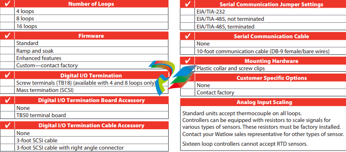
Note: To obtain a part number for your choice of options, communicate your selections to your Watlow sales representative who 

will provide a part number to you.

UNIOPUniOP eTOP05EB

The eTOP05EB is a cost-effective HMI device with touchscreen interface and 5.6” monochrome LCD 

display with 8 shades of grey. The enhanced graphical capabilities compared to the basic eTOP05 

make it the ideal choice for demanding applications on a limited budget. 

• 5.6” monochrome display

• 8 grey levels

• 1/4 VGA (320×240 pixel) resolution

• Resistive touchscreen

• Connection to industrial bus systems and 

Ethernet (requires optional plug-in modules) 

• 32 MB internal user memory

The eTOP HMI panels are part of the UniOP family of touchscreen products. All of the eTOP 

products support the rich common functionalities of the UniOP operator panels: 

• Powerful and intuitive programming with 

the UniOP Designer 6 software 

• Support of more than 130 communication 

drivers for industrial devices 

• Optional modules for fieldbus systems 

(Profibus DP, CANopen, DeviceNet, 

Interbus) and Ethernet. Ethernet modules 

allow connection to field devices as well 

as programming the HMI from Designer. 

• Dual-driver communication capability

• Vector graphic capabilities including the 

support of multiple layers and object 

transparency. 

• Display dynamic data in numerical, text, 

bargraph and graphic image formats 

• Data acquisition and trend presentation. 

Trend data can be transferred to a host 

computer using the Ethernet connection. 

• Analog gauge objects 

• Recipe data storage. Recipe data can be 

transferred to a host computer using the 

Ethernet connection. 

• Multilanguage applications. The number 

of runtime languages is limited only by the 

available memory. All text information in 

the application can be exported in Unicode 

format for easier translation. 

• Powerful macro editor to configure 

touchscreen operation 

• Alarms and historical alarm list. Alarm

and event information can be printed or 

transferred to a host computer using the 

Ethernet connection. 

• Eight level password protection. 

• Report printing to serial printer. Reports 

are freely configurable using Designer. 

• Ethernet-based UniNet network to share 

data between UniOP HMIs and to serve 

data using UniNet OPC Server. 

tn222-1.doc – 3.05.2006 

UniOP eTOP05EB 

Tech-note

UNIOPTech-note UniOP CP02F-02, CP02R-04

• Show up to 2 or 4 rows, 20 characters of 

information

• Choice of Vacuum Fluorescent or 

Monochrome LCD

• Up to 16 user programmable function keys 

with slide-in legends and LED indicators

• Connection to industrial bus systems and 

Ethernet with optional modules

• IP65 front panel protection

• Version with extended operating temperature 

available

Highlights 

The CP02 HMI panels are part of the UniOP family of entry-level products. They support the rich 

common functionality of the UniOP operator panels: 

• Powerful and intuitive programming with 

the UniOP Designer 6 software 

• Support of more than 130 communication 

drivers for industrial devices 

• Optional modules for fieldbus systems 

(Profibus DP, CANopen, DeviceNet, 

Interbus) and Ethernet. Ethernet modules 

allow connection to field devices as well 

as programming the HMI from Designer. 

• Dual-driver communication capability

• Display dynamic data in numerical and 

text formats 

• Recipe data storage. Recipe data can be 

transferred to an host computer using the 

Ethernet connection. 

• Multilanguage applications. The number 

of runtime languages is limited only by the 

available memory. All text information in 

the application can be exported in Unicode 

format for easier translation. 

• Powerful macro editor to configure 

touchscreen operation 

• Alarms and historical alarm list. Alarm

and event information can be printed or 

transferred to an host computer using the 

Ethernet connection. 

• Eight level password protection. 

• Report printing to serial printer. Reports 

are freely configurable using Designer. 

• Ethernet-based UniNet network to share 

data between UniOP HMIs and to serve 

data using UniNet OPC Server. 

tn227-0.doc – 3.11.2005 

UniOP CP02F-02, CP02R-04 1

StockChec

Note 1: the operating temperature of the version –00A8 is subject to the following restrictions: 

a) the panel can be operated in the temperature range -30°C to -20°C without damages but the display 

response may be very slow. 

b) regular display response requires a temperature of -20°C or higher 

c) powering the product for a period of at least 25 minutes at an enviroment temperature of -30°C 

will ensure that the internal temperature will increase to -20°C and then proper operation of the 

display will be ensured. 

Important note: 

operating at extreme temperatures it is very important to ensure that the Relative Humidity ratings are 

not exceeded. 

The product is designed for installation in industrial environments in compliance with the regulations: 

Emitted interference EN 61000-6-4, 2001 

Noise immunity EN 61000-6-2, 2001 

UNIOPUNIOPUniOP ePAD32B, ePAD33BandePAD33BT

UniOP ePAD32B, ePAD33B and ePAD33BT 

The ePAD32B, ePAD33B and ePAD33BT are state-of-the-art HMI devices with a VGA graphic 

display and a complete keypad. The aluminum bezel offers an appealing look in a rugged and 

convenient flat design. 

The product is also available with a touchscreen option. 

• 9.6” monochrome and 10.4” TFT color 

displays

• VGA (640×480 pixel) resolution

• 64K colors (ePAD33B and ePAD33BT)

• Resistive touchscreen (ePAD33BT)

• Connection to industrial bus systems and 

Ethernet (requires optional plug-in modules) 

• Compatible with video input module 

(ePAD33B and ePAD33BT) 

• 32 MB internal user memory

The ePAD3xB HMI panels are part of the UniOP family of HMI products. All of the ePAD products 

support the rich common functionalities of the UniOP operator panels: 

• Powerful and intuitive programming with 

the UniOP Designer 6 software 

• Support of more than 130 communication 

drivers for industrial devices 

• Optional modules for fieldbus systems 

(Profibus DP, CANopen, DeviceNet, 

Interbus) and Ethernet. Ethernet modules 

allow connection to field devices as well 

as programming the HMI from Designer. 

• Dual-driver communication capability 

• Vector graphic capabilities including the 

support of multiple layers and object 

transparency. 

• Video input option (ePAD33B and 

ePAD33BT) 

• Display dynamic data in numerical, text, 

bargraph and graphic image formats 

• Data acquisition and trend presentation. 

Trend data can be transferred to a host 

computer using the Ethernet connection. 

• Analog gauge objects 

• Recipe data storage. Recipe data can be 

transferred to a host computer using the 

Ethernet connection. 

• Multilanguage applications. The number 

of runtime languages is limited only by the 

available memory. All text information in 

the application can be exported in Unicode 

format for easier translation. 

• Powerful macro editor to configure 

touchscreen operation 

• Alarms and historical alarm list. Alarm 

and event information can be printed or 

transferred to a host computer using the 

Ethernet connection. 

• Eight level password protection. 

• Report printing to serial printer. Reports 

are freely configurable using Designer. 

• Ethernet-based UniNet network to share 

data between UniOP HMIs and to serve 

data using UniNet OPC Server. 

Note 1: the lamp lifetime is the typical value for continuous operation at 25ºC. 

The product is designed for installation in industrial environments in compliance with the regulations: 

Emitted interference EN 61000-6-4, 2001 

Noise immunity EN 61000-6-2, 2001 

UNIOPUniOP eTOP05EB

The eTOP05EB is a cost-effective HMI device with touchscreen interface and 5.6” monochrome LCD 

display with 8 shades of grey. The enhanced graphical capabilities compared to the basic eTOP05 

make it the ideal choice for demanding applications on a limited budget. 

• 5.6” monochrome display

• 8 grey levels

• 1/4 VGA (320×240 pixel) resolution

• Resistive touchscreen

• Connection to industrial bus systems and 

Ethernet (requires optional plug-in modules) 

• 32 MB internal user memory

The eTOP HMI panels are part of the UniOP family of touchscreen products. All of the eTOP 

products support the rich common functionalities of the UniOP operator panels: 

• Powerful and intuitive programming with 

the UniOP Designer 6 software 

• Support of more than 130 communication 

drivers for industrial devices 

• Optional modules for fieldbus systems 

(Profibus DP, CANopen, DeviceNet, 

Interbus) and Ethernet. Ethernet modules 

allow connection to field devices as well 

as programming the HMI from Designer. 

• Dual-driver communication capability

• Vector graphic capabilities including the 

support of multiple layers and object 

transparency. 

• Display dynamic data in numerical, text, 

bargraph and graphic image formats 

• Data acquisition and trend presentation. 

Trend data can be transferred to a host 

computer using the Ethernet connection. 

• Analog gauge objects 

• Recipe data storage. Recipe data can be 

transferred to a host computer using the 

Ethernet connection. 

• Multilanguage applications. The number 

of runtime languages is limited only by the 

available memory. All text information in 

the application can be exported in Unicode 

format for easier translation. 

• Powerful macro editor to configure 

touchscreen operation 

• Alarms and historical alarm list. Alarm

and event information can be printed or 

transferred to a host computer using the 

Ethernet connection. 

• Eight level password protection. 

• Report printing to serial printer. Reports 

are freely configurable using Designer. 

• Ethernet-based UniNet network to share 

data between UniOP HMIs and to serve 

data using UniNet OPC Server. 

tn222-1.doc – 3.05.2006 

UniOP eTOP05EB 

Tech-note

UniOP eTOP40 The eTOP40 is a state-of-the-art HMI device with a touch screen interface and a 12.1” graphic display. The novel aluminum bezel offers a rugged and convenient flat design and an appealing look.

UniOP eTOP40 

The eTOP40 is a state-of-the-art HMI device with a touch screen interface and a 12.1” graphic display. 

The novel aluminum bezel offers a rugged and convenient flat design and an appealing look. 

• 12.1” diagonal graphic display 

• TFT Color display

• SVGA (800×600 pixels) resolution 

• Shows up to 40 rows, 100 characters 

of information 

• Resistive touch screen

• Connection to industrial bus systems 

• Connection to Ethernet 

• Compatible with HMIcontrol and local 

I/O subsystems 

• Large memory size (8 MB Flash) 

• IP65 front panel protection 

• Programmable with UniOP Designer 

version 5.08 

The eTOP HMI panels are part of the eTOUCH family of touch screen products. All of the eTOUCH 

products support the rich common functionality of the UniOP operator panels: 

• Powerful and intuitive programming with the UniOP Designer software 

• Support of more than 130 communication drivers for industrial devices 

• Optional modules for fieldbus systems (Profibus DP, DeviceNet, Interbus, CANopen) and Ethernet 

• Display data in numerical, text and bargraph format 

• Dynamic graphic objects 

• Data acquisition and trend presentation 

• Analog gauges 

• Recipe data storage 

• Keyboard/Touch macro editor 

• Alarms and historical alarm list 

• Eight level password protection 

• Report printing to serial printer

Technical data 

UNIOPTech-noteeTOP607M

eTOP Series 600 HMI products combine state-of-the-art features and top performance with an 

oustanding design. They are the ideal choice for all demanding HMI applications including factory and 

building automation.

The glass projected capacitive touchscreen and the brilliant 7” widescreen display with resolution of 

800×480 guarantee great optical performance and are up to the most demanding user interface 

requirements thanks to the high-speed CPU and the delivery configuration that includes 256MB Flash 

memory.

The JMobile software offers full vector graphic and plenty of connectivity options.

 7” TFT color display, resolution 800×480 pixel, 

64K colors

 LED backlight dimmable to 0%

 Projected capacitive touchscreen. True glass 

design

 2 Ethernet ports with switch function

 2 USB Host ports

 SD Card slot

 Plug-in modules for system expansion

The eTOP Series 600 HMI panels have been designed to run the JMobile software and are fully 

compatible with JMobile Studio. 

 JMobile runtime included.

 Full vector graphic support. Native support 

of SVG graphic objects. Trasparency and 

alpha blending.

 Full object dynamics: control visibility and 

transparency, move, resize, rotate objects 

on screen. Change properties of basic and 

complex objects.

 TrueType fonts

 Multilanguage applications. Easily create 

and manage your applications in multiple 

languages to meet global requirements.

 Rich set of state-of-the-art HMI features: 

graphical presentation of data 

presentation, data acquisition, alarm 

handling, scheduler and timed actions, 

recipe data storage, users and passwords, 

e-mail and RSS feeds, rotating menus. 

 Indexed addressing and cross-reference 

viewer.

 Wide selection of communication drivers 

for factory and building automation.

 Multiple drivers communication capability.

 Remote monitoring and control. ClientServer functionality. Mobile clients 

supported.

 Remote maintenance and support with

VNC-based functionality.

 Off-line and on-line simulation of the HMI 

application with JMobile Studio.

 Powerful scripting language for 

automating HMI applications. Includes 

script debugger.

 Create and print reports to printers and to 

file.

 Page templates to simplify application 

design.

 Rich gallery of symbols and objects.

 Includes PDF reader.

 Mediaplayer widget

 IP camera widget 

 Optional CODESYS PLC

MD00R-02/04 – Industrial PLC Workstation

The MD00R-02 and MD00R-04 fulfill the need for a powerful yet cost effective operator interface system

in areas where space and cost must be small. Displays are available with either two or four lines in a

backlit LCD. Each line can contain up to 20 characters. Each page can contain up to 32 lines, which can

be accessed by scrolling with the arrow keys. Brightness control is provided to adjust the display for easy

viewing under nearly any condition.

Display Variables

PLC internal variables can be shown on any of the many display pages (limited only by memory size). The

number of variables that can be viewed at one time is limited only by the display size. UniOP also

provides scaling (linear conversion) of the displayed data. The final value can then be shown in several

useful formats including decimal, bit, hexadecimal, floating point, and string. Data entry with valid range

verification is also available for each data type.

Data Entry

The integral keypad on the MD00R-02 and the MD00R-04 offer 4 function keys and 4 user LEDs, as well

as four arrow keys, a CLEAR key and an ENTER key. The arrow keys can be used to increment or

decrement any data field. Slide-in legends make it easy to customize and document the operation of the

function keys.

Security

An eight-level password protection scheme protects critical system features from undesired access.

Alarms

The MD00R-02 and MD00R-04 can monitor and display up to 256 alarms. Attributes and unique

messages for each alarm can be defined. Operator acknowledgment can also be required.

Adaptability

Custom display screens are developed using the UniOP Designer™ for Windows™ programming

software. Your completed project file can be downloaded to the display through the serial port and

permanently stored in Flash EPROM.

Keyboard Macro Editor

A feature that allows you to configure your UniOP Keys to do a variety of functions locally in the UniOP.

For example: turning pages, setting attributes, setting LEDs, writting to the PLC and many more. This can

save many hours of ladder logic programming. 

NEMA 4/12 compliant enclosure 

CE approved 

Keyboard Macro Editor 

One RS-232 / RS-422 / RS-485 / 20mA current loop serial port, speeds up to 38,400 baud for direct

PLC connection 

One auxiliary port for high speed bus network communications 

4 configurable function keys with LEDs and slide in legends 

128 KB internal memory standard Flash EPROM 

Unlimited number of variables per page 

256 prioritized alarms 

Eight-level password protection 

Cursor, Help, Clear, and Enter keys 

Displays ASCII standard character set 

MD00R-02/04 Specs

Physical Dimensions 

Cutout Width and Height See Below 

Cutout Depth 64mm (2.52″)

Front Panel Thickness (max.) 5 mm (0.20″)

Face-plate Height 109 mm (4.29″)

Face-plate Width 149 mm (5.87″)

Weight 0.9kg (2.0 lb)

&nbsp 

Environment 

Operating Temperature 0 to 50o C (32 to 122o F)

Humidity 0 to 95% RH (non-condensing)

Power Requirements 250 mA maximum, 24 VDC

&nbsp 

Display 

Type Liquid Crystal

Size 2 or 4 lines x 20 characters/line

Character height 5.15 mm (13/64 inch)

&nbsp 

Keypad 

Technology Tactile feedback ( tested 5M times )

Warranty All products are warranted for one year against defects in material and

workmanship.

&nbsp 

Ordering Information 

Description Part No. 

LCD, 2 x 20, 4 function keys MD00R-02

LCD, 4 x 20, 4 function keys MD00R-04

Search for products

Back to Top
Product has been added to your cart