Vibro-Meter ® VM600 CPUM and IOCN modular CPU card and input/output card
KEY FEATURES AND BENEFITS
• From the Vibro-Meter® product line
• VM600 CPUM/IOCN rack controller and
communications interface card pair with
support for Modbus RTU/TCP and PROFINET,
and a front-panel display
• “One-Shot” configuration management of
protection cards (MPC4 and AMC8) in a
VM600 rack using an Ethernet or RS-232 serial
connection to a computer running the
VM600 MPSx software
• Front-panel display for visualisation of
monitored outputs and alarm limits from
protection cards
• Front-panel alarm reset (AR) button
• VM600 MPS rack (CPUM) security
• Industry standard fieldbus communications
interfaces: Modbus RTU/TCP and PROFINET
• Two Ethernet connections and up to three
serial connections (RS-232 / RS-422 / RS-485)
can run simultaneously
• Communications redundancy with multiple
fieldbuses: Ethernet and/or serial
KEY BENEFITS AND FEATURES (continued)
• VM600 system event and measurement event
logs available via the VM600 MPSx software
• Supports live insertion and removal of
protection cards (“hot-swapping”) with
automatic configuration
• Ethernet (100 Mbps) communication
• Front-panel status indicators (LEDs)
• Compatible with all VM600 ABE04x
system racks
APPLICATIONS
• Rack controller for a VM600 system
• Communications gateway between VM600
and third-party systems, such as a DCS or PLC
• Enables sharing of measurement data from
VM600 monitoring cards in machinery
protection, condition monitoring and/or
combustion monitoring applications
Information contained in this document may be subject to export control regulations of the European Union, USA or other countries.
Each recipient of this document is responsible for ensuring that transfer or use of any information contained in this document
complies with all relevant export control regulations. ECN N/A
DESCRIPTION
Introduction
The VM600 CPUM and IOCN modular CPU card
and input/output card is a rack controller and
communications interface card pair that acts as
a system controller and data communications
gateway for a VM600 rack-based machinery
protection system (MPS) and/or condition
monitoring system (CMS) from Meggitt’s
Vibro-Meter® product line.
Different versions of CPUx/IOCx card pair
Different versions of CPUx/IOCx rack controller
and communications interface card pair are
available, as follows:
• The CPUM/IOCN is the original version with a
front-panel display and support for
Modbus RTU/TCP and PROFINET
(PNR 200-595-VVV-VVV).
• The CPUR/IOCR is a version with rack controller
redundancy and support for Modbus RTU/TCP
(PNR 600-007-VVV-VVV).
• The CPUR2/IOCR2 is a version with
mathematical processing of fieldbus data and
support for Modbus TCP and PROFIBUS DP
(PNR 600-026-000-VVV).
VM600 rack-based monitoring systems
The Vibro-Meter® VM600 rack-based monitoring
system is part of Meggitt’s solution for the
protection and monitoring of rotating machinery
used in the power generation and oil & gas
industries. The VM600 is recommended when a
centralised monitoring system with a medium to
large number of measurement points (channels)
is required. It is typically used for the monitoring
and/or protection of larger machinery such as
gas, steam and hydro turbines, and generators,
smaller machines such as compressors, fans,
motors, pumps and propellers, as well as balanceof-plant (BOP) equipment.
A VM600 system consists of a 19″ rack, a rack
power supply and one or more monitoring card
pairs. Optionally, relay cards and rack controller
and communications interface cards can also be
included.
Two types of VM600 rack are available: a VM600
ABE04x system rack (6U) that can house up to 12
monitoring card pairs, and a VM600 ABE056
slimline rack (1U) that can house 1 monitoring
card pair. VM600 racks are typically mounted in
standard 19″ rack cabinets or enclosures installed
in an equipment room.
Different VM600 monitoring cards are available
for machinery protection, condition monitoring
and/or combustion monitoring applications. For
example, machinery protection cards such as the
MPC4/IOC4T machinery protection card pair and
AMC8/IOC8T analogue monitoring card pair,
and condition monitoring cards such as the
XMV16/XIO16T monitoring card pair for vibration
and XMC16/XIO16T monitoring card pair for
combustion.
The RLC16 relay card is an optional card used to
provide additional relays when the four relays per
MPC4/IOC4T or AMC8/IOC8T card pair are not
enough.
The CPUx/IOCx rack controller and
communications interface card pairs (CPUM/
IOCN, CPUR/IOCR or CPUR2/IOCR2) are optional
cards used to provide additional VM600 system
functionality such as configuration management,
“hot-swapping” with automatic reconfiguration,
front-panel display, CPUx/IOCx card pair
redundancy, fieldbus data processing, frontpanel alarm reset (AR) button, MPS rack (CPUx)
security, system event and measurement event
logging, fieldbus communications (Modbus,
PROFIBUS and/or PROFINET) and/or
communications redundancy.
Note: Different versions of CPUx/IOCx rack
controller and communications interface card
pair support different combinations of VM600
system functionality.
VM600 rack-based monitoring systems
complement the VibroSmart® module-based
distributed monitoring systems that are also
available from Meggitt’s Vibro-Meter® product
line.
DESCRIPTION (continued)
CPUM/IOCN card pair and VM600 racks
The CPUM/IOCN card pair is used with a VM600
ABE04x system rack and a CPUM card can be
used either alone or with an associated IOCN
card as a card pair, depending on the
application/system requirements.
The CPUM is a double-width card that occupies
two VM600 rack slots (card positions) and the
IOCN is a single-width card that occupies a single
VM600 slot. The CPUM is installed in the front of the
rack (slots 0 and 1) and an associated IOCN is
installed in the rear of the rack in the slot directly
behind the CPUM (slot 0). Each card connects
directly to the rack’s backplane using two
connectors.
Note: The CPUM/IOCN card pair is compatible
with all VM600 ABE04x system racks.
CPUM rack controller and communications
interface functionality
The modular, highly versatile design of the CPUM
means that all VM600 rack configuration, display
and communications interfacing can be
performed from a single card in a “networked”
rack. The CPUM card acts as a “rack controller”
and allows an Ethernet link to be established
between the rack and a computer running one
of the VM600 MPSx software packages (MPS1 or
MPS2).
The CPUM front panel features an LCD display
that shows information for the CPUM itself and for
protection cards in a VM600 rack. The SLOT and
OUT (output) keys on the CPUM front panel are
used to select which signal to display.
As a fieldbus communications interface for a
VM600 monitoring system, the CPUM
communicates with MPC4 and AMC8 cards via
the VME bus and with XMx16/XIO16T card pairs
via an Ethernet link in order to obtain
measurement data and then share this
information with third-party systems such as a DCS
or PLC.
LEDs on the CPUM front panel indicate the OK,
Alert (A) and Danger (D) status for the currently
selected signal. When Slot 0 is selected, the LEDs
indicate the overall status of the whole rack.
When the DIAG (diagnostic) LED shows green
continuously, the CPUM card is operating
normally, and when the DIAG LED blinks, the
CPUM card is operating normally but access to
the CPUM card is restricted due to VM600 MPS
rack (CPUM) security.
The ALARM RESET button on the front panel of the
CPUM card can be used to clear the alarms
latched by all protection cards (MPC4 and
AMC8) in the rack. This is a rack-wide equivalent
of resetting alarms individually for each card using
discrete signal interface alarm reset (AR) inputs or
VM600 MPSx software commands.
The CPUM card consists of a carrier board with
two PC/104 type slots that can accept different
PC/104 modules: a CPU module and an optional
serial communications module.
All CPUM cards are fitted with a CPU module that
supports two Ethernet connections and two serial
connections. That is, both the Ethernet redundant
and serial redundant versions of the card.
The primary Ethernet connection is used for
communication with the VM600 MPSx software
via a network and for Modbus TCP and/or
PROFINET communications. The secondary
Ethernet connection is used for Modbus TCP
communications. The primary serial connection is
used for communication with the VM600 MPSx
software via a direct connection. The secondary
serial connection is used for Modbus RTU
communications.
Optionally, a CPUM card can be fitted with a
serial communications module (in addition to the
CPU module) in order to support additional serial
connections. This is the serial redundant version of
the CPUM card.
The CPUM module’s primary Ethernet and serial
connections are available via connectors (NET
and RS232) on the front panel of the CPUM.
However, if the associated IOCN card is used, the
primary Ethernet connection can be routed to a
connector (1) on the front panel of the IOCN
(instead of the connector on the CPUM (NET)).
When the associated IOCN card is used, the
secondary Ethernet and serial connections are
available via connectors (2 and RS) on the front
panel of the IOCN.
IOCN card
The IOCN card acts as a signal and
communications interface for the CPUM card. It
DESCRIPTION (continued)
also protects all inputs against electromagnetic
interference (EMI) and signal surges to meet
electromagnetic compatibility (EMC) standards.
The IOCN card’s Ethernet connectors (1 and 2)
provide access to the primary and secondary
Ethernet connections, and the serial connector
(RS) provides access to the secondary serial
connection.
In addition, the IOCN card includes two pairs of
serial connectors (A and B) that provide access to
the additional serial connections (from the
optional serial communications module) that can
be used to configure multi-drop RS-485 networks
of VM600 racks.
Front-panel display
The CPUM front panel features an LCD display
that uses display pages to show important
information for the cards in a VM600 rack. For the
CPUM itself, card run time, rack system time, rack
(CPUM) security status, IP address/netmask and
version information are displayed. While for MPC4
and AMC8 cards, measurements, card type,
version and run time are displayed.
For MPC4 and AMC8 cards, the level of the
selected monitored output is displayed on a
bargraph and numerically, with the Alert and
Danger levels also indicated on the bar-graph.
Measurement identification (slot and output
number) is shown at the top of the display.
VM600 MPS rack (CPUM) security
The CPUM supports features that can be used to
limit the functionality of a VM600 rack’s
machinery protection system (MPS) that is
available via the system Ethernet connections of
a CPUM/IOCN card pair. Enabling VM600 MPS
rack (CPUM) security helps to reduce the
possibility of interference in the machinery
protection function of the rack itself and in the
machinery being monitored. Accordingly, CPUM
rack security makes it easier for operators to
comply with international security/critical
infrastructure regulations.
The security features consists of two specific levels
of protection integrated in the CPUM card: CPUM
access lock (a “hardware” security feature) and
VM600 MPSx password validation (a “software”
security feature). Refer to the VM600 machinery
protection system (MPS) hardware manual and
the VM600 MPSx software manuals for further
information.
VM600 event logging
The CPUM card automatically logs VM600 system
events and measurement events to non-volatile
memory in order to provide valuable information
on the operating history of a system. Up to 10000
of the most recent events are stored on the card
for download as user-readable event log files
using the VM600 MPSx software.
Software
The CPUM/IOCN is software configurable using
the CPUM Configurator software.
The VM600 MPSx software supports the
configuration and operation of MPC4/IOC4T
card pairs for machinery protection applications,
including the processing and presentation of
measurement data for analysis. VM600 MPSx is
also used to configure and manage CPUM/IOCN
card pairs.
Note: The VM600 MPSx software is from the
Vibro-Meter® product line.
Applications information
The VM600 CPUM/IOCN rack controller and
communications interface card pair is
recommended for applications using multiple
monitoring cards in a VM600 rack.
The rack controller functionality makes it easier to
work with a VM600 machinery monitoring system –
for installation, configuration, management and
general operation. The CPUM/IOCN can
manage the configuration of MPC4/IOC4T and
AMC8/IOC8T card pairs, including hot-swapping.
It can also manage the configuration of XMx16/
XIO16T card pairs, eliminating the need for a
VibroSight Server in certain applications.
The communications interface functionality
makes it easy to further process and share data
from the monitoring cards (MPC4, AMC8 and/or
XMC16) in a VM600 machinery protection,
condition monitoring and/or combustion
monitoring system with third-party systems such as
a DCS or PLC using industry standard fieldbuses.
For further information, contact your local
Meggitt representative.
Processing functions
Rack controller
• VM600 monitoring card configuration
management
: Acts as a rack controller that manages the configuration of MPC4/
IOC4T and AMC8/IOC8T card pairs, including support for
“hot-swapping” with automatic configuration.
Can also manage the configuration of XMx16/XIO16T card pairs,
for applications that do not require a VibroSight Server.
• Front-panel display : LCD display that uses display pages to show important information
for the cards in a VM600 rack:
• Card run time, rack system time, rack (CPUM) security status,
IP address/netmask and version info are displayed for the CPUM.
• Measurements (bargraph with alarm levels, and numerically),
card type, version, and run time are displayed for the MPC4 and
AMC8 cards in the rack.
• Fieldbus data processing
(mathematical processing)
: Further processing of system data (measurement data and status
information) before being shared by fieldbus.
The further processing supported includes basic mathematical
functions such as arithmetic and logical operations, data selection,
comparison, min/max and scaling functions, bit manipulation and
packing/unpacking functions, and many supporting functions.
There is also a data freeze detection function that can be used to
help detect if a data value has stopped being updated.
• Alarm reset : CPUM front-panel button used to manually clear the alarms (and
relays) latched by MPC4/IOC4T and AMC8/IOC8T card pairs in the
rack
• VM600 MPS rack (CPUM) security : Used to limit the functionality of a machinery protection system
(MPS) that is available via the system Ethernet connections of a
CPUM/IOCN card pair, helping to reduce the possibility of
interference in the machinery protection function of the rack itself
and/or in the machinery being monitored
• Event logging : VM600 system event and measurement event logging with up to
10000 of the most recent events stored on the CPUM (in nonvolatile memory).
Note: System event logs and measurement event logs are
downloaded from a CPUM using the VM600 MPSx software.
• Status indication : CPUM front-panel LEDs (front of VM600 rack) indicate the mode of
operation and status of the CPUM card
Communications interface
• VM600 rack (system)
communications
: Uses a VME communications link for communications with
MPC4/IOC4T and AMC8/IOC8T card pairs (via the VME bus on the
VM600 rack’s backplane).
Uses a system Ethernet connection for communications with a
computer running software such as VM600 MPSx.
• Fieldbus communications
(data gateway)
: Acts as a fieldbus server (slave) device that obtains data from
cards in the VM600 rack (that is, from MPC4/IOC4T and
AMC8/IOC8T card pairs) to share with fieldbus client (master)
devices such as a DCS or PLC:
• The CPUM can act as a Modbus server and use the fieldbus
interfaces to share data via Modbus RTU and/or Modbus TCP.
Note: The configuration of the fieldbus interfaces and the definition
of the data to be shared via fieldbus is defined by a Modbus
configuration file that is uploaded to the CPUM card using the
CPUM Configurator software.
Fieldbus interfaces
Number of channels : Multiple fieldbus interfaces (ports).
Ethernet and/or serial: Modbus and/or PROFINET.
Data transfer
• Modbus : Up to 131072 registers/words and 131072 coils/bits total.
That is, up to 2 × 65536 registers/words and 2 × 65536 coils/bits
(holding and discrete).
• PROFINET : Maximum slot size of 128 bytes.
Note: PROFINET is supported by later versions of the CPUM card
running firmware version 081 or later.
It was originally only supported by earlier versions of the CPUM card
running a special PROFINET version of firmware (version 801) that is
no longer supported.
Contact your local Meggitt representative or Meggitt SA for further
information.
CPU module (CPUM PC/104 slot 1)
Note: The CPU module is fitted to all versions of the CPUM card.
Module type : PFM-541I or equivalent
Processor type : AMD Geode™ LX800
Processor Speed : 500 MHz
Memory : 256 MB DRAM
Power supply to module (input) : 5 VDC, <1.8 A
Operating system : QNX
Communication interfaces – serial
Number : 2
Primary serial interface
• Network interface : RS-232
• Data transfer rate : Up to 115.2 kBaud
• Network topologies : Point-to-point
• Protocols : Meggitt TCP/IP proprietary protocol for communication with the
VM600 MPSx software
• Function : VM600 rack configuration and communications using the
VM600 MPSx software
• Connector : RS232 on CPUM card (see Connectors on page 10)
Secondary serial interface (requires IOCN card)
• Network interface : RS-232 or RS-485 (half-duplex (2-wire) or full-duplex (4-wire))
• Data transfer rate : Up to 115.2 kBaud
• Distance between devices : According to the relevant standard
• Network topologies : Point-to-point for RS-232 links.
Point-to-point or linear (daisy-chained) for RS-485 networks.
• Protocols : Modbus RTU
• Function : Fieldbus Modbus RTU communications
• Connector : RS on IOCN card (see Connectors on page 10)
• RS-485 (fieldbus) isolation : 500 VDC
Communication interfaces – Ethernet
Number : 2
Primary Ethernet interface
• Network interface : 10/100BASE-TX – Ethernet / Fast Ethernet
• Data transfer rate : Up to 100 Mbps
• Distance between devices : Up to 100 m
• Protocols : Meggitt TCP/IP proprietary protocol for communication with the
VM600 MPSx software, Modbus TCP and/or PROFINET
• Function : VM600 rack configuration and communications using the
VM600 MPSx software, fieldbus Modbus TCP communications
and/or fieldbus PROFINET communications
• Connectors : NET on CPUM card or 1 on IOCN card (see Connectors on page 10)
Secondary Ethernet interface (requires IOCN card)
• Network interface : 10/100BASE-TX – Ethernet / Fast Ethernet
• Data transfer rate : Up to 10 Mbps
• Distance between devices : Up to 100 m
• Protocols : Modbus TCP
• Function : Fieldbus Modbus TCP communications
• Connector : 2 on IOCN card (see Connectors on page 10)
Serial communications module (CPUM PC/104 slot 2)
Note: The serial communications module is optional and is only fitted to the serial redundant version of the
CPUM card.
Module type : AIM104-COM4 or equivalent
Power supply to module (input) : 5 VDC, <220 mA
Isolation : >100 VDC
Communication interfaces – serial
Number : 2
Serial interfaces
• Network interface : RS-422 or RS-485 (half-duplex (2-wire) or full-duplex (4-wire))
• Data transfer rate : Up to 115.2 kBaud
• Distance between devices : According to the relevant standard
• Network topologies : Point-to-point for RS-232 links.
Point-to-point or linear (daisy-chained) for RS-422/ RS-485 networks.
• Protocols : Modbus RTU
• Function : Fieldbus Modbus RTU communications
• Connectors : A and B on IOCN card (see Connectors on page 10)
• RS-485 (fieldbus) isolation : 500 VDC
Notes
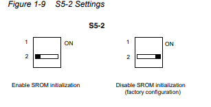
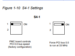
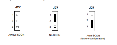
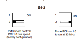
Jumpers on the CPUM and IOCN cards are used to configure the required operation of serial and Ethernet
interfaces and connectors. Refer to the VM600 machinery protection system (MPS) hardware manual for
further information.
System communications
Internal : VME bus interface (A24 / D16 master mode) for communication
with protection cards (MPC4 and AMC8) via VM600 rack
backplane
External : System communication interfaces (serial and Ethernet) for
communication with VM600 MPSx software running on an external
computer.
See Communication interfaces – serial on page 6 and
Communication interfaces – Ethernet on page 7.
External communication links/connections
• Connection to a computer/network : A serial communication interface (RS232 on CPUM card) can be
used for connections/communications between a CPUM/IOCN
card pair and a computer/network, using a standard serial cable.
See Communication interfaces – serial on page 6 and Connectors
on page 10.
An Ethernet communication interface (NET on CPUM card or 1 on
IOCN card) can be used for connections/communications
between a CPUM/IOCN card pair and a computer/network, using
standard cabling.
See Communication interfaces – Ethernet on page 7 and
Connectors on page 10.
• Connection to a fieldbus
(third-party system)
: A serial fieldbus communication interface (RS on IOCN card) can
be used for connections/communications between a CPUM/IOCN
card pair and serial-based fieldbuses (Modbus RTU).
See Communication interfaces – serial on page 6 and Connectors
on page 10.
An Ethernet fieldbus communication interface (NET on CPUM card
or 1 on IOCN card, or 2 on IOCN card) can be used for
connections/communications between a CPUM/IOCN
card pair and Ethernet-based fieldbuses (Modbus TCP).
See Communication interfaces – Ethernet on page 7 and
Connectors on page 10.
• VM600 MPSx software : Used for the configuration and operation of MPC4/IOC4T and
AMC8/IOC8T card pairs (using the CPUM/IOCN card pair as a
communications gateway)
• VibroSight® software : Used for the configuration of CPUM cards
Configuration
CPUM/IOCN card pair : Software configurable via Ethernet or serial, using a computer
running the VM600 MPSx and CPUM Configurator software.
Note: Serial (RS-232 / RS-422 / RS-485) line configuration and
Ethernet port to connector routing is determined by jumpers on the
CPUM and IOCN cards.
S
Time synchronisation
Time reference for CPUM : Network time protocol (NTP) server or
CPUM’s internal real-time clock (RTC) with battery backup
Protocol used between VM600 cards
and host computer
: Network time protocol (NTP)
Note: When VM600 system event and/or measurement event logging is used, the time and date must be
configured for the CPUM in order for the timestamps in the event log files to be correct.
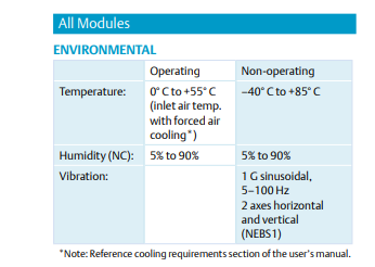
Environmental
Operating
• Temperature : −20 to 65°C (−4 to 149°F)
• Humidity : 0 to 90% relative humidity, non-condensing
Storage
• Temperature : −25 to 80°C (−13 to 176°F)
• Humidity : 0 to 90% relative humidity, non-condensing
Approvals
Conformity : CE marking, European Union (EU) declaration of conformity.
EAC marking, Eurasian Customs Union (EACU) certificate/
declaration of conformity.
Electromagnetic compatibility : TR CU 020/2011
Electrical safety : TR CU 004/2011
Environmental management : RoHS compliant
Russian federal agency for technical
regulation and metrology (Rosstandart)
: Pattern approval certificate CH.C.28.004.A N° 60224,
dated 11.11.2015
Power supply (to CPUM/IOCN)
Source : VM600 rack power supply
Voltage : 5 VDC
Power consumption
• CPUM : <10 W
• IOCN : <2 W
Total power consumption
(CPUM/IOCN card pair)
: ≤12 W
Control inputs (buttons)
CPUM
ALARM RESET : Used to reset all latched alarms (and associated relays) for all
protection cards in the VM600 rack (MPC4/IOC4T and AMC8/
IOC8T)
OUT+ and OUT− : Used to select a measurement channel for the currently selected
protection card (slot)
SLOT+ and SLOT− : Used to select a slot (protection card) in the VM600 rack
Note: OUT and SLOT button combinations are also used to enable
or disable VM600 rack (CPUM) security, that is, limit the VM600 MPSx
software to “read only” operations.
S
Status indicators (LEDs)
CPUM
DIAG : Green LED used to indicate the status of the CPUM card: off,
normal operation and status of VM600 MPS rack (CPUM) security
OK : Green LED used to indicate the status of the OK system check
(sensor OK link check) for the currently selected measurement
channel
A
(Alert)
: Yellow LED used to indicate the status of the alarm monitoring (Alert
or Alert−) for the currently selected measurement channel
D
(Danger)
: Red LED used to indicate the status of the alarm monitoring
(Danger or Danger−) for the currently selected measurement
channel
Note: In addition to the LED indicators, a front-panel display is fitted to all versions of the CPUM card.
Connectors
CPUM
• NET : 8P8C (RJ45), female.
Used for the primary Ethernet connection.
• RS232 : DE-9 (9-pin D-sub), female
Used for the primary serial connection.
IOCN
• RS : 6P6C (RJ12/RJ25), female.
Used for the secondary serial connection.
• A : Two 6P6C (RJ12/RJ25), female.
Used for additional serial connections (requires the optional serial
communications module).
• B : Two 6P6C (RJ12/RJ25), female.
Used for additional serial connections (requires the optional serial
communications module).
• 1 : 8P8C (RJ45), female.
Can be used for the primary Ethernet connection (instead of the
CPUM connector (NET)).
• 2 : 8P8C (RJ45), female.
Used for the secondary Ethernet connection.
Physical
CPUM
• Height : 6U (262 mm, 10.3 in)
• Width : 40 mm (1.6 in)
• Depth : 187 mm (7.4 in)
• Weight : 0.40 kg (0.88 lb) approx.
IOCN
• Height : 6U (262 mm, 10.3 in)
• Width : 20 mm (0.8 in)
• Depth : 125 mm (4.9 in)
• Weight : 0.25 kg (0.55 lb) approx.
S
ORDERING INFORMATION
To order please specify
Type Designation Ordering number (PNR)
CPUM Different versions of the VM600 modular CPU card:
– Ethernet redundant
Modular CPU card with a CPU module that supports two
Ethernet interfaces and two serial interfaces.
This CPUM supports Ethernet interfaces on the front panel
(CPUM) and the rear panel (IOCN), a serial interface (RS-232)
on the front panel (CPUM) and a serial interface (isolated
RS-232/RS-485) on the rear panel (IOCN).
200-595-0Ss-33h
(601-003-000-VVV3610-1CC-CCC
when pre-configured See notes)
– Ethernet redundant varnished
Same as the (standard) Ethernet redundant version, with a
conformal coating for additional environmental protection.
200-595-0Ss-33hl
(601-003-000-VVV3V610-1CC-CCC
when pre-configured See notes)
– Serial redundant
Modular CPU card with a CPU module that supports two
Ethernet interfaces and two serial interfaces, and a serial
communications module that supports additional serial
interfaces.
This CPUM supports Ethernet interfaces on the front panel
(CPUM) and the rear panel (IOCN), a serial interface (RS-232)
on the front panel (CPUM) and a serial interface (isolated
RS-232/RS-485) on the rear panel (IOCN). It also supports two
additional serial interfaces
(RS-422/RS-485) on the rear panel (IOCN).
200-595-0Ss-53h
(601-003-000-VVV5610-1CC-CCC
when pre-configured See notes)
IOCN Different versions of the input/output card for the CPUM:
– Ethernet redundant 200-566-000-1Hh
– Ethernet redundant varnished
Same as the (standard) Ethernet redundant version, with a
conformal coating for additional environmental protection.
200-566-000-1HhL
Notes
Different versions of the CPUM card can be supplied pre-configured with different configurations, as denoted by the 9-digit code in
the ordering number (610-1CC-CCC).
“1CC-CCC” represents the different configurations that can be used by a finished product. For example, 610-100-000 corresponds
to the ‘standard’ configuration that is uploaded to a CPUM card (200-595-0Ss-HHh), if no other configuration is specified. For
information on other configurations. Contact your local Meggitt representative or Meggitt SA for further information.
“Ss” represents the firmware (embedded software) version and “Hh” the hardware version of a card. “S/H” increments for major
modifications that can affect product interchangeability and “s/h” increments for minor modifications that have no effect on
interchangeability.
“VVV” represents the different firmware (embedded software) versions and hardware versions that can be used by a
finished produc
RELATED PRODUCTS
ABE04x VM600 system racks : Refer to corresponding data sheet
CPUR and IOCR VM600 rack controller and communications
interface card pair
Note: With rack controller redundancy and
support for Modbus RTU/TCP
: Refer to corresponding data sheet
CPUR2 and IOCR2 VM600 rack controller and communications
interface card pair
Note: With mathematical processing of
fieldbus data and support for Modbus TCP
and PROFIBUS
: Refer to corresponding data sheet
AMC8 and IOC8T VM600 analog monitoring card and
input/output card
: Refer to corresponding data sheet
MPC4 and IOC4T VM600 machinery protection card and
input/output card
: Refer to corresponding data sheets
RLC16 VM600 relay card : Refer to corresponding data sheet
Meggitt (Meggitt PLC) is a leading international engineering company, headquartered in England, that designs and delivers high-performance
components and subsystems for aerospace, defence and selected energy markets. Meggitt comprises four customer-aligned divisions:
Airframe Systems, Engine Systems, Energy & Equipment and Services & Support.
The Energy & Equipment division includes the Energy Sensing and Controls product group that specialises in sensing and monitoring solutions for a
broad range of energy infrastructure, and control valves for industrial gas turbines, primarily for the Power Generation, Oil & Gas and Services markets.
Energy & Equipment is headquartered in Switzerland (Meggitt SA) and incorporates the Vibro-Meter® product line, which has over 65 years of sensor
and systems expertise and is trusted by original equipment manufacturers (OEMs) globally.
All information in this document, such as descriptions, specifications, drawings, recommendations and other statements, is believed to be
reliable and is stated in good faith as being approximately correct, but is not binding on Meggitt (Meggitt SA) unless expressly agreed in
writing. Before acquiring and/or using this product, you must evaluate it and determine if it is suitable for your intended application. You
should also check our website at www.meggittsensing.com/energy for any updates to data sheets, certificates, product drawings, user
manuals, service bulletins and/or other instructions affecting the product.
Unless otherwise expressly agreed in writing with Meggitt SA, you assume all risks and liability associated with use of the product. Any
recommendations and advice given without charge, whilst given in good faith, are not binding on Meggitt SA. Meggitt (Meggitt SA) takes
no responsibility for any statements related to the product which are not contained in a current Meggitt SA publication, nor for any
statements contained in extracts, summaries, translations or any other documents not authored and produced by Meggitt SA.
The certifications and warranties applicable to the products supplied by Meggitt SA are valid only for new products purchased directly from
Meggitt SA or from an authorised distributor of Meggitt SA.
In this publication, a dot (.) is used as the decimal separator and thousands are separated by thin spaces. Example: 12345.67890.
Copyright© 2019 Meggitt SA. All rights reserved. The information contained in this document is subject to change without prior notice.