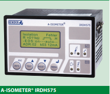
Description
The IRDH575 monitors for ground faults in ungrounded AC (20 – 760 V, single- and threephase) and DC (20 – 575 V) by measuring the system’s insulation resistance. Systems with
extensive power conversion devices, such as rectifiers and variable frequency drives, are
supported by the IRDH575. The IRDH575 is able to detect ground faults in ungrounded
systems before leakage current may even be present.
When combined with EDS4… ground fault location devices and the appropriate current
transformers, the IRDH575 becomes a controller for a ground fault location system.
Function: Ground fault detection
When the insulation resistance from system to ground falls below the set response value,
the alarm relays switch and the alarm LEDs activate. Two separately adjustable alarm
contacts can be set to a prewarning and main warning alarm. The measured value is indicated on the LCD display or on an externally connected meter. If the device is set to nonlatching mode, the alarms will clear when the ground fault clears. If the device is set to
latching mode, the alarms will not reset until the device is reset manually or the supply
voltage is lost. An external and internal test/reset can be activated remotely or on the device. A comprehensive INFO menu key displays additional information such as the current leakage capacitance and device settings.
The IRDH575 continuously monitors the equipment ground connection and line connections to ensure proper operation. The device’s easy-to-use onboard menu manages all
settings via the detailed LCD screen.
Function: Ground fault location
When a ground fault is detected, the EDS ground fault location system is activated (this
feature can be set to require a manual start as well). Each channel of the EDS location device is connected to a particular branch circuit. The IRDH575 begins transmitting a pulsed
signal. This signal will travel through the channel of the EDS with the ground fault back
to the IRDH575. If the pulse travels back to the IRDH575, the channel with the ground
fault will display on both the IRDH575 and the EDS device.
In addition, an optional EDS30… portable ground fault location system can be used to follow the pulse travelling to the source of the ground fault.
Additional functions
99 timestamped alarm messages may be stored in the non-volatile memory of the
IRDH575. The device also includes standby contacts when several A-ISOMETER® detectors
are operating in coupled ungrounded systems.
Two-way data communication is carried out between devices via an RS-485 interface.
This interface can be connected to a BENDER protocol converter to exchange data across
other protocols, such as Ethernet, MODBUS, or PROFIBUS.
A 0/4 – 20 mA output can be connected to an external meter or higher-level control system, such as a PLC.
System design
Each isolated system requires one IRDH575 for ground fault detection and location control. Up to 90 EDS46… devices can be interconnected to the IRDH575. Each EDS device
can monitor up to 12 separate channels. An optional EDS30…. portable ground fault location system can be used in conjunction with the IRDH575/EDS46… system.
Features
• Universal application in 3(N)AC, AC/DC
and DC ungrounded systems 20…575
V/340…760 V
• Response range 1 kΩ…10 MΩ
• Info key for the indication of various
parameters and the system leakage
capacitance
• Comprehensive self-monitoring function
including system fault alarm relay
• Internal/external test and reset button
• Two separate alarm relays, operating
normally energized or normally de-energized
• Backlit LCD display
• RS-485 interface
• Data memory, system disconnection and
0/4…20mA current output
• Extendable to ground fault
location system for 1080 circuits
• Adjustable test current for ground fault
location
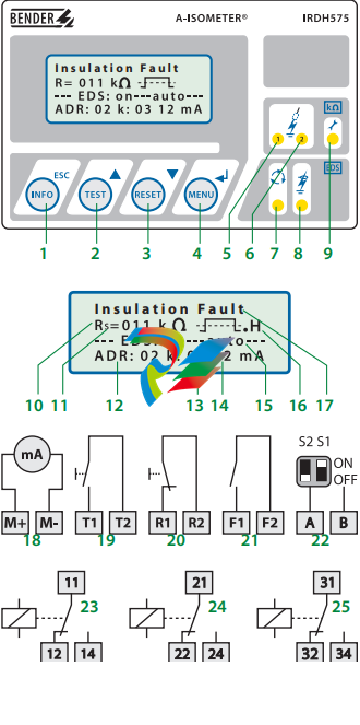
1 – INFO key: Displays pertinent system information
ESC key: Goes back a step inside device’s menu
2 – TEST button: Activates self-test
Arrow up key: Scrolls down inside device’s menu
3 – RESET button: Resets device
Arrow down key: Scrolls down inside device’s menu
4 – MENU key: Activates device’s internal menu
Enter key: Confirm change inside device’s menu
5 – Alarm LED 1 lights: Insulation fault, warning level reached
6 – Alarm LED 2 lights: Insulation fault, alarm level reached
7 – EDS LED lights: Indicates ground fault location is active
8 – EDS alarm LED lights: Indicates EDS ground fault location device is in alarm
9 – LED lights: Indicates system fault alarm
10 – Real-time measurement of insulation resistance in kΩ
11 – Additional information – “s” displayed when device has begin a
new measurement
12 – Active when EDS4… is connected and in alarm; indicates
address of EDS4… in alarm
13 – Active when EDS4… is connected and in alarm; indicates
channel of EDS4… in alarm
14 – Active when EDS4… is connected and in alarm; indicates
strength of test signal detected by the channel in alarm (mea
sured in mA or µA)
15 – Active when EDS4… is connected. Displays mode of operation
for ground fault location system. AUTO indicates location system is activated automatically when IRDH575 goes into alarm.
System may also be set manually on or off.
16 – Polarity of the test current pulse. Point = valid BMS traffic,
H = A new entry has been made in the history.
17 – Text indicating state of device
18 – Analog output: 0…20 mA or 4…20 mA (selectable)
19 – External test button (N/D contact)
20 – External reset button (N/E contact or wire jumper). When the
terminals are open, the device will reset automatically.
21 – STANDBY contacts. When the contacts are closed, the device
is forced into standby mode and will not send out a measurement signal.
22 – RS-485 termination (120 Ω) with micro switch S1 and connection
BMS bus; S1 = ON = BMS bus terminated, S2 = unassigned
23 – Alarm relay: Alarm 1 (A-ISOMETER®)
24 – Alarm relay: Alarm 2 (A-ISOMETER®)
25 – Alarm relay: System fault and EDS alarm (Adr.:1)
Example: IRDH575 with EDS460 (main circuits)
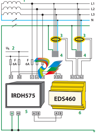
EDS460 system with IRDH575, EDS460 and measuring current
transformers W… in a three-phase AC system
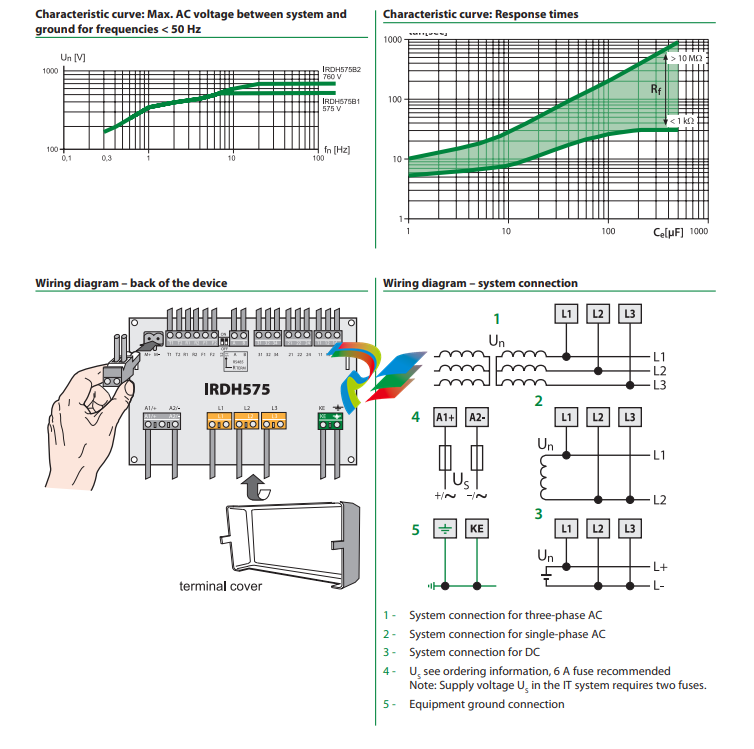
1 – 3AC/3NAC/AC 20…575 V
2 – US
see ordering information, 6 A fuse recommended.
3 – Current transformers, W series
4 – Loads
5 – A-ISOMETER® IRDH575
6 – Ground fault location device EDS460
Example: IRDH575 with EDS461 (control circuits)
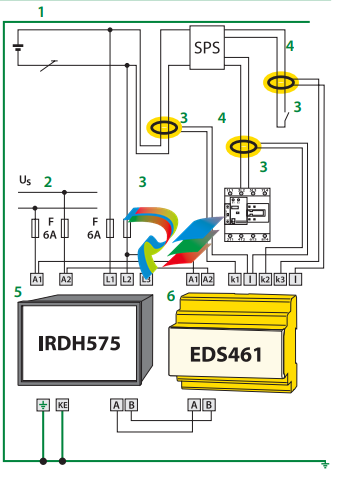
1 – DC 20 V…308 V
2 – US
see ordering information, 6 A fuse recommended.
3 – Current transformers, W…/8000 series
4 – Load PLC
5 – A-ISOMETER® IRDH575
6 – Ground fault location device EDS461
Design of an EDS461 system
The above example shows an EDS461 device being fed by a PLC
in a DC system. Using an EDS461 device is recommended for PLC
inputs due to the sensitivity required.
Leave a comment
Your email address will not be published. Required fields are marked *