Product description
The AC / DC sensitive residual current monitor RCMA475LY is designed for monitoring earthed
power supply systems (TN and TT systems) where DC fault currents or residual currents continuously greater than zero may occur. These are in particular loads containing six-pulse
rectifiers or one way rectifiers with smoothing, such as converters, battery chargers, construction site equipment with frequency-controlled drives.
The prewarning stage (50 % of the set response value IΔn1) allow to distinguish between
prewarning and alarm. Since the values are measured with measuring current transformers,
the device is nearly independent of the load current and the nominal voltage of the system.
Application
• AC / DC sensitive residual current monitoring in earthed two, three or four conductor
systems.
• AC / DC sensitive current monitoring of single conductors de-energized under normal
conditions (e. g. N and PE conductors).
• Variable-speed drives
• Uninterruptible power supply systems (UPS)
Device features
• Internal measuring current transformer
ø 18 mm
• Two response values:
Alarm IΔn1: 30 mA…500 mA (0…700 Hz)
Prewarning IΔn2: 50 % / 100 % of IΔn1
• Adjustable response delay 0…10 s
(prewarning 0 / 1 s)
• Two separately adjustable alarm relays
with one changeover contact each
• N / O or N / C operation
• Fault memory
• Combined TEST and RESET button
• Connection external TEST and RESET
button
• LED bar graph indicator IΔn 0…100 %
• Connection external measuring instrument IΔn 0…100 %
• Sealable transparent cover
• Separate supply voltage
• Type B acc. to IEC 60755
Function
Residual current monitoring takes place via an internal measuring current transformer. When
the current respectively the residual current exceeds the set response value, the alarm LED
lights and the associated alarm relay switches when the set response delay has elapsed.
The alarm messages are stored. The fault memory can be reset by pressing the RESET button.
The device function can be tested using the TEST button.
The currently measured value in per cent related to the set response value is indicated on
the LED bar graph indicator.
Wiring diagram – system connection, external connections
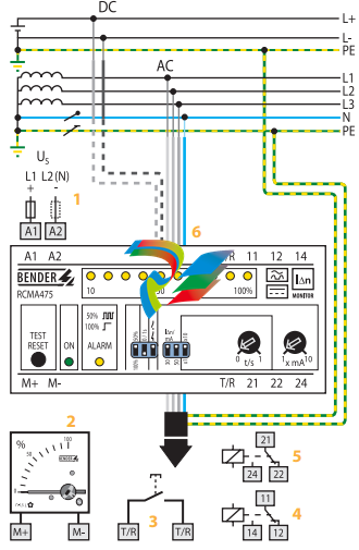
1 – Supply voltage US (see ordering information), a 6 A fuse recommended for line protection
2 – External measuring instrument
3 – External TEST and RESET button
4 – Alarm relay (alarm): switches when the fault current exceeds
the response value IΔn1.
5 – Alarm relay (prewarning): switches when the fault current
exceeds 50 % or 100 % of the response value IΔn1.
6 – Internal measuring current transformer
Do not route the PE conductor through the measuring current
transformer !
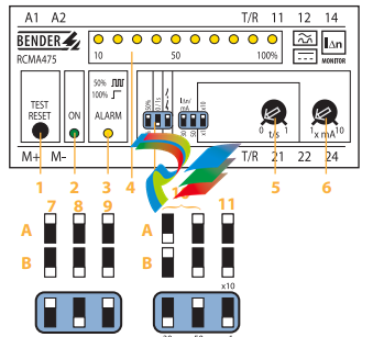
1 – Combined TEST and RESET button: short-time pressing (< 1 s)
= RESET, long-time pressing (> 2 s) = TEST.
2 – Power On LED: lights when the device is in operation and flashes
when the measuring range is exceeded.
3 – Alarm LED: lights when the fault current exceeds the set response value and flashes when 50 % of the set response value
are reached.
4 – LED bar graph indicator, shows the measuring value in per
cent related to the preset response value.
5 – Potentiometer for setting the response delay (0…1 s)
6 – Potentiometer for setting the response value (x 1…10 mA)
Setting of the DIP switches (white = switch position)
7 – Contact 21-22-24 (prewarning)
A – at 50 % of IΔn1
B – at 100 % of IΔn1
8 – Response delay prewarning
A – Delay 1 s
B – Delay 0 s
9 – Alarm relay
A – N / O operation
B – N / C operation
10 – Response range
A – 30 mA x 1…10 B – 50 mA
11 – Response delay
A – Setting value t
/s x10
B – Setting value t
/s x1
Technical data residual current monitor RCMA475LY
Insulation coordination acc. to IEC 60664-1
Rated insulation voltage AC 250 V
Rated impulse voltage / pollution degree 4 kV / 3
Voltage ranges
Supply voltage US see ordering information
Operating range of US 0.85…1.1 x US
Frequency range of US DC / 50…60 Hz
Power consumption ≤ 3.5 VA
Measuring circuit/response values
Internal measuring current transformer ø 18 mm
Operating characteristic acc. to IEC 60755 Type B
Rated residual operating current IΔn2 (prewarning) 50 / 100 % of IΔn1
Response delay tv 0 / 1 s
Rated residual operating current IΔn1 (alarm) 30…500 mA
Response delay tv, adjustable 0…10 s
Rated frequency 0…700 Hz
Relative percentage error 0…- 25 %
Hysteresis approx. 25 % of the response value
Response time tan at IΔn1 = 1 x IΔn1 / 2 (tv = 0 s) < 70 ms
Response time tan at IΔn1 = 5 x IΔn1 / 2 (tv = 0 s) < 40 ms
Displays
LED bar graph indicator 0…100 %
LEDs Power On, prewarning, alarm
Inputs / outputs
TEST and RESET button internal / external
Cable length external TEST and RESET button ≤ 10 m
Current source for external measuring instrument 0…100 % DC 0…400 μA
Load ≤ 12.5 kΩ
Switching elements
Number of switching elements 2 x 1 changeover contact
Operating principle, adjustable N / C operation / N / O operation
Electrical endurance, number of cycles 12000
Rated contact voltage AC 250 V / DC 300 V
Limited making capacity AC / DC 5 A
Breaking capacity 2 A, AC 230 V, cos phi = 0,4
0.2 A, DC 220 V, L / R = 0.04 s
Fault memory ON
General data
EMC immunity acc. to EN 61543
EMC emission acc. to EN 61000-6-4
Shock resistance IEC 60068-2-27 (during operation) 15 g / 11 ms
Bumping IEC 60068-2-29 (during transport) 40 g / 6 ms
Vibration resistance IEC 60068-2-6 (during operation) 1 g / 10…150 Hz
Vibration resistance IEC 60068-2-6 (during transport) 2 g / 10…150 Hz
Ambient temperature, during operation – 25 °C…+ 70 °C
Ambient temperature, when stored – 40 °C…+ 75 °C
Climatic category IEC 60721-3-3 3K5
Operating mode continuous operation
Mounting any position
Connection screw terminals
Connection properties
rigid / flexible 0.2…4 / 0.2…2.5 mm2
flexible with ferrules without / with plastic collar 0.25…2.5 mm2
Conductor sizes (AWG) 24…12
Protection class, internal components (IEC 60529) IP30
Protection class, terminals (IEC 60529) IP20
Type of enclosure X475
Enclosure material polycarbonate
Screw mounting 2 x M4
DIN rail mounting acc. to IEC 60715
Flammability class UL94V-0
Standards IEC 62020
Instruction leaflet BP404001
Weight ≤ 350 g
Accessories
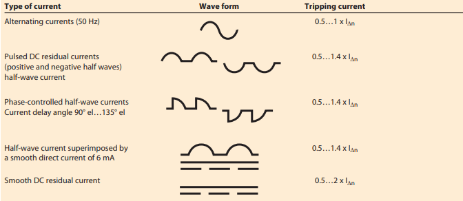
Conditions of operation according to IEC 62020, IEC 60755 amendment 2, Type B
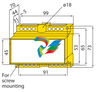
Dimension diagram X475
Dimensions in mm

Leave a comment
Your email address will not be published. Required fields are marked *