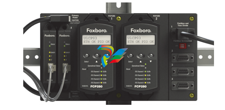
The fault-tolerant version of the FCP280 consists of
two processor modules. These modules are installed
in adjacent FCP280 slots in a baseplate for high
speed communication between the modules.
The FCP280 accepts four PIO channels (that is, four
separate HDLC fieldbuses) via the four Fieldbus ports
on its baseplate. These four Fieldbuses are referred
to collectively as the “Expanded fieldbus.” For a
description of the FCP280 baseplates, refer to DIN
Rail Mounted Modular Baseplates
(PSS 21H-2W6 B4).
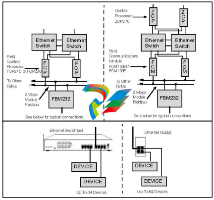
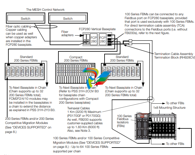
The number of FBMs which an FCP280 can support
varies depending on the types of FBMs used:
200 Series FBMs exclusively used with FCP280 –
Each Fieldbus port on the FCP280 baseplate can
connect to a baseplate chain with up to 32
Compact or standard 200 Series FBMs per chain
via the 2 Mbps HDLC fieldbus (up to 128
modules).
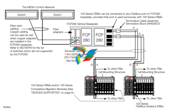
200 Series and 100 Series FBMs (dual baud
configurations) used with FCP280 – The FCP280
can support a total of 64 100 Series FBMs (Ymodule) or competitive devices (such as Foxboro
Evo System migration FBMs) in one or more
baseplate chains, with the remainder of the
FCP280’s 128 module limit being 200 Series
FBMs, depending on the Fieldbus loading of the
FCP280. For example, an FCP280 could support
64 100 Series FBMs and 64 200 Series FBMs (as
128 – 64 = 64). See Figure 2 and Figure 3 below.
NOTE
Certain competitive migration or supported
third-party modules such as DCS Migration
fieldbus Modules and Pepperl+Fuchs™ I/O
modules may increase this 128 module
maximum per FCP280. For the maximum
numbers of each of these migration/thirdparty modules supported by the FCP280,
refer to the supported migration products
books in Field Control Processor 280
(FCP280) User’s Guide (B0700FW).
When supporting 200 Series and 100 Series FBMs,
each Fieldbus port (PIO channel) is dedicated to
supporting either a 268 Kbps HDLC fieldbus (for
100 Series FBMs) or a 2 Mbps HDLC fieldbus (for
200 Series FBMs) – not both.
For connections to 100 Series FBMs over 60 m
(198 ft), an FBI200 pair is required to extend
communications up to 1830 m (6000 ft). See
Figure 2 below.
To connect a Fieldbus port to a 268 Kbps HDLC
fieldbus directly, the Fieldbus splitter (RH928CV)
provides a connector for any Fieldbus port on the
FCP280 baseplate, and two Termination Cable
Assembly (TCA) termination blocks for the twinaxial
cabling from the 100 Series FBMs.
The FCP280 can also communicate with serial and
Ethernet devices, such as PLCs, via Field Device
System Integrators. This allows you to connect to
new device interfaces without any changes to the
controller software.
To estimate the FCP280’s processor load, refer to
Field Control Processor 280 (FCP280) Sizing
Guidelines and Excel Workbook (B0700FY)
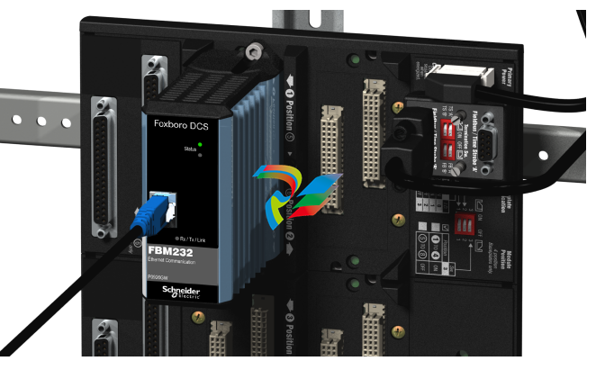
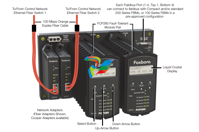
FIBER AND COPPER NETWORK ADAPTERS
FCP280 modules connect to a pair of fiber or copper
adapters (see Figure 4) which each connect to one
Ethernet switch in The Mesh control network. The
FCP280 baseplate passes inbound traffic from either
of the two switches to both FCP280s, and pass
outbound traffic from the primary FCP280 module to
either switch.
Figure 4. Fiber Optic and Copper Network Adapters
The fiber or copper adapters mount on the FCP280
baseplate as shown in Figure 1 on page 2. They
receive their power from the baseplate.
REMOTE MOUNTING
The FCP280 simplifies the Foxboro Evo Process
Automation System architecture, maintaining control
while only requiring housing (via field enclosures),
host workstations with Foxboro Evo Control Core
Services v9.0 or later, and Ethernet switches for
communication via The Mesh control network
architecture, described in PSS 21H-7C2 B3.
The field-mounted FCP280 is an integral part of the
highly-distributed control network where controllers
are closely aligned to specific process units mounted
in close proximity to their I/O and the actual
equipment being controlled. Coordination between
process units takes place via a fiber optic 100 Mbps
Ethernet network.
The FCP280 and its network adapters are packaged
in a rugged, die cast aluminum housing that does not
require venting due to its efficient design. The
FCP280 and its network adapters are CE certified,
and it can be mounted without expensive special
cabinets to prevent electronic emissions. The
FCP280, network adapters, and baseplate can be
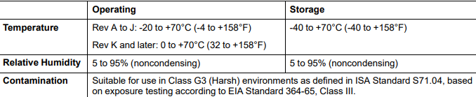
mounted in Class G3 harsh environments.
ENHANCED RELIABILITY (FAULTTOLERANCE)
The unique and patented fault-tolerant operation of
the FCP280 improves reliability relative to legacy
process controllers. The fault-tolerant version of the
FCP280 consists of two modules operating in
parallel, with two Ethernet connections to The Mesh
control network. The two FCP280 modules, married
together as a fault-tolerant pair, provide continuous
operation of the controller in the event of virtually any
hardware failure occurring within one module of the
pair.
Both modules receive and process information
simultaneously, and faults are detected by the
modules themselves. One of the significant methods
of fault detection is comparison of communication
messages at the module external interfaces.
Messages only leave the FCP280 when both
FCP280s agree on the message being sent (bit for
bit match). Upon detection of a fault, self-diagnostics
are run by both modules to determine which module
is defective. The non-defective module then assumes
control without affecting normal system operations.
This fault-tolerant solution has the following major
advantages over controllers that are merely
redundant:
No bad messages are sent to the field or to
applications using controller data because no
message is allowed out of the controller unless
both modules match bit for bit on the message
being sent.
The secondary controller is synchronized with the
primary one, which ensures up to the moment
data in the event of a primary controller failure.
The secondary controller will have latent flaws
detected prior to any switchover because it is
performing exactly the same operations as the
primary controller.
UPGRADE OPTIONS
Multiple options are available for replacing existing
control processors with the FCP280. A fault-tolerant
FCP280 may replace a fault-tolerant FCP270 or
ZCP270. It may import the CP database from the
CP270 it is replacing, for compatibility and minimal
configuration time.
As well the FCP280 provides an increase in
performance and block processing capacity over the
CP270s. When replacing FCP270s, the FCP280
eliminates the need for FEM100 hardware.
For ease of replacement, the fault-tolerant or nonfault-tolerant FCP280 in its baseplate has the same
dimensions as the fault-tolerant or non-fault-tolerant
FCP270 in its baseplate.
Cabling the 100 Series FBMs or Migration products
to an FCP280 baseplate consists of extending the
remote 268 Kbps fieldbus between enclosures. This
is accomplished using termination cable assemblies
(TCAs) and Fieldbus Isolators (FBIs) to provide
connections between primary and extended fieldbus
segments.
The optional FBI200 can extend the 2 Mbps HDLC
fieldbus between 200 Series FBMs from 60 m (198 ft)
up to 305 m (1000 ft). As well, it can extend the
268 Kbps HDLC fieldbus between 100 Series FBMs
from 60 m (198 ft) up to 1830 m (6000 ft).
As with earlier generations of control processors, up
to 64 100 Series FBMs (including expansion
modules) attach to Fieldbus ports through Fieldbus
Isolators. (Up to 24 100 Series FBMs, excluding
expansion modules, can connect to each isolator.
However, the expansion modules are considered
100 Series FBMs in this “64 100 Series FBMs”
maximum discussed in this PSS.)
Available upgrade scenarios are available in Field
Control Processor 280 (FCP280) User’s Guide
(B0700FW).
FBI200 FIELDBUS ISOLATOR/FILTER
The FBI200 Fieldbus Isolator/Filter extends the length
of the 268 Kbps module Fieldbus from the FCP280
to 100 Series FBMs and similar competitive migration
modules up to 1830 m (6000 ft) over a twinaxial
Fieldbus cable. See Figure 2 on page 4.
It can also extend the 2 Mbps HDLC fieldbus to
200 Series FBMs up to 305 m (1000 ft).
For more information on the FBI200, refer to FBI200
Fieldbus Isolator/Filter (PSS 21H-2Y18 B4).
FIRMWARE UPGRADES WHILE ON-LINE
For fault-tolerant FCP280 modules, on-line image
upgrade replaces the executable image (operating
system) of a running FCP280 with a newer image
without having to shut down the equipment being
controlled by the FCP280.
TIME SYNCHRONIZATION, SOE, TDR/TDA
The Foxboro Evo Process Automation System
supports time synchronization using either an
externally maintained optional source of Universal
Coordinated Time (UTC) from GPS satellites or an
internal source using proprietary software. FCP280s
that receive time updates via the external time source
synchronize their FBMs to 1 ms. For more
information on time synchronization, refer to Time
Synchronization Overview (PSS 21S-1C2 B3).
Time stamping is used for alarm messages, values
sent to the historian, and the Sequence Of Events
(SOE) and Transient Data Recorder (TDR), and
Transient Data Analyzer (TDA) features.
SOE data are discrete points that are time stamped at the FBM, optionally to 1 ms, and sent to the workstation on a change basis. TDR/TDA data are analog or digital points that are time stamped at the FBM and sent to the workstation every 10 ms. These features are supported by client software in the workstation. For information on this new software, refer to Field Control Processor 280 (FCP280) Integrated Control Software (PSS 31S-3B3 B3). SOFTWARE CONTROL FEATURES The FCP280 performs regulatory, logic, timing, and sequential control, as well as data acquisition, alarm detection, and alarm notification. Process variables are controlled using time-proven algorithms (mathematical computations performing specific functions). The algorithms are contained in functional control blocks, which on-site process engineers configure to implement the desired control strategies. The versatility of the algorithms, coupled with the variety of FBMs available, provides control capabilities suited to a broad range of process applications. Control strategies ranging from simple feedback and cascade loops to highly sophisticated feedforward, nonlinear, and complex characterization control schemes are readily implemented. The FCP280 also supports the following features: Setting and reading the FCP280 letterbug via the buttons on the faceplate Alarm enhancements to function blocks: re-alarming on changes to alarm priority, re-alarming based upon a configurable time delay deadband, and alarm suppression based upon time Optional UTC external time synchronization Improved controller performance Optional self-hosting mode allows the FCP280 to start up and run, executing its configured control scheme using the checkpoint file stored in flash memory. This allows the FCP280 to boot itself with a valid control database even if its host workstation is not present. Support for high speed capabilities such as ladder logic, Motor Driven Actuator Controller (MDACT), and Distributed Proportional Integral Derivative functionality (DPIDA) DEVICES SUPPORTED The FCP280 supports the following devices on the 2 Mbps fieldbus: All Compact and standard 200 Series FBMs (FBM201, FBM202, and so forth), which can support many types of intelligent field devices, including those on FOUNDATION fieldbus, PROFIBUS, HART, and DeviceNet networks Field Device Systems Integrator (FDSI) modules Intrinsically Safe I/O Subsystem (ISCM) – refer to PSS 21H-2Y6 B4). DCS Migration fieldbus Modules for Siemens APACS+ Systems DCS Migration fieldbus Modules for Westinghouse WDPF® Systems DCS Migration fieldbus Modules for Fisher’s PROVOX® Series 20 Migration with HART DCS Migration fieldbus Modules for Honeywell® TDC 2000 Systems with HART. The FCP280 supports the following devices on the 268 Kbps fieldbus: 100 Series FBMs (FBM01, FBM02, and so forth) SPECTRUM™ Migration Integrators SPEC 200™ Control Integrators SPEC 200 MICRO™ Control Integrators SPEC 200 CCM Control Integrators
The fault-tolerant version of the FCP280 consists of
two processor modules. These modules are installed
in adjacent FCP280 slots in a baseplate for high
speed communication between the modules.
The FCP280 accepts four PIO channels (that is, four
separate HDLC fieldbuses) via the four Fieldbus ports
on its baseplate. These four Fieldbuses are referred
to collectively as the “Expanded fieldbus.” For a
description of the FCP280 baseplates, refer to DIN
Rail Mounted Modular Baseplates
(PSS 21H-2W6 B4).
The number of FBMs which an FCP280 can support
varies depending on the types of FBMs used:
200 Series FBMs exclusively used with FCP280 –
Each Fieldbus port on the FCP280 baseplate can
connect to a baseplate chain with up to 32
Compact or standard 200 Series FBMs per chain
via the 2 Mbps HDLC fieldbus (up to 128
modules).
200 Series and 100 Series FBMs (dual baud
configurations) used with FCP280 – The FCP280
can support a total of 64 100 Series FBMs (Ymodule) or competitive devices (such as Foxboro
Evo System migration FBMs) in one or more
baseplate chains, with the remainder of the
FCP280’s 128 module limit being 200 Series
FBMs, depending on the Fieldbus loading of the
FCP280. For example, an FCP280 could support
64 100 Series FBMs and 64 200 Series FBMs (as
128 – 64 = 64). See Figure 2 and Figure 3 below.
NOTE
Certain competitive migration or supported
third-party modules such as DCS Migration
fieldbus Modules and Pepperl+Fuchs™ I/O
modules may increase this 128 module
maximum per FCP280. For the maximum
numbers of each of these migration/thirdparty modules supported by the FCP280,
refer to the supported migration products
books in Field Control Processor 280
(FCP280) User’s Guide (B0700FW).
When supporting 200 Series and 100 Series FBMs,
each Fieldbus port (PIO channel) is dedicated to
supporting either a 268 Kbps HDLC fieldbus (for
100 Series FBMs) or a 2 Mbps HDLC fieldbus (for
200 Series FBMs) – not both.
For connections to 100 Series FBMs over 60 m
(198 ft), an FBI200 pair is required to extend
communications up to 1830 m (6000 ft). See
Figure 2 below.
To connect a Fieldbus port to a 268 Kbps HDLC
fieldbus directly, the Fieldbus splitter (RH928CV)
provides a connector for any Fieldbus port on the
FCP280 baseplate, and two Termination Cable
Assembly (TCA) termination blocks for the twinaxial
cabling from the 100 Series FBMs.
The FCP280 can also communicate with serial and
Ethernet devices, such as PLCs, via Field Device
System Integrators. This allows you to connect to
new device interfaces without any changes to the
controller software.
To estimate the FCP280’s processor load, refer to
Field Control Processor 280 (FCP280) Sizing
Guidelines and Excel Workbook (B0700FY)
FIBER AND COPPER NETWORK ADAPTERS
FCP280 modules connect to a pair of fiber or copper
adapters (see Figure 4) which each connect to one
Ethernet switch in The Mesh control network. The
FCP280 baseplate passes inbound traffic from either
of the two switches to both FCP280s, and pass
outbound traffic from the primary FCP280 module to
either switch.
Figure 4. Fiber Optic and Copper Network Adapters
The fiber or copper adapters mount on the FCP280
baseplate as shown in Figure 1 on page 2. They
receive their power from the baseplate.
REMOTE MOUNTING
The FCP280 simplifies the Foxboro Evo Process
Automation System architecture, maintaining control
while only requiring housing (via field enclosures),
host workstations with Foxboro Evo Control Core
Services v9.0 or later, and Ethernet switches for
communication via The Mesh control network
architecture, described in PSS 21H-7C2 B3.
The field-mounted FCP280 is an integral part of the
highly-distributed control network where controllers
are closely aligned to specific process units mounted
in close proximity to their I/O and the actual
equipment being controlled. Coordination between
process units takes place via a fiber optic 100 Mbps
Ethernet network.
The FCP280 and its network adapters are packaged
in a rugged, die cast aluminum housing that does not
require venting due to its efficient design. The
FCP280 and its network adapters are CE certified,
and it can be mounted without expensive special
cabinets to prevent electronic emissions. The
FCP280, network adapters, and baseplate can be
mounted in Class G3 harsh environments.
ENHANCED RELIABILITY (FAULTTOLERANCE)
The unique and patented fault-tolerant operation of
the FCP280 improves reliability relative to legacy
process controllers. The fault-tolerant version of the
FCP280 consists of two modules operating in
parallel, with two Ethernet connections to The Mesh
control network. The two FCP280 modules, married
together as a fault-tolerant pair, provide continuous
operation of the controller in the event of virtually any
hardware failure occurring within one module of the
pair.
Both modules receive and process information
simultaneously, and faults are detected by the
modules themselves. One of the significant methods
of fault detection is comparison of communication
messages at the module external interfaces.
Messages only leave the FCP280 when both
FCP280s agree on the message being sent (bit for
bit match). Upon detection of a fault, self-diagnostics
are run by both modules to determine which module
is defective. The non-defective module then assumes
control without affecting normal system operations.
This fault-tolerant solution has the following major
advantages over controllers that are merely
redundant:
No bad messages are sent to the field or to
applications using controller data because no
message is allowed out of the controller unless
both modules match bit for bit on the message
being sent.
The secondary controller is synchronized with the
primary one, which ensures up to the moment
data in the event of a primary controller failure.
The secondary controller will have latent flaws
detected prior to any switchover because it is
performing exactly the same operations as the
primary controller.
UPGRADE OPTIONS
Multiple options are available for replacing existing
control processors with the FCP280. A fault-tolerant
FCP280 may replace a fault-tolerant FCP270 or
ZCP270. It may import the CP database from the
CP270 it is replacing, for compatibility and minimal
configuration time.
As well the FCP280 provides an increase in
performance and block processing capacity over the
CP270s. When replacing FCP270s, the FCP280
eliminates the need for FEM100 hardware.
For ease of replacement, the fault-tolerant or nonfault-tolerant FCP280 in its baseplate has the same
dimensions as the fault-tolerant or non-fault-tolerant
FCP270 in its baseplate.
Cabling the 100 Series FBMs or Migration products
to an FCP280 baseplate consists of extending the
remote 268 Kbps fieldbus between enclosures. This
is accomplished using termination cable assemblies
(TCAs) and Fieldbus Isolators (FBIs) to provide
connections between primary and extended fieldbus
segments.
The optional FBI200 can extend the 2 Mbps HDLC
fieldbus between 200 Series FBMs from 60 m (198 ft)
up to 305 m (1000 ft). As well, it can extend the
268 Kbps HDLC fieldbus between 100 Series FBMs
from 60 m (198 ft) up to 1830 m (6000 ft).
As with earlier generations of control processors, up
to 64 100 Series FBMs (including expansion
modules) attach to Fieldbus ports through Fieldbus
Isolators. (Up to 24 100 Series FBMs, excluding
expansion modules, can connect to each isolator.
However, the expansion modules are considered
100 Series FBMs in this “64 100 Series FBMs”
maximum discussed in this PSS.)
Available upgrade scenarios are available in Field
Control Processor 280 (FCP280) User’s Guide
(B0700FW).
FBI200 FIELDBUS ISOLATOR/FILTER
The FBI200 Fieldbus Isolator/Filter extends the length
of the 268 Kbps module Fieldbus from the FCP280
to 100 Series FBMs and similar competitive migration
modules up to 1830 m (6000 ft) over a twinaxial
Fieldbus cable. See Figure 2 on page 4.
It can also extend the 2 Mbps HDLC fieldbus to
200 Series FBMs up to 305 m (1000 ft).
For more information on the FBI200, refer to FBI200
Fieldbus Isolator/Filter (PSS 21H-2Y18 B4).
FIRMWARE UPGRADES WHILE ON-LINE
For fault-tolerant FCP280 modules, on-line image
upgrade replaces the executable image (operating
system) of a running FCP280 with a newer image
without having to shut down the equipment being
controlled by the FCP280.
TIME SYNCHRONIZATION, SOE, TDR/TDA
The Foxboro Evo Process Automation System
supports time synchronization using either an
externally maintained optional source of Universal
Coordinated Time (UTC) from GPS satellites or an
internal source using proprietary software. FCP280s
that receive time updates via the external time source
synchronize their FBMs to 1 ms. For more
information on time synchronization, refer to Time
Synchronization Overview (PSS 21S-1C2 B3).
Time stamping is used for alarm messages, values
sent to the historian, and the Sequence Of Events
(SOE) and Transient Data Recorder (TDR), and
Transient Data Analyzer (TDA) features.
SOE data are discrete points that are time stamped at the FBM, optionally to 1 ms, and sent to the workstation on a change basis. TDR/TDA data are analog or digital points that are time stamped at the FBM and sent to the workstation every 10 ms. These features are supported by client software in the workstation. For information on this new software, refer to Field Control Processor 280 (FCP280) Integrated Control Software (PSS 31S-3B3 B3). SOFTWARE CONTROL FEATURES The FCP280 performs regulatory, logic, timing, and sequential control, as well as data acquisition, alarm detection, and alarm notification. Process variables are controlled using time-proven algorithms (mathematical computations performing specific functions). The algorithms are contained in functional control blocks, which on-site process engineers configure to implement the desired control strategies. The versatility of the algorithms, coupled with the variety of FBMs available, provides control capabilities suited to a broad range of process applications. Control strategies ranging from simple feedback and cascade loops to highly sophisticated feedforward, nonlinear, and complex characterization control schemes are readily implemented. The FCP280 also supports the following features: Setting and reading the FCP280 letterbug via the buttons on the faceplate Alarm enhancements to function blocks: re-alarming on changes to alarm priority, re-alarming based upon a configurable time delay deadband, and alarm suppression based upon time Optional UTC external time synchronization Improved controller performance Optional self-hosting mode allows the FCP280 to start up and run, executing its configured control scheme using the checkpoint file stored in flash memory. This allows the FCP280 to boot itself with a valid control database even if its host workstation is not present. Support for high speed capabilities such as ladder logic, Motor Driven Actuator Controller (MDACT), and Distributed Proportional Integral Derivative functionality (DPIDA) DEVICES SUPPORTED The FCP280 supports the following devices on the 2 Mbps fieldbus: All Compact and standard 200 Series FBMs (FBM201, FBM202, and so forth), which can support many types of intelligent field devices, including those on FOUNDATION fieldbus, PROFIBUS, HART, and DeviceNet networks Field Device Systems Integrator (FDSI) modules Intrinsically Safe I/O Subsystem (ISCM) – refer to PSS 21H-2Y6 B4). DCS Migration fieldbus Modules for Siemens APACS+ Systems DCS Migration fieldbus Modules for Westinghouse WDPF® Systems DCS Migration fieldbus Modules for Fisher’s PROVOX® Series 20 Migration with HART DCS Migration fieldbus Modules for Honeywell® TDC 2000 Systems with HART. The FCP280 supports the following devices on the 268 Kbps fieldbus: 100 Series FBMs (FBM01, FBM02, and so forth) SPECTRUM™ Migration Integrators SPEC 200™ Control Integrators SPEC 200 MICRO™ Control Integrators SPEC 200 CCM Control Integrators
This Universal Instruction Manual is designed to provide the user with a single, concise, easy-touse manual that covers the key points needed for configuration, calibration, installation, and
operation of I/A Series Pressure Transmitters.
It covers all models of single variable pressure transmitters in the I/A Series family, including
absolute, gauge, and differential pressure transmitters, with FoxCom, HART, FOUNDATION
Fieldbus, or analog output electronics.
This universal manual, along with a DVD containing detailed information, is provided free of
charge with every I/A Series Pressure Transmitter, unless the purchaser requests that these two
items be omitted.
For additional detailed information about each model, including dimensional prints, parts lists,
and more detailed instructions, please refer to the standard DVD supplied or the optional paper
instruction book that is available for each model in the line.
♦ Standard Documentation Shipped with every I/A Series Pressure Transmitter
♦ A brief “Getting Started” Pocket-Sized Bulletin
♦ This Universal Instruction Manual
♦ A DVD that contains the complete documentation set for I/A Series Pressure
Transmitters
♦ When Optional Feature K1 is specified in the Model Code when the transmitter is
ordered:
A brief “Getting Started” Pocket-Sized Bulletin only is supplied
Optional Feature K1 is offered for those users who want to omit the documentation
shipped with every transmitter. This may be specified when multiple identical
transmitters are ordered and the user does not want multiple sets of documentation.
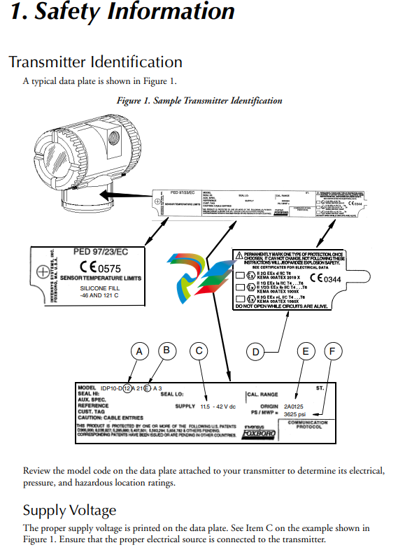
Electrical Certification Rating
The electrical safety design code is printed on the data plate as part of the model code. See Item B
on the example shown in Figure 1. See the “Product Safety Specifications” section of the
instruction pertaining to your instrument on the enclosed DVD to identify this code. The type of
protection is also marked on the data plate. See Item D on the example shown in Figure 1.
PED Certification
The PED (Harmonized Pressure Equipment Directive for the European Community)
certification is offered only with transmitters ordered with ATEX Electrical Safety Design Code
selections. Transmitters with PED certification have a CE marking on the data plate that also
carries the PED number 0496.
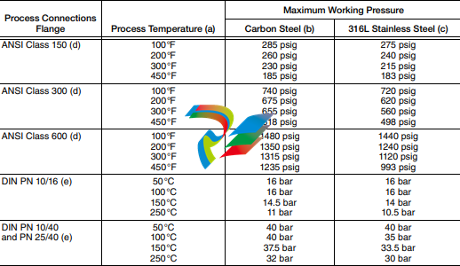
Pressure Rating
The maximum working pressure (PS or MWP) for the transmitter is printed on the data plate.
See Item F on the example shown in Figure 1.
The data plate of flanged level transmitters and transmitters with flanged pressure seals are
stamped with the MWP if the transmitter pressure range is the limiting factor. It is stamped
“Flange Rate” if the flange rating is the limiting factor. The MWP of the flanged seal is stamped
on the seal data plate. See Figure 2.
Figure 2. Sample Seal Data Plate
When using transmitters with threaded, in-line saddle weld, or sanitary pressure seals, compare
the MWP of the transmitter on the transmitter data plate and the MWP of the seals on the seals
data plates and use the lesser value as the system MWP.
The MWP on the seal data plates may not be given at your process temperature. Use the
following information and industry standards as required to determine the actual pressure limits
for your application.
MODEL CODE: PSFPS-A2S0E313B MWP: 275 psig at 100°F
NOTICE: BREAKING CONNECTIONS VOIDS WARRANTY
BE SURE FILL FLUID CAN MIX SAFELY WITH PROCESS HIGH SIDE SEAL
HIGH SIDE FLUID, DC200, 10 cSt SILICONE TEMP RANGE -40 TO +450°F
PROCESS WETTED MATERIAL 316 SS
essure Seal PSFLT
Table 1. Pressure Seal PSFLT Pressure Limits
a. Flange temperature/pressure ratings only; seal temperature ratings may be lower; refer to Table 8
b. ASME/ANSI Material Group 1.1; linear interpolation acceptable
c. ASME/ANSI Material Group 2.2; linear interpolation acceptable
d. ANSI flanges per ASME/ANSI B16.5-1988.
e. DIN flanges per BS4504.
Pressure Seals PSFPS and PSFES
Table 2. Pressure Seal PSFPS and PSFES Pressure Limits
Pressure Seals PSSCR and PSSCT
The maximum working pressure of the seal process connection varies with the clamping device
used. Refer to Tri-Clover Tri-Clamp standards to determine the pressure limits of the clamping
system that you are using.
PSSSR and PSSST (Sanitary Tank Spud) Seals
The maximum working pressure of mini tank spud seal is 1.55 MPa at 120°C (225 psi at 250°F).
That of the standard tank spud seal is 1.38 MPa at 120°C (200 psi at 250°F).
Origin Code
The origin code identifies the area of manufacture and the year and week of manufacture. See
Item E on the example shown in Figure 1. In the example, 2A means the product was
manufactured in the Measurement and Instrument Division, 01 identifies the year of
manufacture as 2001, and 25, the week of manufacture in that year.
Operating Temperature Limits
The operating temperature limits of the electronics are -40°C and +85°C (-40°F and +185°F).
The limits are -40°C and +75°C (-40°F and +167°F) for IAP10, IGP10, IGP25, and IGP50
Transmitters with ATEX flameproof certification. Ensure that the transmitter is operated within
this range.
The sensor body operating temperature limits are determined by the sensor fill fluid. The cover
material, sensor diaphragm material and fill fluid are specified by two characters in the model
code on the data plate. See Item A on the example shown in Figure 1. Also see Table 5 and
Table 6 to interpret this part of the code and Table 7 to determine the sensor body temperature
limits. In the example IDP10-D12A21E-A3, the number 12 identifies the fill fluid in Table 5 as
silicone. Table 7 identifies silicone as having temperature limits of -46 and +121°C (-50 and
+250°F).
The diaphragm material code is found in the pressure seal model number which is located on the
pressure seal. See following example:
The housing material is 316 ss.
The gasket is provided by the user.
Pressure Seals PSSCT
The housing material is 316 ss.
The diaphragm material is 316L ss.
The gasket is provided by the user.
Pressure Seals PSSSR and PSSST
The housing material is 316 ss.
The diaphragm material is 316L ss.
The gasket material is EPDM.
Warnings
General Warning
! WARNING
1. Transmitters must be installed to meet all applicable local installation regulations,
such as hazardous location requirements, electrical wiring codes, and mechanical
piping codes. Persons involved in the installation must be trained in these code
requirements to ensure that the installation takes maximum advantage of the safety
features designed into the transmitter.
2. A plug is supplied with each transmitter with 1/2 NPT conduit connection. It is
intended to provide moisture ingress protection of the unused housing conduit entry.
The plug must be wrench tight to achieve this level of protection. Thread sealant is
required. Explosion-proof applications may require a certified plug.
Housings with M20 / PG 13.5 threaded conduit connections are provided with an
ATEX certified plug. Thread sealant is required to provide moisture ingress
protection.
ATEX Warnings
! WARNING
Apparatus marked as Category 1 equipment and used in hazardous areas requiring
this category must be installed in such a way that, even in the event of rare incidents,
the versions with an aluminum alloy enclosure can not be an ignition source due to
impact and friction
Install ATEX certified transmitters in accordance with the requirements of standard
EN 60079-14.
! WARNING
To install a transmitter labeled with multiple approvals, select and permanently mark
the certification label in the tick block to distinguish the installed approval type from
the unused approval types. Once installed, the transmitter cannot be reinstalled using
any other approval type. Not following these instructions will jeopardize explosion
safety.
On IGPxx and IAPxx Transmitters with IECEx certification, the maximum constructional gap
(Ic) is less than that required by IEC 60079-1:2003 as detailed in the table below:
Explosionproof/Flameproof and Enclosure Warning
! WARNING
1. To prevent possible explosion and to maintain explosionproof/flameproof and dustignitionproof protection, plug unused openings with a certified metal pipe plug. For
1/2 NPT connections, both the plug and conduit must be engaged a minimum of five
full threads. For M20 and PG 13.5 connections, the certified plug provided and the
conduit must be engaged a minimum of seven full threads.
2. The threaded housing covers must be installed. Turn covers to seat O-ring into the
housing and then continue to hand tighten until the cover contacts the housing
metal-to-metal.
3. If the electronics housing is removed for any reason, it must be hand tightened
fully. Then engage the set screw until it bottoms out and back it off 1/8th turn. Fill
the set screw recess with red lacquer (Foxboro Part Number X0180GS or equivalent).
The housing then may be rotated up to one full turn in a counterclockwise direction
for optimum access to adjustments.
Intrinsically Safe and Type n Warning
! WARNING
Since live maintenance is not specified, to prevent ignition of flammable atmospheres,
disconnect power before servicing unless the area is certified to be nonhazardous.
Type n Warning
! WARNING
On transmitters certified for ATEX protection n, CSA Class I, Division 2, or FM
nonincendive for Class I, Division 2, the threaded housing covers must be installed.
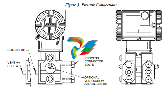
Pressure Warnings
! WARNING
When installing your transmitter, tighten process connector bolts to a torque of
61 N•m (45 ft•lb) and drain plugs and optional vent screws to 20 N•m (15 ft•lb). See
Figure 3.
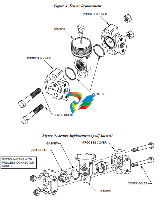
If a sensor is replaced or process covers are rotated for venting, replace the gaskets and
torque cover bolts (see Figures 4 and 5) to 100 N•m (75 ft•lb) in several even
increments. Torque values are 66 N•m (50 ft•lb) when optional 316 ss bolts are
specified (option B1). A pressure test is required. Perform a hydrostatic test with a
liquid following proper hydrostatic test procedures. Pressure test the process cover
assembly by applying a hydrostatic pressure of 150% of the maximum static and
overrange pressure rating to both sides of the process cover/sensor assembly
simultaneously through the process connections. Hold pressure for one minute. There
should be no leakage of the test fluid through the gaskets.
Process Fluid Warning
! WARNING
If process containing parts are to be disassembled:
1. Make sure that process fluid is not under pressure or at high temperature.
2. Take proper precautions concerning leakage or spillage of any toxic or otherwise
dangerous fluid. Follow any Material Safety Data Sheet (MSDS)
recommendations.
Seal or Sensor Fill Fluid Warning
! WARNING
Even though the volume of fill fluid is small, be sure that the fill fluid can mix safely
with the process fluid.
Parts Replacement Warning
! WARNING
This product contains components that have critical safety characteristics. Do not
substitute components. Replace components only with identical factory supplied
components. Component substitution may impair the electrical safety of this
equipment and its suitability for use in hazardous locations.
EU Declaration of Conformity
We, Manufacturer:
Invensys Systems, Inc.
38 Neponset Ave.
Foxboro, Massachusetts 02035
U.S.A.
declare under our sole responsibility that the
I/A Series Pressure Transmitters IGP, IAP, IDP, IPI, IMV
are in conformity with the protection requirements of Council Directives:
♦ 2004/108/EC on the approximation of the laws of the Member States relating to
Electromagnetic Compatibility
♦ 94/9/EC on the approximation of the laws of the Member States concerning
equipment and protective systems intended for use in potentially explosive
atmospheres
♦ 2014/68/EU on the approximation of the laws of the Member States concerning
pressure equipment
The basis on which Conformity is being declared:
♦ EN 61326-1:2006, Electrical equipment for measurement, control and laboratory use
EMC requirements, Class A emission limits, and immunity requirements according to
Change to enter Edit Mode. Use the Right/Left arrow keys to move the cursor under
the digits you want to change. Use the up/down arrow keys to change the digits to the
desired values. In the case of this example, continue this procedure until the display
reads [00150.0]. Use the Right arrow key to move the cursor out past the right
bracket to save the setting. The display then reads FORWARD URV? {00150.0}.
5. Now that all changes have been made, press the Right arrow key. You are asked Go
On-Line? Reply Yes by pressing the Right arrow key. Press the Right arrow key again
to begin displaying flow measurements.
Foundation Fieldbus Protocol
Your transmitter has been preconfigured at the factory to the settings shown in Appendix B.
Compare your needs to the factory configuration and note the changes to the configuration you
must make.
If the transmitter is not connected to a flowtube or IMTSIM, it is necessary to put a jumper wire
between terminals Coil 1 and Coil 2 and also to provide power to the transmitter.
This section describes the procedures to quick start the transmitter from the optional local
keypad/display. Note that after you quick start the transmitter from the local keypad, you should
use the fieldbus host to ensure that parameter values associated with the host are changed to agree
with those changed from the local keypad/display. Otherwise, mismatch errors occur when you
attempt to place the transmitter into Auto mode.
To make changes to the configuration using the local keypad/display, go to 1 TOP LEVEL/Setup
by pressing the Left arrow repeatedly until the display reads 1 TOP LEVEL. Then use the
Up/Down arrow keys to go to 1 TOP LEVEL/Setup. The procedure to change your
configuration is demonstrated by the following example:
Engineering units (EGUs) in GPM (factory default setting)
Forward direction of flow (Unidir positive – factory default setting)
Flow range 0 to 150 GPM
Flowmeter factor of 18.22 (refer to “Determining the Meter Factor” on page 18)
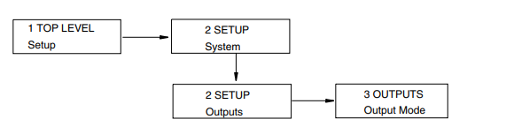
Note that the factory default engineering units is already configured as GPM, so no change is required. 2. Note that the factory Output mode is also already configured as UniDir positive, so no change in the direction is required. 3. You must enter your flow upper range value however. To do this: a. Go to Setup Level 2 by pressing the Right arrow key. Next move to 2 SETUP Outputs with the Down arrow key. Then move to 3 OUTPUTS Output Mode with the Right arrow key
b. Use the Down arrow key to go to 3 OUTPUTS Range Info and the Right arrow
key to go to FORWARD URV? {#####.#} GPM (Default {00100.0}).
c. Press the Shift + Change keys to enter Edit mode. You are asked Go Offline?
Reply Yes by pressing the Right arrow key. The display shows FORWARD URV?
[#####.#] GPM.
d. Use the Right/Left arrow keys to move the cursor under the digits you want to
change. Use the Up/Down arrow keys to change the digits to the desired values. In
the case of this example, continue this procedure until the display reads
[00150.0].
e. Using the Right arrow key, move the cursor under the right bracket and press the
key to enter the URV. The display reads FORWARD URV? {150.0} GPM.
f. Press the key again to move back to 3 OUTPUTS Range Info.
4. Lastly, you have to enter your flowmeter factor. To do this:
a. Use the Left arrow key to move to the Level 2 menu, 2 SETUP Outputs.
b. Press the Down arrow key six times to move to 2 SETUP Calibration and the
Right arrow key to move to the Level 3 menu, 3 CALIBRATION Meter Factor.
See FIgure A-5.
c. Use the Right arrow key to move to MFACTOR FORMAT? {###.######}. This
format can be changed, if necessary, to accommodate the meter factor.
d. Use the Right arrow key to move to METER FACTOR? {###.######} (Default
{012.000000}. Then press Shift + Change to enter Edit mode.
e. Use the Right/Left arrow keys to move the cursor under the digits you want to
change. Use the Up/Down arrow keys to change the digits to the desired values. In
the case of this example, continue this procedure until the display reads
[018.220000]. Use the Right arrow key to move the cursor out past the right
bracket to save the setting. The display then reads METER FACTOR?
{018.219998}. Note that in some cases, as with this example, a slightly different
value appears. The magnitude of this difference is insignificant.
NOTE
To determine the correct meter factor, refer to “Determining the Meter Factor” on
page 18.
f. Press the Right arrow key again. The display reads 3 CALIBRATION Meter
Factor.
5. Now that all changes have been made, press the Left arrow key until you are asked Go
On-Line? Reply Yes by pressing the Right arrow key. To display flow measurement,
press the Right arrow key once more.
! CAUTION
If you change the upper range value or engineering units in the Transducer Block with
the local display pushbuttons without making a corresponding change in the
corresponding Analog Input Blocks from a fieldbus host, a mismatch error occurs and
the Analog Input Block reverts to Out of Service mode.
Determining the Meter Factor
First find the “Cal Factor” or “IMT25 Cal Fact” on the flowtube data label.
If the flowtube data label has a “IMT25 Cal Fact.” listing, use that value as the “Meter Factor.”
If only a “Cal Factor” value is found on the flowtube data label, that value must be multiplied by
the appropriate factor from Table 2 to calculate the “Meter Factor.”
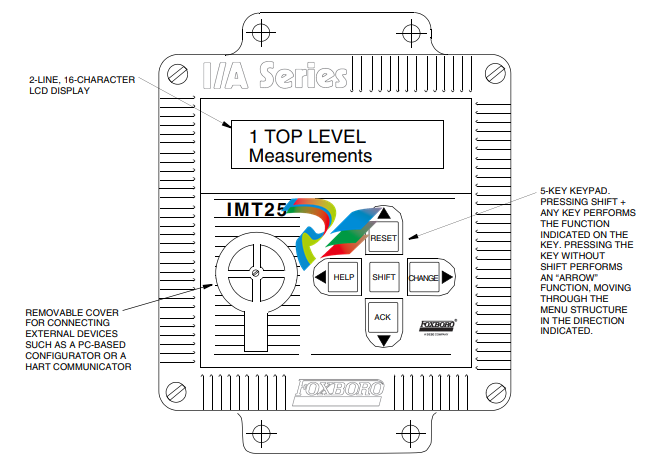
Operation from Keypad/Display Panel
For local operation, configuration, and calibration, all operator entries are made through a
5-button keypad and all data is presented on a 2-line x 16 character LCD display. The
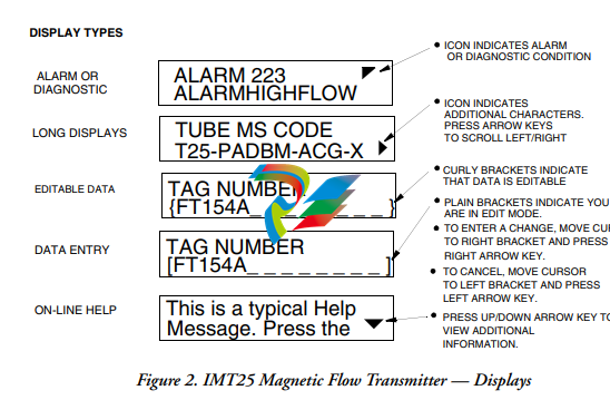
keypad/display of the IMT25 Transmitter is shown in Figure 1. Information on various types of
display is shown in Figure .
Figure 1. IMT25 Magnetic Flow Transmitter — Keypad/Display
All required functions are accomplished by using the four arrow keys alone and in combination
with the Shift key. Table 4 explains the function of each key
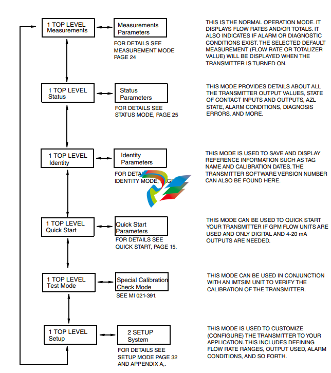
Top Level Menu
The Top Level menu displays the following modes – Measurements, Status, Identity, Quick Start
(in FoxCom and HART transmitters), Test Mode, and Setup. You can switch from one to another
in sequence by using the Up/Down arrow keys. To enter the second level menu from a particular
top level screen, press the Right arrow key. To return to the top level from a second level menu
item, press the Left arrow key. The level of the first, second, third, and fourth level menus is
indicated by the digit appearing as the first character in Line 1 of the display; a 1 indicates Level 1
(Top Level), a 2 indicates Level 2, and a 3 indicates Level 3, etc.
The top level menu is shown in Figure 3. For a complete presentation of all menu structures, refer
to Appendix A.
Measurements Mode
The Measurements mode, which is your main operating mode, is displayed upon startup.
Depending on the transmitter configuration, it has up to seven displays, any of which may be set
as the startup default. All screens can be scrolled with the Up/Down arrow keys.
Rate (EGU) — Shows current flow rate (forward or reverse) in the selected
engineering units.
Rate (% Range) — Shows current flow rate (forward or reverse) as a percentage of full
scale URV.
Fwd Tot — Shows current value of the forward totalized flow in engineering units.
Use the Net Tot display to reset.
Rev Tot — Shows current value of the reverse totalized flow in engineering units. Use
the Net Tot display to reset.
Net Tot — Shows current value of the net totalized flow (forward total – reverse total)
in selected engineering units. Press Shift + Reset to reset the displayed total to
zero. Resetting Net Tot also resets Fwd Tot and Rev Tot. It does not reset Gr Tot.
If Reset Totals is passcode protected, the message Enter Passcode appears.
Grand Tot — Shows current value of the grand total flow in engineering units. Press
Shift + Reset to reset the displayed total to zero. Resetting Gr Tot does not reset
Fwd Tot, Rev Tot, and Net Tot. If Reset Totals is passcode protected, the message
Enter Passcode appears.
If the Dual Display feature is configured On, a combination of two of these parameters can be
displayed at once. A typical dual display, in which Line 1 shows flow rate and Line 2 shows the
present forward total, is shown below. Units may not be displayed or may be truncated.
You may step through the displays of each of these parameters with the Up and Down arrow keys.
However, unless you specifically do so, the display defaults to that configured in Setup mode. The
engineering units and formats used in the displays are also configured in Setup mode.
Status Mode
The Status mode enables you to view fourteen system parameters and thus assess the performance
of the loop. You may not edit them in this mode. To step through the displays of the following
parameters, use the up/down arrow keys:
Mode — Shows the present operating mode: On-Line, Off-Line, Override, or
Calibrate. This will normally display On-Line. The other modes will only be
displayed if someone else has changed the mode with an I/A Series Workstation,
PC-Based Configurator, HART Communicator, or fieldbus host. Off-Line means
that it has been taken off-line; Override, that the measurements cannot be relied
upon because one or more of the outputs is at a preset value; and Calibrate, that the
transmitter is in Calibration mode.
Alarm — Shows the most current active alarm. If there are no active alarms but
something is in the history buffer, the display reads Alarms In Buffer. If there are
no active alarms and nothing in the buffer, display reads No Alarms.
Diagnostics — Shows No Diag, Diag Existed, or Diag Exists. If a diagnostic
problem exists, the second line identifies the problem. Help is available with the
Shift + Help keys. An active diagnostic problem cannot be cleared; the problem
must be corrected. Diag Existed means a diagnostic error did occur, but the
condition has cleared and the transmitter is working correctly. However, the Diag icon
will remain on the display until the diagnostic has been acknowledged. To clear, the
transmitter must be in the Status mode with the diag window displayed. Then use the
Shift + Ack keys.
Digital Output — If the transmitter output is in Digital Output mode, the display
shows whether the transmitter is configured for Unidirectional or BiDirectional flow.
If the transmitter is not in Digital Output mode, the screen is not displayed.
NOTE
Digital and Analog Output are mutually exclusive. Only one of the two are displayed
at any one time.
Analog Output — If the transmitter output is in Analog Output mode, the display
shows whether the transmitter is configured for U (unidirectional), U/M1
The manual is part of the product and contains important information about installation,
startup, operation and service. The manual is written for everyone installing, starting up
or servicing this product.
The manual must be accessible and legible. Make sure that persons responsible for the
system and its operation, as well as persons who work independently on the unit, have
read through the manual carefully and understood it. If you are unclear about any of the
information in this documentation, or if you require further information, contact SEWEURODRIVE.
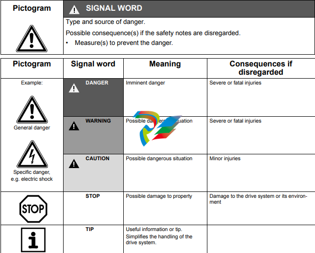
1.2 Structure of the safety notes
The safety notes in this manual are designed as follows:
1.3 Rights to claim under limited warranty
A requirement of fault-free operation and fulfillment of any rights to claim under limited
warranty is that you adhere to the information in the MOVITRAC® B documentation.
Therefore, read the operating instructions before you start working with the unit.
Make sure that the documentation is available to persons responsible for the system and
its operation as well as to persons who work independently on the unit. You must also
ensure that the documentation is legible.
1.4 Exclusion of liability
You must comply with the information contained in the MOVITRAC® B documentation
to ensure safe operation of MOVITRAC® B and to achieve the specified product characteristics and performance requirements. SEW-EURODRIVE assumes no liability for
injury to persons or damage to equipment or property resulting from non-observance of
the documentation. In such cases, any liability for defects is excluded.
Unauthorized duplication, modification, distribution or any other use of the whole or any
part of this documentation is strictly prohibited.
1.6 Content of this publication
This publication contains conditions and amendments related to MOVITRAC® B in
safety-oriented applications.
The system comprises a frequency inverter with asynchronous motor and safety-tested
external disconnecting device.
1.7 Other applicable publications
This document supplements the MOVITRAC® B operating instructions and limits the
application notes according to the following information.
It can only be used in conjunction with the following publications:
• The MOVITRAC® B operating instructions must always be observed.
For permitted connection variants, refer to chapter “Connection variants” (see page 17).
Safety Concept
• In case of danger, any potential risk related to a machine must be eliminated as
quickly as possible. Standstill with restart prevention is generally the safe condition
for preventing dangerous movements.
• MOVITRAC® B is characterized by the optional connection of X17 to an external failsafe, prototype tested safety relay. The safety relay disconnects all active elements
(disconnection of the safety oriented 24 V power supply of the output stage control)
that generate the pulse trains to the power output stage (IGBT) when a connected
control device (E-STOP button with latching function) is activated.
• Disconnecting the 24 V voltage supply at connector X17 ensures that the supply
voltages required for operating the frequency inverter and consequently for
generating a rotating field of pulse patterns (which allow the generation of a rotating
field) are safely interrupted, preventing automatic restart.
• Instead of separating the drive galvanically from the power supply using contactors
or switches, the disconnection procedure described here prevents the power
semiconductors in the frequency inverter from being activated, thus ensuring safe
disconnection. This process disconnects the rotating field generation for the
respective motor. The individual motor cannot develop any torque in this state even
though the mains voltage is still present.
• The requirements for the safety control are clearly defined in the following sections
and must be observed.
Using a suitable external circuit via a safety control
– with approval to at least EN 954-1 category 3
enables operation of the MOVITRAC® B frequency inverter with safe disconnection to stop category 0 or 1 according to EN 60204-1, fail-safe protection against
restart according to EN 1037 and fulfillment of safety category 3 to EN 954-1.
Using a suitable external circuit via a safety control
– with approval for EN ISO 13849-1, performance level “d”
enables operation of the MOVITRAC® B frequency inverter with safe disconnection according to stop category 0 or 1 to EN 60204-1, fail-safe protection against
restart according to EN 1037 and fulfillment of performance level “d” to EN ISO
13849-1.
Limitations
• Important: The safety concept is only suitable for performing mechanical work
on system/machine components.
• Important: A system/machine-specific risk analysis must always be carried out
by the system/machine manufacturer and taken into account for the use of the
MOVITRAC® B frequency inverter.
• Danger of fatal injury: When the safety-oriented 24 V voltage supply is
disconnected, the mains supply voltage is still present at the frequency
inverter DC link.
• Danger of fatal injury: When the 24 V voltage supply is disconnected, the DC
link voltage is still present at the MOVITRAC® B frequency inverter.
• Important: If work is carried out on the electrical section of the drive system,
the DC link voltage must be disconnected.
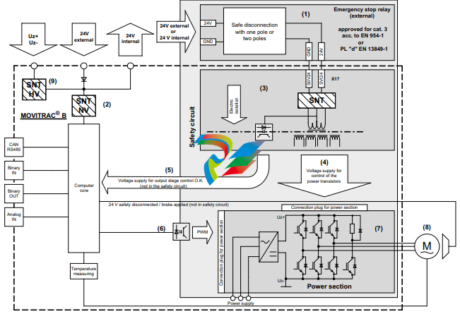
Representation of the “Safety concept for MOVITRAC® B / control unit”
[1] Safety relay (external)
[2] Low-voltage switch-mode power supply
[3] Safety switched-mode power supply (SNT)
[4] Voltage supply for controlling the power transistors
[5] Feedback to the central processing unit: Voltage supply for output stage control OK (not in safety circuit)
[6] Pulse width modulated signals for output stage
[7] Power section
[8] Motor
[9] High-voltage switch-mode power supply
Representation of the “Safety concept for MOVITRAC® B / size 0”
Safety-Relevant Conditions
The following conditions are mandatory for the installation and operation of
MOVITRAC® B in applications with safe disconnection of the drive in accordance with
category 0 or 1 of EN 60204-1 and fail-safe protection against restart according to
EN 1037, and conformance with safety category 3 of EN 954-1 or performance level “d”
of EN ISO 13849-1. The conditions are divided into the following sections:
• Approved devices
• Installation requirements
• Requirements for external safety relays
• Startup requirements
• Operation requirements
3.1 Information on the stop categories
• Stop category 0 means that the safety 24 V voltage supply can be disconnected
independent of the setpoints.
• Observe the following procedure for stop category 1:
– Decelerate the drive using an appropriate brake ramp specified by the setpoint.
– Disconnect the safety-oriented 24 V voltage supply
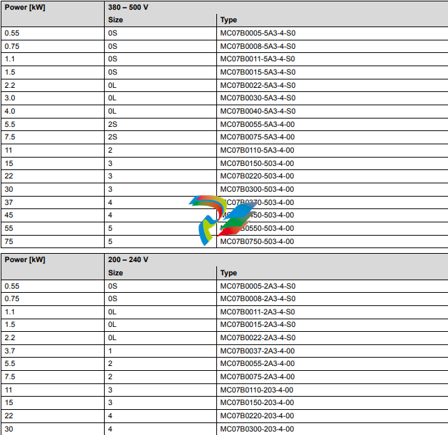
3.2 Approved devices
The following frequency inverters are permitted for applications with safe disconnection
according to stop category 0 or 1 of EN 60204-1, fail-safe protection against restart
according to EN 1037 and compliance with safety category 3 according to EN 954-1 or
performance level “d” according to EN ISO 13489-1.
3.2.1 MOVITRAC® B for AC 3 × 380 – 500 V / 200 – 240 V supply voltage
3.2.2 Hazard caused by coasting drive
Note that if the drive does not have a mechanical brake, or if the brake is defective, the
drive may coast to a halt.
Note: If coasting to a halt results in application-dependent hazards, take
additional protective measures (e.g. movable covers with closure), which cover
the hazardeous area until persons are no longer in danger.
The additional protective covers must be designed and integrated in such a way that
they meet the safety category required for the machine.
After activating the stop command, access to the machine must remain blocked until the
drive has reached standstill, or the access time has to be determined to ensure that an
adequate safety distance is maintained.
3.3 Installation requirements
Note the following instructions for applications of MOVITRAC® B with safe disconnection of the drive according to stop category 0 or 1 according to EN 60204-1 and fail-safe
protection against restart according to EN 954-1 safety category 3 or performance level
“d” according to EN ISO 13849-1.
• The line between the safety control system (or the safety-oriented tripping device)
and MOVITRAC® B terminal X17 is designated as the safety-oriented 24 V voltage
supply.
• Power lines and the safety-oriented 24 V supply voltage must be installed in separate
cable ducts.
• The safety-oriented 24 V supply voltage must be routed according to EMC guidelines
and as follows:
– Outside an electrical installation space: Shielded cables must be routed
permanently (fixed) and protected against external damage, or other equivalent
measures.
– Individual conductors can be routed inside an electrical installation space.
Observe the respective regulations governing the application.
• It must be ensured that parasitic voltages cannot be generated in the safety-oriented
24 V supply voltage.
• The total cable length between the safety control system (e.g. safety relay) and
MOVITRAC® B is limited to a maximum length of 100 m for EMC reasons.
• The switching capacity of the safety relay and the maximum permissible voltage drop
on the 24 V supply cable must be observed during disconnection of group drives.
• Only use terminal connections (terminal blocks) that meet EN 60204-1 and prevent
short-circuits.
• Observe the notes in the “MOVITRAC® B” operating instructions on EMC compliant
cabling. It is essential that you apply the shielding at both ends on the housing.
• Only use power supplies with safe isolation (SELV/PELV) according to VDE010.
According to EN 60950-1, the voltage between the outputs or between any output
and a ground part must not exceed DC 60 V voltage for longer than 0.2 s after only
one fault. The maximum DC voltage must be 120 V.
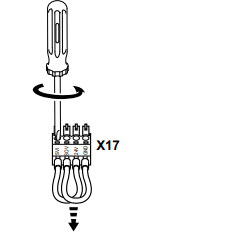
• You must remove the jumpers at X17:1 to X17:4 (see following figure) for use in
applications with safe disconnection of the drive according to stop category 0 or 1 in
accordance with EN 60204-1 and fail-safe protection against restart according to
EN 954-1 safety category 3 or performance level “d” according to EN ISO 13849-1.
• The shielded lines of the safety-oriented 24 V voltage supply (terminal X17) must be
clamped under the signaling electronics shield clamp.
• You must observe the technical data of MOVITRAC® B (see MOVITRAC® B
operating instructions).
Removing jumpers
Requirements on external safety relays
• If the requirements of the standard EN 954-1 are to be met, at least one approval for
safety category 3 according to EN 954-1 must be available.
• If the requirements of the standard EN ISO 13849-1 are to be met, at least one
approval for performance level “d” according to EN ISO 13849-1 must be available.
• If the DC 24 V voltage supply is safely disconnected at the positive pole only, no test
pulses must be applied to this pole in disconnected condition.
• Bipolar disconnection of the DC 24 V supply is permitted.
• The values specified for the safety relays must be adhered to when designing the
circuit.
• The switching capacity of the safety relays must correspond at least to the maximum
permitted limited output current of the DC 24 V voltage supply. Observe the
manufacturer’s instructions for the safety relays concerning the permitted
contact loads and fusing that may be required for the safety contacts. Unless
specified otherwise, the contacts must be protected with 0.6 times the nominal
value of the maximum contact rating specified by the manufacturer.
• The controller must be designed and connected in such a way that resetting the
control device itself will not lead to a restart. A restart may only be carried out after
an additional reset of the controller.
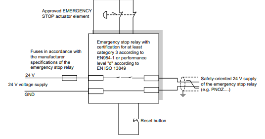
3.4.1 “Safety relay” sample circuit
The following figure shows the basic connection of an external safety relay (according
to the before mentioned requirements) to MOVITRAC® B.
The information in the respective manufacturer’s data sheets must be observed for
connection.
1-pole disconnection of the 24 V supply voltage:
3.5 Startup requirements
• Startup must be documented and the functionality of the safety functions must be
demonstrated.
• Startup checks of the disconnecting device and the correct wiring must be performed
and documented for MOVITRAC® B with safe disconnection of the drive according
to stop category 0 or 1 of EN 60204-1, fail-safe protection against restart according
to EN 1037 and compliance with safety category 3 according to EN 954-1 or
performance level “d” according to EN ISO 13849-1.
• At startup, the safety-related 24 V control voltage must be included in the functional
test.
3.6 Operation requirements
• Operation is only allowed within the limits specified in the data sheets. This applies
both to the external safety relay as well as MOVITRAC® B.
• The safety functions must be checked at regular intervals to ensure proper
functioning. The period of time between the tests should be specified in accordance
with the risk analysis.
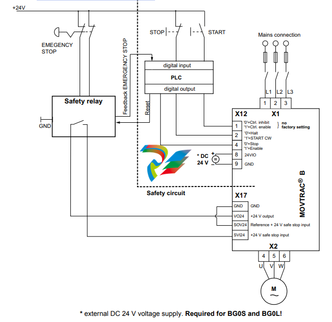
Connection Variants
Refer to the publication “Safe Disconnection for MOVITRAC® B – Applications” for
examples of approved connection variants of units listed in the section “Approved Units”
for safe disconnection of the drive according to stop category 0 or 1 of EN 60204-1 and
fail-safe protection against restart according to EN 1037 and fulfillment of the safety
category according to EN 954-1 or performance level “d” of EN ISO 13849-1. The
publication “Safe Disconnection for MOVITRAC® B – Applications” is constantly being
supplemented by possible applications. The publication includes checklists, which offer
additional assistance in project planning and installation as well as operating
MOVITRAC® B drives in safety-oriented applications. It is essential that you comply with
the publications listed in the section “Safety and warning instructions” for all the
connection variants listed in the publication “Safe Disconnection for MOVITRAC® B –
Applications”.
4.1 Disconnection of single drives
4.1.1 Requirements
The requirements of the manufacturers of safety relays (such as protecting the output
contacts against welding) or other safety components must be strictly observed. In
addition, the basic requirements described in the manual “Safe Disconnection for
MOVITRAC® B – Conditions” apply for cable routing.
For reasons of EMC, the length of the cable between connection X17 on
MOVITRAC® B and the safety components (e.g. safety relay) is limited to a maximum
of 100 m. Other instructions by the manufacturer on the use of safety relays for specific
applications must also be observed.
4.1.2 Internal 24 V supply, stop category 0
4.2 Disconnection of group drives
4.2.1 Requirements
For group drives, the 24 V supply of several MOVITRAC® B units can be made available
by a single safety relay. The maximum possible number of units (n units) results from
the maximum permitted contact load of the safety relay and the maximum permitted
voltage drop of the DC supply for MOVITRAC® B units.
Other requirements of the safety relay manufacturer (such as protecting the output
contacts against welding) must be strictly observed. In addition, the basic requirements
described in the manual “Safe Disconnection for MOVITRAC® B – Conditions” apply for
cable routing.
For reasons of EMC, the length of the cable between connection X17 (MOVITRAC® B)
and the safety components (e.g. safety relay) is limited to a maximum of 100 m.
Other instructions by the manufacturer on the safety relay used in the specific
application must also be observed.
Determining the maximum number of MOVITRAC® B drives for disconnection of group drives
The number (n units) of MOVITRAC® B units that can be connected to a group drive with
safe disconnection is limited by the following points:
1. Switching capacity of the safety relay.
A fuse must be connected in front of the safety contacts according to the
specifications of the safety relay manufacturer to prevent the contacts from sticking
or welding.
The project planner is responsible for ensuring that the specifications on the
switching capacity according to EN 60947-4-1, 02/1 and EN 60947-5-1, 11/97 as well
as on contact fuse protection given in the operating instructions of the safety relay
manufacturer are strictly observed.
2. Maximum permitted voltage drop in the 24 V power supply cable.
Values concerning cable lengths and permitted voltage drops must be observed
during project planning for group drives.
3. Maximum cable cross section of 1×1.5 mm2 or 2×0.75 mm2.
A calculation based on the technical data of MOVITRAC® B must be performed