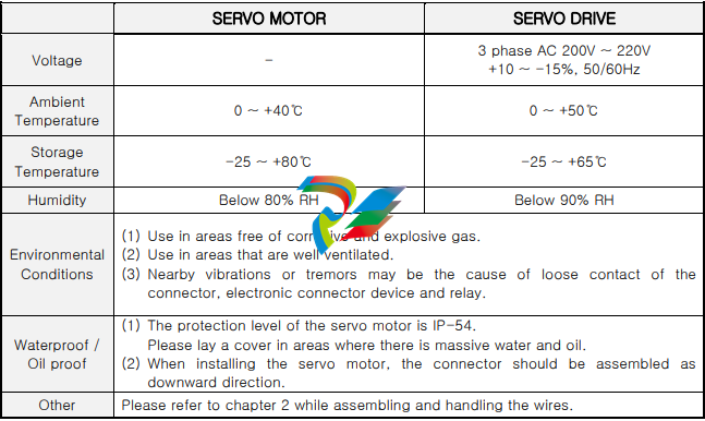
# Advant Controller 70 Manual Translation ## Advant® OCS Open Control System ## Advant Controller 70 ## ABB The Advant Controller 70 features two I/O modules and one free device connection unit. The small yet high-performance processing station The Advant Controller 70 is a small but high-performance, user-configurable processing station. It can be used either individually as an autonomous processing station or as part of an Advant OCS process control system. It can communicate with monitoring stations running under Windows and process both analog and binary signals. Therefore, the Advant Controller 70 is an ideal solution for your control engineering tasks, whether for automating a single machine or as an entry into plant-wide automation . Advant Controller 70 units communicate with each other and with other processing stations via the Advant Fieldbus 100, which is designed as a standardized twisted-pair cable. The Advant Controller can be installed in the field area near sensors and actuators to reduce cabling costs and thus overall installation costs . It offers the following advantages: – Flexibility in installation – Modular design enabling almost unlimited, step-by-step expansion – Favorable price-performance ratio, allowing savings in hardware, cabling, installation, and maintenance – Reliability and self-diagnosis for years of trouble-free plant operation – Openness through support of the OPC standard, making it possible to combine the Advant Controller 70 with OPC-compatible software of your choice . The Advant Controller 70 helps users increase their productivity and competitiveness—with peace of mind. ## ABB ## Advant Controller 70 – Compact and High-Performance ## Adaptable to Any Plant The Advant Controller 70 has a modular design and consists of passive device connection units that are mounted side by side on DIN rail profiles. These connection units gradually extend the internal module bus and provide screw terminals for connecting all incoming and outgoing process cables. The process I/O modules are plugged onto these device connection units, serving as interfaces to the outside world. Two types of device connection units are available for the process I/O modules: a compact design for vertical mounting of modules and an extended design for horizontal mounting. The former is space-saving and allows the maximum number of I/O channels per rail profile, while the latter provides more space for cabling. The extended design features fuses and terminals for powering field devices, eliminating the need for external junction boxes in most cases . Compact and extended device connection units can be used side by side within a station, meaning they can be mixed freely to adapt to the requirements of each individual field device . Since the Advant Controller 70 has low space requirements and low protection needs against environmental influences, it represents a cost-effective solution for decentralized on-site installation . ## Direct Connections to the Process Binary process I/O modules typically have 16 channels, and analog modules have 8 channels. Since an Advant Controller 70 can accommodate a maximum of 12 I/O modules, this results in a maximum of 192 binary or 96 analog signals per station, or any corresponding combination of these signals. With an additional module bus extension, a total of 24 I/O modules can be accommodated . However, up to 80 stations can be connected to a single Advant Fieldbus 100, so a system composed of multiple Advant Controller 70 units can process several thousand I/O signals . The I/O modules of a station can all be mounted on a single rail profile or distributed across multiple rail profiles, in which case they are connected to each other via pluggable cables. These different mounting options make the Advant Controller 70 suitable for installation in a wide range of standard wall-mounted enclosures and cabinets . Input and output modules for DC/AC signal levels and devices according to industry standards are available, including resistance temperature detectors and thermocouples. Therefore, process-near devices can be connected to the Advant Controller 70 with minimal signal conditioning . ## Graphical Program Creation and Open Communication The Advant Controller 70 is programmed in the user-friendly AMPL programming language. This programming language is a function block language and is equally well-suited for programming logical connections, arithmetic functions, and continuous control tasks . The user program can be divided into up to 31 subprograms, where the execution of each subprogram can be individually controlled based on logical conditions, cycle time, and priority . Thanks to its compact and robust design, the Advant Controller 70 can be installed in the field area. Operators at a central Advant OCS station can access the Advant Controller 70 in exactly the same way as any other station in the system . The Advant Controller 70 can communicate with the Advant Controller 110 in the same way as with another Advant Controller 70 . It is now easier than ever to combine Advant control systems with OPC-compatible software of your choice, such as SattGraph 5000. The Advant OPC Server, which is based on Windows NT, provides powerful, easy-to-use services for reading, writing, and subscribing to data. Thus, it is easy to implement a wide variety of applications for controlling and monitoring production processes. The Advant OPC Server for Advant Fieldbus 100 can coexist with other Windows NT-based configuration tools, such as AMPL Control Configuration. Among other things, this setup offers remote configuration and troubleshooting for nodes on the Advant Fieldbus 100. This means you can configure, commission, and maintain all your stations in the control system from a central point—with minimal effort . ## Trouble-Free Production Through Special Functions The Advant Controller 70 includes numerous functions that make the system reliable and fault-tolerant, and enable self-diagnosis; for example: – Data transmission on the fieldbus is secured by acknowledgment and checksum formation to ensure error-free operation . – The processing station supports dual redundancy for power supply and fieldbus with built-in monitoring and fault logging . – In the event of serious faults, all outputs of the processing station can be individually set to either maintain the last valid value or adopt pre-defined values, allowing the affected plant part to enter a safe state . – I/O modules can be hot-swapped during operation of the station, i.e., without switching off the power supply to system and field components. Hardware protection ensures that only modules of the correct type can be plugged into free device connection units, while software protection finally checks whether the module type is correct . With all these functions, the Advant Controller 70 helps secure crucial advantages for users of Advant OCS. The Advant Controller 70 can communicate with processing stations of the Advant Controller 400 series and via these with the entire Advant OCS process control system . ## Technical Data of Advant Controller 70 | Power Supply | Supply Voltage: 24V DC +10…-15%; Maximum Current: 1A | | — | — | | Device Connection Units (MTU) Compact Design TU810/811 | Rated Isolation Voltage: 50/250V; Conductor Cross-Sections: 0.2-2.5 mm² (AWG 24-12) | | Extended Design | TU830/831/836; Rated Isolation Voltage: 50/250V; Conductor Cross-Sections: 0.2-2.5 mm² (AWG 24-12)/0.2-4 mm² (AWG 24-10) | | Number of I/O Devices | Max. 12 per station, optional 24 | | Extension Cables | With plug, lengths: 0.3m; 0.6m; 1.2m | | Processor Module | PM 810; CPU: MC68340/16MHz; Program/RAM Memory: 256kB Flash-PROM/256kB RAM; Engineering Station Connection: RS232C port; Battery Buffering: typically 8 months | | Advant Fieldbus | Connection: 1 bus (slave), 2 dual redundant lines, twisted-pair shielded/coaxial cable/fiber optic cable; Number of Stations: max. 80 per bus; max. 32 per twisted-pair segment | | Bus Length | Max. 750m per twisted-pair segment; max. total length: 13,000m | | Binary Input Module DI810 | Number of Channels: 16; Signal Voltage/Type: 24V DC/current-sinking | | Binary Input Module DI811 | Number of Channels: 16; Signal Voltage/Type: 48V DC/current-sinking; Groups: 2 groups of 8 channels each | | Binary Input Module DI820 | Number of Channels: 8; Signal Voltage/Type: 120V AC; Groups: Individual return conductor | | Binary Input Module DI821 | Number of Channels: 8; Signal Voltage/Type: 230V AC; Groups: Individual return conductor | | Binary Output Module DO810 | Number of Channels/Groups: 16/2 groups of 8 channels each; Signal Voltage: 24V, max 0.5A DC; Type: current-sourcing/short-circuit protected | | | Signal Voltage Type: 230V, max 3A AC/DC Relay (normally open contact) | | Analog Input Module AI810 | Number of Channels/Groups: 8/shared return conductor; Measuring Range: 0(4)-20mA/0(2)-10V; Resolution: 12 Bit | | Analog Differential Input Module AI820 | Number of Channels: 4; Groups: Shared return conductor; Measuring Range: ±0-5V, ±0-10V, ±0(4)-20mA; Resolution: 12 Bit + Sign; CMRR: >60dB DC/80dB AC at 50/60Hz | | Analog RTD Input Module AI830 | Number of Channels/Groups: 8/shared return conductor; Measuring Range: Pt100, Ni100, Ni120, Cu10, Resistance 0-400 Ω; Resolution: 14 Bit | | Analog Thermocouple Input Module AI835 | Number of Channels: 8 (7+ reference channel); Groups: Shared return conductor; Measuring Range: Thermocouple Types B, C, E, J, K, N, R, S, T, ±75mV; Resolution: 14 Bit | | Analog Output Module AO810 | Number of Channels/Groups: 8/shared return conductor; Range: 0(4)-20mA; Resolution: 14 Bit; Load: 500/1000 Ω (short-circuit protected) | | Isolated Analog Output Module AO820 | Number of Channels: 4; Groups: Shared return conductor; Measuring Range: ±0-5V, ±0-10V, ±0(4)-20mA; Resolution: 12 Bit + Sign; Load: <500 Ω for current/>2k Ω for voltage | | Environmental Conditions | Temperature: max. 40°C (vertical installation) max. 55°C (horizontal installation); Protection Class: IP20 (higher with enclosure) | | Standards Complied With | EMC: EN 50081-2, EN 50082-2, EN 60439-1, EN 60950, EN 61010-1; Fieldbus: IEC 1158-2; Corrosive Gases: ISA Class G2 CSA approval applied for |
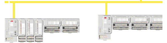
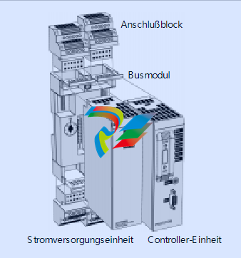
# Advant Controller 250 Automation System Manual Translation ## Advant® OCS Open Control System Advant Controller 250 ## The powerful, compact, and modular Advant Controller Advant Controller 250 is a compact, modular controller system that is built using small bus modules and can be assembled into the desired system configuration through a variety of combinations. Advant Controller 250 is configured and programmed using Advant Control Builder, an application running on Windows NT®. The Advant Controller 250 is equipped with interfaces for communication with other systems and devices. The basic hardware includes the controller unit, power supply component, bus modules, and associated cables. – Easy expandability through a compact, modular design – By selecting controller units with different performance characteristics, the system can be optimally adapted to each specific application. – Decentralized programming via Ethernet network or serial channel – I/O support for S200 I/O and S200L I/O centrally via serial I/O bus and decentrally via PROFIBUS-DP or ControlNet – I/O support for S800 I/O decentrally via PROFIBUS-DP – Communication capabilities with other control systems: MMS, SattLink, COMLI, SattBus, 3964R, and user-defined protocols (via serial channels) – Units are connected to terminal blocks and connection blocks, which simplifies installation and increases reliability. – Low installation and maintenance costs due to mounting on DIN-standard rails – Mechanical coding prevents damage from incorrect installation – CE – ABB ## Software The “Advant Control Builder” program provides the control system with a wide range of functions, such as logic functions, PID controllers, alarm processing functions, and communication capabilities with other control systems, human-machine interfaces (HMI), and systems from third-party manufacturers. ### Logic Functions Logic functions, flip-flops, timers, and counters are included in accordance with IEC Standard 61131-3. ### PID Control PID control functions are available in the controller system. ### Alarm Processing Functions for alarm and event detection, as well as for alarm printing on local printers, are available. ### Communication Communication with the programming tool is handled via a serial interface using the MMS protocol (SattLink). Communication with other systems (e.g., HMI, SCADA, and control systems) can be handled – via MMS or SattBus over Ethernet – via the SattBus fieldbus – via serial channels (RS232 or RS485). The available protocols include 3964R (as client), COMLI, and MMS (SattLink). User-defined protocols can also be used. ## Hardware Up to 16 units can be connected to the Advant Controller 250, one of which is the controller itself, which can be selected from a range of models. The units in the controller system and the I/O adapters of the central I/O system are interconnected via the controller bus. All hardware units are equipped with LED indicators on the front panel, which display signal and error status, etc. Each bus module can accommodate two hardware units. The connection blocks (200-BPP) are mounted on the bus modules, enabling easy signal connection. ### Controller Unit The controller unit is a 32-bit high-performance single-board computer available in different models (PM253, PM254, and PM255). All controller units are equipped with a floating-point processor (FPU) to improve computing performance, as well as RAM memory and a real-time clock (both battery-buffered). In addition, all models are equipped with two serial RS232 channels and a SattBus interface (except PM255, which has only one RS232 channel). ### Connection of Units On the front of the unit, there is a start mode switch for setting different program modes and a reset button for the system. The available controller models differ in terms of performance and memory configuration; further information can be found in the technical data. ### Power Supply Units The power supply units of the Advant Controller 250 use an external 24V DC power supply, which provides isolated internal power for the controller and central I/O system. #### 200-PSMG 200-PSMG is the master power supply unit, which also generates the clock frequency for the controller. The clock frequency is automatically set based on the actual system size. #### 200-PSSG 200-PSSG is a slave power supply unit used in addition to 200-PSMG to improve power supply performance in larger system configurations. ### Communication Interface External communication with the controller is conducted via interface units for Ethernet, SattBus, RS232, RS485, ControlNet, and PROFIBUS-DP. The interface for all communication units is routed via the controller bus. #### 200-CI232 200-CI232 is equipped with two non-isolated, asynchronous, serial RS232 channels with overvoltage protection. Connection is via connectors on the front or terminal blocks. #### 200-CI485G 200-CI485G is equipped with two optically isolated, asynchronous, serial RS232 channels, which are tapped via terminal blocks. Signals are galvanically isolated via optocouplers and converted to RS485 levels in the RS485 interface circuits. All signals are protected against overvoltage. The unit can be used for both half-duplex two-wire connections and full-duplex four-wire connections. An external 24V DC power supply is required for the two channels of the unit. #### 200-CIE 200-CIE is equipped with an Ethernet channel according to IEEE 802.3 and performs all logic operations for communication. The unit has an AUI port for connecting an external Ethernet transceiver (MAU) via a drop cable. The transceiver is powered via the AUI port. 200-CIE requires an external 24V DC power supply. #### 200-CISB Two galvanically isolated SattBus channels with supervisor function are available on the lower terminal block of the 200-CISB unit. Fieldbus communication for each SattBus channel is handled by a dedicated communication processor. #### 200-CICN 200-CICN is an interface for the ControlNet network and is used for connecting the decentralized I/O system. Each 200-CICN unit functions as an I/O scanner for decentralized I/O adapters of type 200-ACN. The decentralized I/O system is connected via coaxial cable or fiber optic cable. 200-CICN is connected to the ControlNet cable system via a 1m drop cable. The unit is galvanically isolated from the ControlNet via a BNC connector on the front. #### 200-CIPB/DP 200-CIPB/DP is an interface for the PROFIBUS-DP fieldbus and is used for connecting the decentralized I/O system. 200-CIPB/DP is a class 1 master unit and functions as an I/O scanner for decentralized I/O adapters of type 200-APB12. The unit is connected to PROFIBUS-DP via a front-mounted connector. ### Empty Unit #### 200-DU The 200-DU empty unit is used in empty bus module slots in the controller system. It prevents mechanical and electrical damage to the controller bus. ### Bus Module #### 200-BPN 200-BPN is used as a bus module for units of the Advant Controller 250. Each module has two slots in which units are secured with two snap locks. The bus module is designed for mounting on DIN rails and can be fastened to the rail with an additional screw for use in environments with strong mechanical loads. A maximum of 4 terminal blocks 200-BPP (2 for each hardware unit) can be mounted on the bus module. Two mechanical rotary switches, each with 8 positions, prevent incorrect hardware units from being inserted and damaging the unit. #### 200-BPP 200-BPP is a 12-pole terminal block for connecting power supply and communication signals to the controller system. If the block is mounted above the hardware unit, the terminals are numbered from 13 to 24; when connected to the bottom, they are numbered from 1 to 12. #### 200-BPT 200-BPT is a terminating resistor pair for terminating the controller bus. ### Cables #### 200-CBA/L260, 200-CBA/L260V These cables connect the controller bus module to the first central I/O adapter. 200-CBA/L260V is used for vertical mounting of the central I/O system. All required mounting parts are included. ### Miscellaneous #### 200-BPF 200-BPF is a bus module connector used to connect two bus modules. One bus module connector 200-BPF is supplied with each 200-BPN bus module. ### Decentralized I/O – ControlNet #### I/O System The ControlNet fieldbus can be operated via coaxial cable with a maximum length of 500 to 1000 m (3000 to 6000 m with repeater units), depending on the number of network nodes. S200 and S200L I/O systems are used for the central I/O connection and can be mixed. S200, S200L, and S800 I/O systems can be used for the decentralized I/O connection. When using fiber optic cables, a maximum distance of 7 km between two fiber optic repeater units can be bridged under certain circumstances. Additional fiber optic connections can be added. Depending on the selected model, up to 512 I/O units can be connected to the Advant Controller 250. The I/O adapters 200-ANN, 200-ACN, and 200-APB12 can each be operated with up to 8 I/O units. The I/O adapter CI830 can be operated with up to 24 I/O units. Up to seven additional rows of I/O units can be connected to the CI830 adapter via optical cables and optical interface units TB820. The interface unit 200-CICN can be operated with a maximum of 248 I/O units (distributed across up to 15 adapters of type 200-ACN). ### Decentralized I/O – PROFIBUS-DP The PROFIBUS-DP fieldbus can be operated with a maximum length of 100 to 1200 m, depending on the transmission speed. The interface unit 200-CIPB/DP can be operated with a maximum of 512 I/O units, distributed across up to 99 adapters 200-APB12 or up to 79 adapters CI830, or a combination thereof (total up to 99). ### Central I/O The central I/O system is housed in the same control cabinet as the Advant Controller 250 and can be operated with a maximum of 48 I/O units (distributed across 6 adapters of type 200-ANN). ## Technical Data ### General Data | Power Supply | +24 V (DC 19.2–30 V) including 5% ripple according to IEC Standard 61131-2 Type 1, i.e., +20%, -15% and max. 5% ripple | |————–|———————————————————————————————————————–| | Temperatures | Operating: +5°C to +55°C; Non-operating: -25°C to +70°C | | Humidity | Max 90%, no condensation | | Protection Class / Approvals (if applicable) | IP20; CE mark; meets the requirements of EN 50082-2. Low Voltage Directive 73/23/EEC with amendment 93/68/EEC according to standards IEC 61131-2 (only applicable to units connected to AC 50–1000 V and/or DC 75–1500 V). UL approval for USA and Canada according to UL 508 (except 200-CIPB/DP) | | Packaging Volume of Central System Units | 1–2 units: H 279 x W 360 x D 90 mm (9 dm³); 3–8 units: H 265 x W 265 x D 175 mm (12 dm³) | ### Controller Units | Processor Type | | |—————-|—————————————————————–| | PM253 | Motorola MC68020 | | PM254 | Motorola MC68020 | | PM255 | Motorola MC68060 | | Clock Frequency | | | PM253 | 16.7 MHz | | PM254 | 28.8 MHz | | PM255 | 50 MHz | | Floating-Point Processor (FPU) | Yes | | Memory and I/O Support for System and Application Program | | | PM253V01 | 1 MB RAM, 32 I/O units | | PM253V02 | 2 MB RAM, 64 I/O units | | PM254V04 | 4 MB RAM, 128 I/O units | | PM254V08 | 8 MB RAM, 256 I/O units | | PM255V04 | 4 MB RAM, 256 I/O units | | PM255V08 | 8 MB RAM, 512 I/O units | | Status Indicators | | |——————-|—————————————————————–| | PM253 and PM254 / PM255 | Green LED indicators for power OK (PWR), SattBus signals (SB TD0, SB RD0), signals TD0, TD1, RD0, and RD1 of the serial channel; red LED indicators for errors and system stop. / Green LED indicators for power OK (PWR), and signals TD0 and RD0 of the serial channel; red LED indicators for errors and system stop; red/green LED for battery status. | | Communication Channels | | | Serial Channels Baud Rate | Max cable length: 15 m; 75, 110, 134, 150, 300, 600, 1200, 2400, 4800, 9600 (standard), 19200, and 38400 Baud | | PM253 and PM254 | 2 RS232 channels. Channel 0: TD, RD, RTS, CTS, DCD, and DTR; Protocol: MMS (SattLink). Channel 1: RD and TD. Data bits: 7 or 8 (standard). Parity: odd, even, none. Stop bits: 1 (standard) or 2. Protocol: see 200-CI232. | | PM255 | 1 RS232 channel. Channel 0: TD, RD, RTS, and CTS. Protocol: MMS (SattLink). | | SattBus | 1 channel, supervisor function (not available for PM255). Protocol: see 200-CISB. | | Real-Time Clock | Yes | | Accuracy, Normal Mode | | | PM253 and PM254 / PM255 | 10 ppm (approx. 6 min/year) / 100 ppm (approx. 60 min/year) | | Accuracy, Battery-Buffered Mode | 50 ppm (approx. 0.2 s/year) | | PM253 and PM254 | Lithium battery for memory retention and real-time clock (3.6 V; 1.75 Ah; type AA/R6/UM-3) including connection cable. | | PM255 | Rechargeable NiMH battery for memory retention and real-time clock (4.8 V; 200 mAh; type 4 x V250H); buffer time approx. 1 hour. | | Connections | One 200-BPP terminal block; one 9-pin D-SUB socket on the front. | | Grounding | Directly via bus module 200-BPN | | Power Supply | Via power supply unit 200-PSMG/PSSG | | Internal Power Consumption (from 200-PSMG/PSSG) | Max 0.6 A | | Bus Module Code | 5 | | Weight | 0.430 kg without packaging; 0.500 kg with packaging | | Dimensions | H 163 x W 45 x D 91 mm (excluding connections and snap locks) | | Order Codes | PM253V01, PM253V02, PM254V04, PM254V08, PM255V04, PM255V08 | ### Power Supply Unit 200-PSMG | Input | DC 24 V (19.2–30 V including max. 5% ripple); max. 1.3 A | |———————|————————————————————————-| | Input Protection | 2 A slow-blow, 250 V; IEC-127-3 microfuse TR5 | | Inrush Current | Max 4 A for 10 ms | | Voltage Drop Compensation | Max 0.3 ms | | Output | DC 7–9 V; max. 2.2 A (1.8 A when additional 200-PSSG is used) | | Clock Frequency | 4, 6, 8, and 12 MHz, automatically set based on system configuration size | | Status Indicators | Green LED indicators for output voltage and clock output; Red LED indicators for initialization error and voltage error | | Galvanic Isolation | AC 500 V effective between input and output | | Connections | One 200-BPP terminal block | | Grounding | Directly via bus module 200-BPN | | Bus Module Code | 7 | | Weight | 0.170 kg without packaging; 0.240 kg with packaging | | Dimensions | H 163 x W 45 x D 91 mm (excluding connections and snap locks) | | Order Code | 200-PSMG | ### Power Supply Unit 200-PSSG | Input | DC 24 V (19.2–30 V including max. 5% ripple); max. 1.3 A | |———————|————————————————————————-| | Input Protection | 2 A slow-blow 250 V; IEC-127-3 microfuse TR5 | | Inrush Current | Max 4 A for 10 ms | | Output | DC 7–9 V; max. 1.8 A | | Status Indicators | Green LED for output voltage; Red LED for voltage error | | Galvanic Isolation | AC 500 V effective between input and output | | Connections | One 200-BPP terminal block | | Grounding | Directly via bus module 200-BPN | | Bus Module Code | 7 | | Weight | 0.170 kg without packaging; 0.240 kg with packaging | | Dimensions | H 163 x W 45 x D 91 mm (excluding connections and snap locks) | | Order Code | 200-PSSG | ### RS232 Communication Interface 200-CI232 | Number of Channels | 2 | |————————–|————————————————————————-| | Communication Protocols | COMLI (client and server), 3964R (client), MMS (SattLink) (client and server), and user-defined | | Communication Interface | Asynchronous, serial RS232C communication for TD, RD, RTS, CTS, DCD, and DTR | | Status Indicators | Green LED indicators for power OK and serial signals RD0, RD1, TD0, TD1, RTS0, and RTS1 | | Galvanic Isolation | None | | Transmission Speeds | 75, 110, 134, 150, 300, 600, 1200, 2400, 4800, 9600 (standard), 19200, and 38400 Baud; max. cable length: 15 m | | Data Bits | 7 or 8 (standard) | | Parity | Odd, even, none | | Stop Bits | 1 (standard) or 2 | | Max. Load on DTR | 5 mA | | Power Supply | Via 200-PSMG/PSSG power supply units | | Internal Power Consumption (from 200-PSMG/PSSG) | Max 0.2 A | | Connections | Two 200-BPP terminal blocks; two 9-pin D-SUB sockets on the front | | Bus Module Code | 8 | | Weight | 0.200 kg without packaging; 0.270 kg with packaging | | Dimensions | H 163 x W 45 x D 91 mm (excluding connections and snap locks) | | Order Code | 200-CI232 | ### RS485 Communication Interface 200-CI485G | Number of Channels | 2 | |————————–|————————————————————————-| | Number of Network Nodes | 32 per channel | | Communication Protocols | COMLI (client and server), 3964R (client), MMS (SattLink) (client and server), and user-defined | | Communication Interface | Asynchronous, serial RS485 communication for TD, RD, and RTS | | Status Indicators | Green LED indicators for power OK and serial signals RD0, RD1, TD0, TD1, RTS0, and RTS1 | | Galvanic Isolation | AC 500 V effective; channels are individually isolated from main logic and DC 24 V | | Transmission Speeds | 75, 110, 134, 150, 300, 600, 1200, 2400, 4800, 9600 (standard), 19200, and 38400 Baud; max. cable length: 1200 m | | Data Bits | 7 or 8 (standard) | | Parity | Odd, even, none | | Stop Bits | 1 (standard) or 2 | | Power Supply | Via 200-PSMG/PSSG power supply units and external power supply (DC 24 V) | | Internal Power Consumption (from 200-PSMG/PSSG) | Max 0.2 A | | External Power Consumption | Max 0.1 A (from external DC 24 V) | | Connections | Two 200-BPP terminal blocks | | Bus Module Code | 8 | | Weight | 0.220 kg without packaging; 0.290 kg with packaging | | Dimensions | H 163 x W 45 x D 91 mm (excluding connections and snap locks) | | Order Code | 200-CI485G | ### Ethernet Interface 200-CIE | Number of Channels | 1 | |————————–|————————————————————————-| | Communication Standard | IEEE 802.3 (Ethernet) | | Communication Protocols | SattBus (client and server), MMS (client and server) | | Status Indicators | Green LED indicators for power OK, data transmit (TD0), data receive (RD0), and Ethernet traffic (NET); red error LED (software-controlled) | | Galvanic Isolation | DC 500 V DC from 24 V DC power supply; according to IEEE 802.3 standard, the transceiver (MAU) must provide isolation between AUI cable and broadband coaxial medium. Any power supplied by the AUI must not exceed 0.5 A from the AUI voltage source. Further details can be found in ANSI/IEEE Std. 802.3 and SS-ISO 8802-3. | | Transmission Speed / Access Method | 10 Mbit/s / CSMA/CD (Carrier Sense Multiple Access with Collision Detection) | | Input Protection | 1.25 A slow-blow, IEC-127-3 microfuse TR5 | | Power Supply | Via 200-PSMG/PSSG power supply unit and external power supply (DC 24 V) | | Internal Power Consumption (from 200-PSMG/PSSG) | Max 0.25 A | | External Power Consumption | Max 0.5 A at DC 19.2 V (typically 0.2 A) from external 24 V DC power supply (depending on transceiver type) | | Connections | One 200-BPP terminal block; one front-mounted 15-pin D-SUB socket with slide lock | | Bus Module Code | 8 | | Weight | 0.340 kg without packaging; 0.410 kg with packaging | | Dimensions | H 163 x W 45 x D 91 mm (excluding connections and snap locks) | | Order Code | 200-CIE | ### SattBus Interface 200-CISB | Number of Channels | 2 | |————————–|————————————————————————-| | Number of Network Nodes | 120 | | Communication Protocol | SattBus (client and server) | | Transmission Speed | 62.5 kBit/s | | Access Method | Token passing | | Status Indicators | Green LED indicators for power OK, data transmit (TD0, TD1), and data receive (RD0, RD1) | | Galvanic Isolation | AC 500 V; channels are individually isolated via signal transformers | | Connection | One 200-BPP terminal block | | Power Supply | Via 200-PSMG/PSSG power supply unit | | Internal Power Consumption (from 200-PSMG/PSSG) | Max 0.3 A | | Bus Module Code | 8 | | Weight | 0.250 kg without packaging; 0.320 kg with packaging | | Dimensions | H 163 x W 45 x D 91 mm (excluding connections and snap locks) | | Order Code | 200-CISB | ### ControlNet Interface 200-CICN | Number of Channels | 1 | |————————–|————————————————————————-| | Communication Protocol | ControlNet | | Access Method | CTDMA (Concurrent Time Division Multiple Access) | | Galvanic Isolation | Isolation via signal transformers | | Transmission Speed | 5 Mbit/s | | Status Indicators | Green/red LED indicators for OK status and COM A and B (communication information); green LED for power OK | | Power Supply | Via 200-PSMG/PSSG power supply unit | | Internal Power Consumption (from 200-PSMG/PSSG) | Max 0.5 A | | Connection | 75 Ω BNC on the front | | Bus Module Code | 8 | | Weight | 0.250 kg without packaging; 0.330 kg with packaging | | Dimensions | H 163 x W 45 x D 91 mm (excluding connections and snap locks) | | Order Code | 200-CICN | ### PROFIBUS-DP Interface 200-CIPB/DP | Type | DP master class 1 | |————————–|————————————————————————-| | Number of Channels | 1 | | Communication Protocol | PROFIBUS-DP | | Transmission Speeds | 9.6; 19.2; 93.75; 187.5; 500; 1500; 3000; 6000; or 12000 kBit/s | | Galvanic Isolation | None | | Status Indicators | Green LED indicators for power OK, Ready, and Run; red error LED (for future use) | | Power Supply | Via 200-PSMG/PSSG power supply unit | | Internal Power Consumption (from 200-PSMG/PSSG) | Max 0.65 A | | Connections | One 9-pin D-SUB socket | | Bus Module Code | 8 | | Weight | 0.270 kg without packaging; 0.330 kg with packaging | | Dimensions | H 163 x W 45 x D 91 mm (excluding connections and snap locks) | | Order Code | 200-CIPB/DP | ### Empty Unit 200-DU | Bus Module Code | None | |——————-|————————————————————————-| | Weight | 0.110 kg without packaging; 0.180 kg with packaging | | Dimensions | H 163 x W 45 x D 91 mm | | Order Code | 200-DU | ### Bus Module 200-BPN / Bus Module Terminating Resistor 200-BPT | Number of Plugs (200-BPT) | One green start plug and one red stop plug | |—————————|————————————————————————-| | Internal Power Consumption (from 200-PSMG/PSSG) (200-BPT) | 0.2 A | | Weight (200-BPT) | 0.010 kg | | Dimensions (200-BPT) | H 32 x W 23 x D 17 mm | | Order Code (200-BPT) | 200-BPT | | Number of Slots (200-BPN) | 2 | |—————————|————————————————————————-| | Internal Power Consumption (from 200-PSMG/PSSG) (200-BPN) | Max 0.04 A; the power consumption is included in the specifications for central system units and does not need to be considered separately when calculating total power consumption. | | Connections (200-BPN) | The number of 200-BPP terminal blocks depends on the installed units. 2 x 32-pin Euro connectors for electrical connection of bus module and units | | Mounting (200-BPN) | On 35 x 7.5 mm rail according to DIN standard EN 50022 | | Weight (200-BPN) | 0.170 kg without packaging; 0.240 kg with packaging | | Dimensions (200-BPN) | Height: 239 mm with one terminal block; 163 mm without terminal block. Width: 91 mm excluding 5 mm wide connecting clip to next bus module. Depth: 43 mm (127 mm including unit with front connectors and DIN rail). | | Order Code (200-BPN) | 200-BPN | ### Controller Bus Cable 200-CBA/L260 | Rail Distance (Center to Center) | Max 255 mm | |———————————-|————————————————————————-| | Weight | 0.092 kg | | Order Code | 200-CBA/L260 | ### Controller Bus Cable 200-CBA/L260V | Weight | 0.092 kg | |————–|————————————————————————-| | Order Code | 200-CBA/L260V | ### Terminal Block 200-BPP | Terminal Screws | 12 | |—————–|————————————————————————-| | Cable | Solid or flexible 0.5–2.5 mm² (AWG 20–AWG 12) | | Weight | 0.070 kg | | Dimensions | H 60 (only 37 mm when installed) x W 45 x D 43 mm | | Order Code | 200-BPP | ### Programming Cable 200-CPC (Optional) | Connections | One 9-pin D-SUB socket | |————-|————————————————————————-| | Weight | 0.125 kg | | Length | 3.00 m | | Order Code | 200-CPC | ControlNet is a trademark of Allen-Bradley Company, Inc., a Rockwell International Company. Windows is a registered trademark of Microsoft Corporation.
# Advant Controller 250 ## 1、System Overview Advant Controller 250 is a compact, modular controller system that is built using small bus modules and can be assembled into the desired system configuration through a variety of combinations . It is configured and programmed using Advant Control Builder, an application running on Windows NT® . The system features interfaces for communication with other systems and devices, with basic hardware including a controller unit, power supply part, bus modules, and associated cables . It offers simple expandability due to its compact, modular design and can be optimally adapted to each specific application by selecting controller units with different performance characteristics . ## 2、Hardware Components ### 1. Core Components – **Controller Unit**: It is a 32-bit high-performance single-board computer available in various models (PM253, PM254, and PM255). All controller units are equipped with a floating-point processor (FPU) to improve computing performance, as well as battery-buffered RAM and a real-time clock . In addition, all models have two serial RS232 channels and a SattBus interface (except PM255, which has only one RS232 channel) . The available controller models differ in terms of performance and memory expansion . – **Power Supply Units**: The power supply units of the Advant Controller 250 use an external 24V DC power supply, which provides the isolated internal power supply for the controller and the central I/O system . 200-PSMG is the master power supply unit that also generates the clock frequency for the controller, which is automatically set depending on the actual system size . 200-PSSG is a slave power supply unit used in addition to 200-PSMG to improve power supply performance in larger system configurations . – **Bus Modules and Auxiliary Components**: 200-BPN is used as a bus module for the units of the Advant Controller 250. Each module has two slots where the units are fastened with two snap locks . 200-BPP is a 12-pole screw terminal block for connecting power supply and communication signals to the controller system . 200-BPT is a terminating resistor pair for terminating the controller bus . The empty unit 200-DU is used in empty bus module slots in the controller system to prevent mechanical and electrical damage to the controller bus . ### 2. Communication Interfaces The system supports a variety of communication interfaces to meet different scenario requirements, as follows: |Interface Model|Type|Core Features|Protocol Support| |—-|—-|—-|—-| |200-CI232|RS232|2 non-isolated, asynchronous serial RS232 channels with overvoltage protection|COMLI (Client and Server), 3964R (Client), MMS (SattLink) (Client and Server), and user-defined|| |200-CI485G|RS485|2 opto-isolated, asynchronous serial channels, usable for half-duplex two-wire and full-duplex four-wire connections|COMLI (Client and Server), 3964R (Client), MMS (SattLink) (Client and Server), and user-defined|| |200-CIE|Ethernet|Features one Ethernet channel according to IEEE 802.3, with an AUI port|SattBus (Client and Server), MMS (Client and Server)|| |200-CISB|SattBus|Two isolated SattBus channels with supervisor function, fieldbus communication handled by separate communication processors|SattBus|| |200-CICN|ControlNet|Interface for the ControlNet network, used for connecting the decentralized I/O system|ControlNet|| |200-CIPB/DP|PROFIBUS-DP|Class 1 master unit, used for connecting the decentralized I/O system|PROFIBUS-DP|| ## 3、Software Functions The “Advant Control Builder” program provides the control system with a wide range of functions, such as logic functions, PID controllers, alarm processing functions, and communication capabilities with other control systems, human-machine interfaces (HMI), and systems from third-party manufacturers . Logic functions, flip-flops, timers, and counters are included in accordance with the IEC Standard 61131-3 . PID control functions are available in the controller system . Functions for alarm and event detection, as well as for alarm printing on local printers, are available . Communication with the programming tool is handled via a serial interface using the MMS protocol (SattLink) . Communication with other systems (e.g., HMI, SCADA, and control systems) can be handled via MMS or SattBus over Ethernet, via the SattBus fieldbus, or via serial channels (RS232 or RS485) with protocols such as 3964R (as client), COMLI, and MMS (SattLink) available, and user-defined protocols can also be used . ## 4、I/O Configuration – **Central I/O**: The central I/O system is housed in the same control cabinet as the Advant Controller 250 and can be operated with a maximum of 48 I/O units (distributed across 6 adapters of type 200-ANN) . The S200 and S200L I/O systems are used for the central I/O connection and can be mixed . – **Decentralized I/O** – S200, S200L, and S800 I/O systems can be used for the decentralized I/O connection . – ControlNet: The ControlNet fieldbus can be operated via a coaxial cable with a maximum length of 500 to 1000 m (3000 to 6000 m with repeater units) depending on the number of network nodes . Using optical fibers (LWL), a maximum distance of 7 km between two LWL repeater units can be bridged under certain circumstances . The 200-CICN interface unit can be operated with a maximum of 248 I/O units (distributed across up to 15 adapters of type 200-ACN) . – PROFIBUS-DP: The PROFIBUS-DP fieldbus can be operated with a maximum length of 100 to 1200 m depending on the transmission speed . The 200-CIPB/DP interface unit can be operated with a maximum of 512 I/O units, distributed across up to 99 adapters 200-APB12 or up to 79 adapters CI830 or a combination thereof (total up to 99) . ## 6、Technical Data – **Power Supply**: +24 V (DC 19.2–30 V) including 5% ripple according to IEC Standard 61131-2 Type 1, i.e., +20%, -15% and max. 5% ripple . – **Temperatures**: Operating temperature: +5°C to +55°C; Storage temperature: -25°C to +70°C . – **Humidity**: Max 90%, no condensation . – **Protection Rating and Approvals**: IP20; CE mark; meets the requirements of EN 50082-2; Low Voltage Directive 73/23/EEC with Amendment 93/68/EEC according to IEC 61131-2 (only applicable to units connected to AC 50–1000 V and/or DC 75–1500 V); UL approval for USA and Canada according to UL 508 (except 200-CIPB/DP) .
# Product Summary of Advant Controller 210 ## I. Product Positioning and Core Configuration Advant Controller 210 is a compact and cost-effective open control system (Advant® OCS) launched by ABB, belonging to the Advant product series. Its configuration and programming are performed via the **Advant Control Builder** software running on the Windows NT system. It holds CE and UL certifications, making it suitable for industrial control scenarios. ## II. Hardware Features 1. **Basic Structure and Interfaces** – Adopts a compact design, supports DIN rail mounting, and is equipped with detachable power supply and I/O terminal blocks for easy installation and maintenance. – Integrates 10 binary inputs and 6 binary outputs, which can be expanded to connect up to 16 external I/O units to meet control needs of different scenarios. – Incorporates 2 RJ-45 interfaces for RS232 communication, with 2 slots for optional interface units (such as the CI274 unit supporting PROFIBUS-DP). – Equipped with 3 LED indicators (displaying power, fault, and program stop status), as well as a reset button, start/stop switch, and operation mode selection switch, facilitating status monitoring and operation. 2. **I/O System Support** – **Central I/O**: Supports S200/S200L series I/O, which can be connected centrally via a serial bus or distributed via PROFIBUS-DP; up to 8 external I/O units can be directly plugged into the controller and mounted on the same DIN rail, and an additional 8 can be connected via the TK210 cable and 200-AIO adapter. – **Distributed I/O**: The optional PROFIBUS-DP interface unit CI274 supports distributed connection of S800 series I/O (requiring the CI830 adapter). S200/S200L series can be connected via the 200-APB12 adapter, with a single adapter supporting up to 8 I/O units. 3. **Optional Components** – **Battery/Real-Time Clock Unit (SB210)**: Includes a 3.0V lithium-manganese battery (model CR2430), which can maintain RAM data for approximately 1 year, record power-off duration, and supports hot-swap replacement. Without this unit, RAM data will be lost about 20 minutes after power-off. – **Programming Cable (TK211)**: 3 meters in length, with a 9-pin D-SUB interface and an 8-pin RJ-45 connector at both ends, used to connect a PC to the RS232 channel of the controller. ## III. Software Functions (Advant Control Builder) 1. **Core Control Functions** – Includes logic functions (flip-flops, timers, counters, etc.) compliant with the IEC 61131-3 standard, PID regulation functions, as well as alarm/event recognition and local print output functions. 2. **Communication Capabilities** – Communicates with programming tools via a serial interface based on the MMS protocol (SattLink). – Communicates with external systems (such as HMI, SCADA) via the RS232 channel, supporting 3964R (client), COMLI, MMS protocols, and custom protocols. ## IV. Technical Parameters 1. **Environment and Certifications** – Operating temperature: 5°C~55°C during operation, -25°C~70°C during storage; humidity 5%~95% (non-condensing), protection class IP20. – Certifications: Compliant with CE standards (EN 50081-2/EN 50082-2) and UL 508 certification (for the US and Canada). 2. **I/O Technical Details** – **Inputs**: 10 positive logic inputs, supporting 15~30V DC signals, with second-order low-pass filters (time constant adjustable from 0.5~32ms), maximum input impedance of 6.2kΩ. – **Outputs**: 6 positive logic outputs, supporting 19~30V DC signals, maximum output current of 3A per unit, 600mA per channel, with short-circuit, over-temperature (approximately 160°C), and undervoltage (when +24V drops below 8V) protection. 3. **Communication Parameters** – **RS232 channels**: 2 channels, channel 0 has a fixed baud rate of 9600 Baud, channel 1 supports 75~38400 Baud, maximum cable length of 15 meters. – **PROFIBUS-DP (CI274)**: Class 1 master, transmission rates from 9.6 kBit/s to 12 MBit/s, maximum distance of 100~1200 meters (depending on the rate), no galvanic isolation, power consumption of approximately 700mA (DC 5V). 4. **Dimensions and Weight** – Controller dimensions: 282×107×55mm; SB210 dimensions: 44×57mm (weight 15g); TK211 cable weight: 125g. ## V. Ordering and Support – Main component order codes: PROFIBUS-DP interface (CI274), battery unit (SB210), replacement battery (CR2430), programming cable (TK211). – ABB’s global regional centers provide technical support, covering Europe, the Americas, Germany, and the Asia-Pacific region (see the original text for specific contact information).
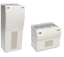
# Summary of ASTAT® Crane Control System ## I. Product Positioning and Core Advantages ASTAT® is a digital crane motion controller launched by ABB, specifically designed for industrial cranes. It is suitable for both new installations and retrofit projects, enabling powerful, responsive, and accurate control in various complex environments. Its core advantages include: – **High Adaptability**: It can operate in harsh environments such as high temperatures (e.g., regions like India), extreme cold, and dusty conditions without additional cooling or air conditioning, and can also adapt to unstable power supply systems. – **High Integration**: It integrates functions such as brake control, time relays, logic control, and thermistor relays to form a complete and fully tested motion control system, with hardware reliability far exceeding that of general-purpose products. – **Low Maintenance Costs**: By optimizing the control of rotor contactors, it significantly reduces wear on contactors and mechanical components; slip-ring motors have low maintenance requirements, with brushes replaced only every 5 to 10 years. ## II. Core Functions and Technical Features 1. **Motion Control Performance** – Adopts digital control technology, supporting two modes: scalar speed control or vector-based torque control. The motion precision can reach a微调 level of only 1 cm, achieving smooth acceleration and deceleration to reduce torque peaks, as well as rope and brake wear. – In most cases, no tachometer or pulse encoder is needed; speed is calculated by measuring rotor frequency via slip-rings. Speed feedback options include rotor frequency, tachometer, and pulse encoder. – The speed reference generation and closed-loop speed regulator execution cycle is 10 ms, the current regulator response cycle is 3 ms (interrupt-controlled), and the rotor frequency measurement resolution is 100 µs. 2. **Key Function Extensions** – Supports optional functions such as Sway Control System, positioning system for TCP/IP commands, and four-rope grab crane control. – Features logic control functions including Master-Follower, shared motion, two operator stations, and switching between different parameter sets. – Equipped with a built-in fault diagnosis system; combined with a PC maintenance program, problems can be remotely diagnosed on a ground-level computer, reducing downtime. 3. **Hardware Configuration** – **Control Module (DARA 1001)**: Supports 115/230 V AC single-phase power supply, integrating RS232 programming/monitoring interfaces, opto interfaces, digital I/O (110 V DC input, relay output), analog I/O (±20 mA/±10 V), and motor PTC inputs. – **Thyristor Modules (DASD)**: Support a maximum voltage of 690 V, with a current range of 25 A-1000 A (maximum 1000 A per module, total maximum current 2000 A), available in three frame sizes: 25-100 A, 200-355 A, and 630-1000 A. – **Remote I/O (DAPM 100)**: Provides 24 V DC digital I/O and analog I/O, supporting “Cabin I/O” configuration. ## III. Technical Parameters – **Operation Limits**: – Voltage: Nominal value -30% … +10%, supporting specifications such as 380-400 V, 415 V, 440-480 V, 500-575 V, 690 V AC; – Frequency: 50 Hz ±10 Hz or 60 Hz ±10 Hz; – Temperature: -25℃ (-40℃ short-term) without heating, +70℃ (+85℃ short-term) without cooling; – Isolation: Complies with EN60664 standard, pollution degree 4. – **Configuration Requirements**: Configured via PC, requiring Windows system and COM1/USB port. Status indication is two digits (00-99), with a readable temperature range of -40℃ … +85℃.