The GE Multilin 515 Blocking and Test Module has the following features:
• 14 Pole switchbank
• CT inputs short when current switches are opened
• Current injection for each phase
• Ground terminal
• Ability to visually isolate (open) trip relay output circuits
• Cover provided
• Suitable for utility and industrial use
• 515 test plugs available
Description
The 515 Blocking and Test Module provides an effective means of trip blocking, relay isolation and testing of GE Multilin relays. By opening the
switches and inserting test plugs, phase and residual currents from the primary CTs can be monitored. Currents can be injected into the relay from
a secondary injection test set during commissioning.
Prior to testing, the trip and auxiliary circuits must first be opened to prevent nuisance tripping; CTs can then be shorted. Conversely, when the test
is complete and the relay put back into operation, the CT switches should be closed first to ensure normal operation of the relay, prior to closing
the trip and auxiliary circuits.
Installation
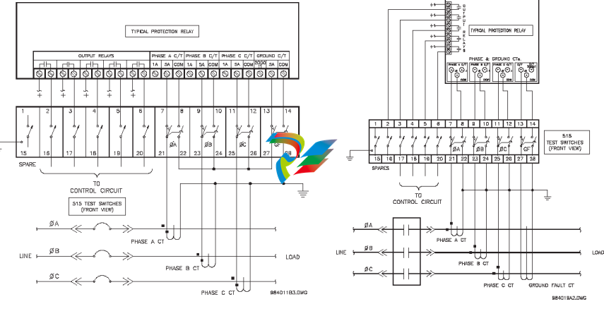
Shorting switches are provided for connection of 3 phase CTs (current transformers) and a separate core balance ground fault CT or 3 phase CTs
connected for residual ground fault sensing.
When each CT switch is opened, the CT is shorted. It is essential that the CT is connected to the shorted side of the switch as shown in the following
figure, otherwise dangerously high voltages would be present from the open circuited CTs.
When the switches are open, test plugs can be inserted to either inject signals into the relay wired to the switches or monitor signals such as CT
current from the switchgear.
Figure 1: Typical wiring for connecting a 515 to a protective relay Figure 2: Typical Wiring for Zero-Sequence Ground Fault
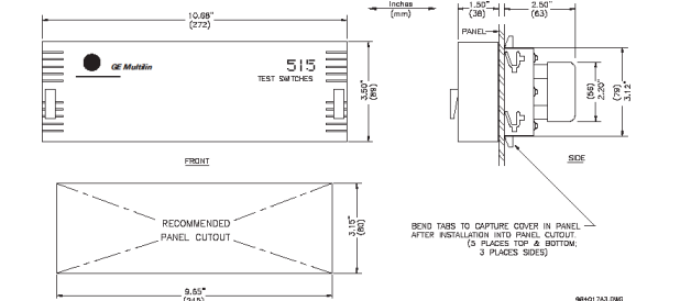
The 515 Blocking and Test Module consists of a metal chassis attached to the 515 test switches that slides into the panel. A single cutout in the panel, as per the dimensions shown in Figure 3, is required to mount the 515 test switches.
Slide the metal chassis attached to the 515 test switches into the cutout from the front of the panel. While firmly applying pressure from the front of the 515
module to ensure the chassis fits snugly, bend out the retaining tabs as shown in Figure 3. Usually the retaining tabs will be sufficient to hold the 515
module securely in place. If additional fastening is desired bend out the clamping screw tabs at both ends of the chassis at right angles. Insert the #8
screws provided in the accessory pouch into the tapped holes with the vibration proof nut between the tab and the panel. Tighten each screw until the end
of the screw butts firmly against the front panel. Ensure the nut is installed tightly against the bent tab. Nylon inserts in these nuts prevent them from
vibrating loose. The 515 test switch module should now be securely mounted to the panel with no movement ready for rear terminal wiring. When
completed, place the front cover over the mounted 515 test module and turn the fasteners at both ends ¼ turn to lock it in place, as shown in Figure 3.
As a safety precaution, a ground screw located on the bottom-right of the rear side of the module is available to be connected to panel chassis ground.
Operation
To put the 515 Blocking & Test Module into operation, additional parts have been provided:
• 1 package containing at least 28 terminal nuts
• 14 white tags for identification of each of the switches
The 515 provides a means of trip blocking, relay isolation, and testing of GE Multilin relays. The 515 accomplishes this with a total of 14 switches. There are 6
single pole throw switches for use with the output relays, and 4 groups of 2 switches each for use with the current transformers as illustrated in Figure 1:
Typical Wiring.
Isolation or opening of the relay’s output circuits is accomplished with the six switches at terminals 1 through 6 and 15 through 20.
These switches can be used to simply open the protection relay’s output contacts and thus provide a means of blocking trips. The
4 remaining groups of 2 switches at terminals 7 through 14 and 21 through 28 are used for shorting of the CT inputs, injection of
test current, and measuring of CT current. The four groups correspond to Phase 1 Current, Phase 2 Current, Phase 3 Current, and
Ground Current.
Each group is made up of two switches. The first switch for the Phase 1 group is at terminal 7 and 21 and is configured as shown
on the right:
Note that terminals 7 and 21 are shorted together regardless of whether the switch is
open or closed. The second switch for the Phase 1 group is at terminals 8 and 22. It is
configured as shown on the right:
Note that this switch operates as make before break. When this switch is closed
terminals 8 and 22 are shorted together. When this switch is open, terminals 8 and 22 open and 22 shorts with 7 and 21. This in turn shorts the
Phase 1 CT. It is essential that the CT is connected to the shorted side of the switch as shown on the right.
Otherwise, dangerously high voltages would be present at the open circuited current transformer. Also note that
currents can be injected into the protection relay from a secondary injection test set.
With the switch between terminals 7 and 21 open and the switch between terminals 8 and 22 closed as shown
below, a 515 test plug can be inserted between terminals 7 and 21 to monitor the CT current. See the diagrams
below for details. Note that the 515 test plug is made up of two conductors separated by an insulator
The GE Multilin 515 Blocking and Test Module has the following features:
• 14 Pole switchbank
• CT inputs short when current switches are opened
• Current injection for each phase
• Ground terminal
• Ability to visually isolate (open) trip relay output circuits
• Cover provided
• Suitable for utility and industrial use
• 515 test plugs available
Description
The 515 Blocking and Test Module provides an effective means of trip blocking, relay isolation and testing of GE Multilin relays. By opening the
switches and inserting test plugs, phase and residual currents from the primary CTs can be monitored. Currents can be injected into the relay from
a secondary injection test set during commissioning.
Prior to testing, the trip and auxiliary circuits must first be opened to prevent nuisance tripping; CTs can then be shorted. Conversely, when the test
is complete and the relay put back into operation, the CT switches should be closed first to ensure normal operation of the relay, prior to closing
the trip and auxiliary circuits.
Installation
Shorting switches are provided for connection of 3 phase CTs (current transformers) and a separate core balance ground fault CT or 3 phase CTs
connected for residual ground fault sensing.
When each CT switch is opened, the CT is shorted. It is essential that the CT is connected to the shorted side of the switch as shown in the following
figure, otherwise dangerously high voltages would be present from the open circuited CTs.
When the switches are open, test plugs can be inserted to either inject signals into the relay wired to the switches or monitor signals such as CT
current from the switchgear.
Figure 1: Typical wiring for connecting a 515 to a protective relay Figure 2: Typical Wiring for Zero-Sequence Ground Fault
The 515 Blocking and Test Module consists of a metal chassis attached to the 515 test switches that slides into the panel. A single cutout in the panel, as per the dimensions shown in Figure 3, is required to mount the 515 test switches.
Slide the metal chassis attached to the 515 test switches into the cutout from the front of the panel. While firmly applying pressure from the front of the 515
module to ensure the chassis fits snugly, bend out the retaining tabs as shown in Figure 3. Usually the retaining tabs will be sufficient to hold the 515
module securely in place. If additional fastening is desired bend out the clamping screw tabs at both ends of the chassis at right angles. Insert the #8
screws provided in the accessory pouch into the tapped holes with the vibration proof nut between the tab and the panel. Tighten each screw until the end
of the screw butts firmly against the front panel. Ensure the nut is installed tightly against the bent tab. Nylon inserts in these nuts prevent them from
vibrating loose. The 515 test switch module should now be securely mounted to the panel with no movement ready for rear terminal wiring. When
completed, place the front cover over the mounted 515 test module and turn the fasteners at both ends ¼ turn to lock it in place, as shown in Figure 3.
As a safety precaution, a ground screw located on the bottom-right of the rear side of the module is available to be connected to panel chassis ground.
Operation
To put the 515 Blocking & Test Module into operation, additional parts have been provided:
• 1 package containing at least 28 terminal nuts
• 14 white tags for identification of each of the switches
The 515 provides a means of trip blocking, relay isolation, and testing of GE Multilin relays. The 515 accomplishes this with a total of 14 switches. There are 6
single pole throw switches for use with the output relays, and 4 groups of 2 switches each for use with the current transformers as illustrated in Figure 1:
Typical Wiring.
Isolation or opening of the relay’s output circuits is accomplished with the six switches at terminals 1 through 6 and 15 through 20.
These switches can be used to simply open the protection relay’s output contacts and thus provide a means of blocking trips. The
4 remaining groups of 2 switches at terminals 7 through 14 and 21 through 28 are used for shorting of the CT inputs, injection of
test current, and measuring of CT current. The four groups correspond to Phase 1 Current, Phase 2 Current, Phase 3 Current, and
Ground Current.
Each group is made up of two switches. The first switch for the Phase 1 group is at terminal 7 and 21 and is configured as shown
on the right:
Note that terminals 7 and 21 are shorted together regardless of whether the switch is
open or closed. The second switch for the Phase 1 group is at terminals 8 and 22. It is
configured as shown on the right:
Note that this switch operates as make before break. When this switch is closed
terminals 8 and 22 are shorted together. When this switch is open, terminals 8 and 22 open and 22 shorts with 7 and 21. This in turn shorts the
Phase 1 CT. It is essential that the CT is connected to the shorted side of the switch as shown on the right.
Otherwise, dangerously high voltages would be present at the open circuited current transformer. Also note that
currents can be injected into the protection relay from a secondary injection test set.
With the switch between terminals 7 and 21 open and the switch between terminals 8 and 22 closed as shown
below, a 515 test plug can be inserted between terminals 7 and 21 to monitor the CT current. See the diagrams
below for details. Note that the 515 test plug is made up of two conductors separated by an insulator
out-of-step protection, rate of change of frequency, power factor, harmonic detection,
frequency out-of-band accumulation and others. An optional RTD module allows for
thermal protection and monitoring. An optional analog inputs/outputs module allows for
monitoring of generator excitation current, vibration and other parameters.
These relays contain many innovative features. To meet diverse utility standards and
industry requirements, these features have the flexibility to be programmed to meet
specific user needs. This flexibility will naturally make a piece of equipment difficult to
learn. To aid new users in getting basic protection operating quickly, setpoints are set to
typical default values and advanced features are disabled. These settings can be
reprogrammed at any time.
Programming can be accomplished with the front panel keys and display. Due to the
numerous settings, this manual method can be somewhat laborious. To simplify
programming and provide a more intuitive interface, setpoints can be entered with a PC
running the EnerVista 8 Setup software provided with the relay. Even with minimal
computer knowledge, this menu-driven software provides easy access to all front panel
functions. Actual values and setpoints can be displayed, altered, stored, and printed. If
settings are stored in a setpoint file, they can be downloaded at any time to the front panel
program port of the relay via a computer cable connected to the USB port of any personal
computer.
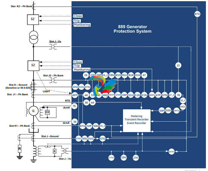
A summary of the available functions and a single-line diagram of protection and control
features is shown below. For a complete understanding of each feature operation, refer to
the About Setpoints chapter, and to the detailed feature descriptions in the chapters that
follow. The logic diagrams include a reference to every setpoint related to a feature and
show all logic signals passed between individual features. Information related to the
selection of settings for each setpoint is also provided.
Description of the 889 Generator Protection System
CPU
Relay functions are controlled by two processors: a Freescale MPC5125 32-bit
microprocessor that measures all analog signals and digital inputs and controls all output
relays, and a Freescale MPC8358 32-bit microprocessor that controls all the advanced
Ethernet communication protocols.
Analog Input and Waveform Capture
Magnetic transformers are used to scale-down the incoming analog signals from the
source instrument transformers. The analog signals are then passed through a 11.5 kHz
low pass analog anti-aliasing filter. All signals are then simultaneously captured by sample
and hold buffers to ensure there are no phase shifts. The signals are converted to digital
values by a 16-bit A/D converter before finally being passed on to the CPU for analysis.
The ‘raw’ samples are scaled in software, then placed into the waveform capture buffer,
thus emulating a digital fault recorder. The waveforms can be retrieved from the relay via
the EnerVista 8 Series Setup software for display and diagnostics.
Frequency
Frequency measurement is accomplished by measuring the time between zero crossings
of the composite signal of three-phase bus voltages, line voltage or three-phase currents.
The signals are passed through a low pass filter to prevent false zero crossings. Frequency
tracking utilizes the measured frequency to set the sampling rate for current and voltage
which results in better accuracy for the Discrete Fourier Transform (DFT) algorithm for offnominal frequencies.
The main frequency tracking source uses three-phase bus voltages. The frequency
tracking is switched automatically by an algorithm to the alternative reference source, i.e.,
three-phase currents signal if the frequency detected from the three-phase voltage inputs
is declared invalid. The switching will not be performed if the frequency from the
alternative reference signal is detected invalid. Upon detecting valid frequency on the
main source, the tracking will be switched back to the main source. If a stable frequency
signal is not available from all sources, then the tracking frequency defaults to the nominal
system frequency.
Phasors, Transients, and Harmonics
All waveforms are processed eight times every cycle through a DC decaying removal filter
and a Discrete Fourier Transform (DFT). The resulting phasors have fault current transients
and all harmonics removed. This results in an overcurrent relay that is extremely secure
and reliable and one that will not overreach.
Processing of AC Current Inputs
The DC Decaying Removal Filter is a short window digital filter, which removes the DC
decaying component from the asymmetrical current present at the moment a fault occurs.
This is done for all current signals used for overcurrent protection; voltage signals use the
same DC Decaying Removal Filter. This filter ensures no overreach of the overcurrent
protection.
The Discrete Fourier Transform (DFT) uses exactly one cycle of samples to calculate a
phasor quantity which represents the signal at the fundamental frequency; all harmonic
components are removed. All subsequent calculations (e.g. power, etc.) are based upon the
current and voltage phasors, such that the resulting values have no harmonic
components. RMS (root mean square) values are calculated from one cycle of samples
prior to filtering.
Protection Elements
All voltage, current and frequency protection elements are processed eight times every
cycle to determine if a pickup has occurred or a timer has expired. The voltage and current
protection elements use RMS current/voltage, or the magnitude of the phasor.
Security Overview
The following security features are available:
BASIC SECURITY
The basic security feature is present in the default offering of the 889 relay. The
889 introduces the notion of roles for different levels of authority. Roles are used as login
names with associated passwords stored on the device. The following roles are available
at present: Administrator, Operator, Factory and Observer, with a fixed permission
structure for each one. Note that the Factory role is not available for users, but strictly used
in the manufacturing process.
The 889 can still use the Setpoint access switch feature, but enabling the feature can be
done only by an Administrator. Setpoint access is controlled by a keyed switch to offer
some minimal notion of security.
CYBERSENTRY
The CyberSentry Embedded Security feature is a software option that provides advanced
security services. When the software option is purchased, the Basic Security is
automatically disabled.
CyberSentry provides security through the following features:
• An Authentication, Authorization, Accounting (AAA) Remote Authentication Dial-In
User Service (RADIUS) client that is centrally managed, enables user attribution, and
uses secure standards based strong cryptography for authentication and credential
protection.
• A Role-Based Access Control (RBAC) system that provides a permission model that
allows access to 889 device operations and configurations based on specific roles
and individual user accounts configured on the AAA server. At present the defined
roles are: Administrator, Operator and Observer.
• Strong encryption of all access and configuration network messages between the
EnerVista software and 889 devices using the Secure Shell (SSH) protocol, the
Advanced Encryption Standard (AES), and 128-bit keys in Galois Counter Mode (GCM)
as specified in the U.S. National Security Agency Suite B extension for SSH and
approved by the National Institute of Standards and Technology (NIST) FIPS-140-2
standards for cryptographic systems.
• Security event reporting through the Syslog protocol for supporting Security
Information Event Management (SIEM) systems for centralized cyber security
monitoring.
There are two types of authentication supported by CyberSentry that can be used to
access the 889 device:
• Device Authentication – in which case the authentication is performed on the
889 device itself, using the predefined roles as users (No RADIUS involvement).
– 889 authentication using local roles may be done either from the front panel or
through EnerVista.
• Server Authentication – in which case the authentication is done on a RADIUS server,
using individual user accounts defined on the server. When the user accounts are
created, they are assigned to one of the predefined roles recognized by the 889
– 889 authentication using RADIUS server may be done only through EnerVista.
FASTPATH: WiFi and USB do not currently support CyberSentry security. For this reason WiFi is
disabled by default if the CyberSentry option is purchased. WiFi can be enabled, but be
aware that doing so violates the security and compliance model that CyberSentry is
supposed to provide.
Enervista Viewpoint Monitor does not currently support CyberSentry security.
FASTPATH: With the CyberSentry security option, many communication settings cannot be changed
remotely. All communication settings can still be changed through the relay front panel.
When both 889 device and server authentication are enabled, the 889 automatically
directs authentication requests to the 889 device or the respective RADIUS server, based
on user names. If the user ID credential does not match one of the device local accounts,
the 889 automatically forwards the request to a RADIUS server when one is provided. If a
RADIUS server is provided, but is unreachable over the network, server authentication
requests are denied. In this situation, use local 889 device accounts to gain access to the
889 system.
USER ROLES
User Access Levels are used to grant varying permissions to specific user roles. User roles
are used by both Basic Security and CyberSentry.
The following user roles are supported:
• Administrator: The Administrator role has complete read and write access to all
settings and commands. The role does not allow concurrent access. The Administrator
role also has an operand to indicate when it is logged on.
• Operator: The Operator role is present to facilitate operational actions that may be
programmed and assigned to buttons on the front panel. The Operator has read/write
access to all settings under the command menu/section. The Operator can also use
the Virtual Input command under the control menu/section. The Operator can view
settings from EnerVista or the front panel but does not have the ability to change any
settings. This role is not a concurrent role.
• Observer: The Observer role has read-only access to all 889 settings. This role allows
concurrent access. The Observer is the default role if no authentication has been done
to the device. This role can download settings files and records from the device.
• Factory: This is an internal non-user accessible role used for manufacturing
diagnostics. The ability to enable or disable this role is a security setting that the
Administrator controls.
GENERAL RULES FOR USER ROLES WITH CYBERSENTRY
1. The only concurrent role is Observer. If the user is logged in through serial, front panel,
or over the network, that counts as the role being logged in for concurrency reasons.
2. Both EnerVista and the front panel provide a one-step logoff. For the front panel, the
root menu has a logoff command. From EnerVista right-clicking on a device and
providing a logoff function from the context menu is sufficient.
3. The EnerVista Login Screen has “User Name:” and “Password:” fields for the default
remote (Radius) authentication, but when a “Local Authentication” checkbox is
selected the “User Name:” field changes to a drop down menu where the user can
select one of the predefined roles on the 889
Must-read Information
The following general statements apply and are repeated in the relevant sections of the
manual.
FASTPATH: • WiFi and USB do not currently support CyberSentry security. For this reason WiFi is
disabled by default if the CyberSentry option is purchased. WiFi can be enabled, but be
aware that doing so violates the security and compliance model that CyberSentry is
supposed to provide.
• Before upgrading firmware, it is very important to save the current 889 settings to a
file on your PC. After the firmware has been upgraded, it is necessary to load this file
back into the 889.
• The SNTP, IRIG-B and PTP settings take effect after rebooting the relay.
• Commands may be issued freely through other protocols than Modbus (i.e., DNP, IEC
104, and, IEC 61850) without user authentication or encryption of data taking place,
even if the relay has the advanced security feature enabled.
• Note that the factory role password may not be changed.
• In 889 both DNP and IEC104 protocol can work at the same time, but consider that
there is only one point map. So, both protocols use the same configured points.
• The 52b contact is closed when the breaker is open and open when the breaker is
closed.
• The Phase Directional element responds to the forward load current. In the case of a
following reverse fault, the element needs some time – in the order of 8 ms – to
change the directional signal. Some protection elements such as Instantaneous
Overcurrent may respond to reverse faults before the directional signal has changed.
A coordination time of at least 10 ms must therefore be added to all the instantaneous
protection elements under the supervision of the Phase Directional element. If current
reversal is a concern, a longer delay – in the order of 20 ms – is needed.
• The same curves used for the time overcurrent elements are used for Neutral
Displacement. When using the curve to determine the operating time of the Neutral
Displacement element, substitute the ratio of neutral voltage to Pickup level for the
current ratio shown on the horizontal axis of the curve plot.
• If the 3-phase VT uses a delta connection and FREQUENCY INPUT is set to J2-3VT, the
positive sequence voltage is used as the supervision voltage. In such conditions, the
true supervision level is internally changed to 1/sqrt(3) of the user setting since the
base of VT here is the phase-phase voltage.
• To monitor the trip coil circuit integrity, use the relay terminals “FA_1 NO” and “FA_1
COM” to connect the Trip coil, and provide a jumper between terminals “FA_1 COM”
and “FA_1 OPT/V” voltage monitor).
• The relay is not approved as, or intended to be, a revenue metering instrument. If used
in a peak load control system, consider the accuracy rating and method of
measurement employed, and the source VTs and CTs, in comparison with the
electrical utility revenue metering system.
• In bulk oil circuit breakers, the interrupting time for currents is less than 25% of the
interrupting rating and can be significantly longer than the normal interrupting time.
• For future reference, make a printout of the conversion report immediately after the
conversion in case conversion reports are removed or settings modified from the 8
Series Setup Software.
Mechanical Installation
This section describes the mechanical installation of the 889 system, including dimensions
for mounting and information on module withdrawal and insertion.
Product Identification
The product identification label is located on the side panel of the 889. This label indicates
the product model, serial number, and date of manufacture.
Figure 2-1: Product Label
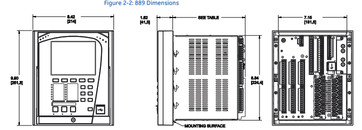
Dimensions
The dimensions (in inches [millimeters]) of the 889 are shown below. Additional dimensions
for mounting, and panel cutouts, are shown in the following sections.
Mounting
The 889 unit can be mounted two ways: standard panel mount or optional tab mounting, if
required.
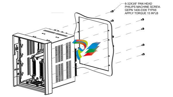
• Standard panel mounting:
From the front of the panel, slide the empty case into the cutout. From the rear of the
panel, screw the case into the panel at the 8 screw positions (see figures in Standard
panel mount section).
• Optional tab mounting:
The “V” tabs are located on the sides of the case and appear as shown in the following
figure. Use needle nose pliers to bend the retaining “V” tabs outward to about 90°. Use
caution and do not bend and distort the wall of the enclosure adjacent to the tabs. The
relay can now be inserted and can be panel wired.
Figure 2-3: “V” Tabs Located on Case Side
Standard Panel Mount The standard panel mount and cutout dimensions are illustrated below. CAUTION: To avoid the potential for personal injury due to fire hazards, ensure the unit is mounted in a safe location and/or within an appropriate enclosure. Figure 2-4: Standard panel mount
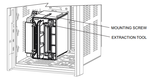
Removable Magnetic Module
IMPORTANT: Prior to the removal of the CT/VT magnetic module, all preparation steps below shall
be adhered to in order to prevent injury.
All current and voltage sources connected to the 8 Series relay must be identified
before starting the removal process.
Removal of the magnetic module from a relay installed in a power system shall only be
performed by suitably-qualified personnel.
Appropriate PPE is required based on the arc flash calculations.
CAUTION: LOTO (Lockout Tag Out) of the system is required prior to module removal/
replacement.
Follow the procedures outlined below to remove or replace the CT/VT magnetic module.
PREPARATION
1. Shut down and de-energize all systems connected to the 8 Series relay
2. Review all points in the section Cautions and Warnings.
IMPORTANT: An 8 Series relay, with the magnetic module removed, does NOT have an internal
automatic CT shorting mechanism.
CAUTION: Hazardous voltages can exist when opening the secondary circuits of live current
transformers. Make sure that in-field current transformer secondary circuits are
shorted out before making or removing any connection to the current transformer (CT)
input terminals of the device (i.e disconnection/connection of 8 Series CT Input
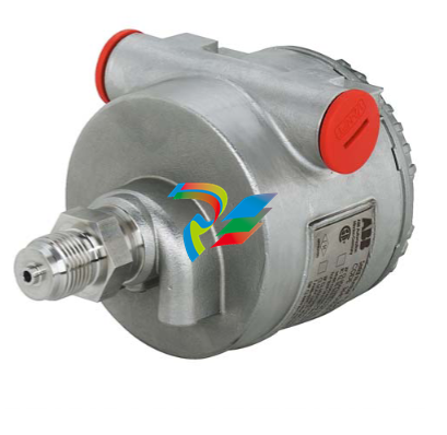
2600T Series Pressure Transmitters Models 265, 267, 269
Current limitation This electronic implements also an especial circuitry for the current limitation. Whenever a fatal failure occurs and the current consumption increase over the 19 mA, this circuitry provides a limitation of the current to 19 mA, in order to save the good functionality of the other connected devices that otherwise would be switched off due to the missing power available. 3.2 Local Display The 2000T FF Pressure Transmitter is available with an integral display as optionally item, see the Figure 1. This integral display offers the possibility to display the selected variable or diagnostic strings whenever failure and/ or warnings are detected. The variable to be displayed is user selectable among several variables produced in the TB as well as the Function Blocks output in Engineering Value, or its percentage. It is selected writing the right code in the RB_METER_OPTION. See section 8.2 in the Resource Block table. – If the transmitter works correctly, the variable selected in the RB_METER_OPTION is displayed together with the unit code, and it is updated periodically. If the value is to high to show ‘OVERFLOW’ is displayed. – When some malfunctions are detected on the display appears the following diagnostic string sequences: ‘ALARM’. The first column of the second row shows some special characters in cyclic order. This characters are the number of the shown value, write protection, transfer function, status available and EEPROM burning activ. Below the displayed value is a percent bar. The value there displayed is the OUT value of the AI1 FB at normal transmitters or the mass flow (norm volume flow) at multivariable transmitters. The display acts also as feedback of the operations performed with the external push buttons, for additional display indications see the “structure tree” Figure 3-3 on page 11.
3.3 Local Keys 3 external push buttons are available, see the Figure 2 To make the keys accessible, release the screw and turn the protection cap aside. Figure 3-2 Push Buttons View Simulation: The simulation can be activated as follows (see also symbolism on the plate). (1) First, fully press down the mode key “M” with an appropriate screw driver. 2. Then turn the switch clockwise by 90 ° angle . For deactivation the switch has to be pushed down a little and turned counterclockwise by 90 ° angle. Without display: The “-“/”+” keys have the same function like TB_SET_LOWER_RANGE and TB_SET_UPPER_RANGE. The mode ckey “M” enables/disables the simulation mode. With display: With the mode key “M”, you can start menu-controlled program-ming. To call the next menu item, press the key “+”. You will return via the key “- “. Submenu items / selection lists are acti-vated via the mode key “M”. A numerical value can only be changed via the keys “+” and ” – “. It must be taken into account that the key “+” changes the value (each keystroke increases the value by 1), whereas the position of the value to be changed is reached via the key ” – “. Acknowledge changes with the mode key “M”; the subsequent OK acknowledgement (via the key “M”, “+” or “-“) writes the new value into the failsafe storage. An ad-justing process can be aborted by pressing simultaneously the keys “+” and “-“. From any main menu item, you can return to the menu item “EXIT” by simultaneous-ly pressing the “+” and “-” keys. When the adjustment has been finished, quit the program via the menu item “EXIT”. By means of the following structure tree, you will get an overview of the selection / programming possibilities.
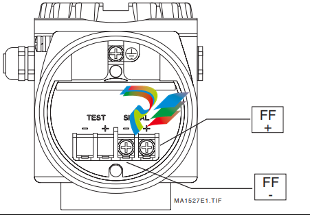
4.1 Electrical Connections The 2600 FF is a Bus Powered device with Foundation Fieldbus output. On the terminal block two screws for the BUS CONNECTION are available, see the Figure 4-4 on page 14. The Polarity has not consistency, so the two bus cables can be connected without take care about the polarity.
Device Addressing When the models 265/267/269 FF Transmitter is connected on a FF bus, the Master has to recognize it with a unique address in the world. For this reason the FF specifications define three different addressing levels that characterize the FF devices: – The DEV_ID is the unique device identifier. – The PD_TAG is the physical name of the device. – The Node Address is the real node at which the device is connected on the bus. It is automatically set by the Master (Primary LAS). The most important one with the higher priority is the DEV_ID. This is a string of 32 characters and must identify in a unique way each FF device in the world. In order to fulfill this requirement the models 265/267/269 FF applies the following mechanism: – The first part of the string is of 10 characters; the Manufacturer Code “000320” and Device Type code “0089” for 265, “008A” for 267/269. – The second part of the string is of 12 characters and represent the device type identification; “_2600T_TO___” for 265, “_2600T_MV___” for 267/269. – The third part of the string is of 10 characters and is filled with the TB_SENSOR_SERIAL_NUMBER read from the transducer database. This number is written at factory configuration stage and it is assigned in a well-defined way just to be sure to have always different numbers. Finally the DEV_ID appears of 32 characters in this way ‘0003200089_2600T_TO___xxxxxxxxxx’, where the entire ‘x’ represents the Serial number. Whenever an electronics replacement after an electronics failure is necessary, appear clear that the device will be recognized on the network as before of the replacement. This is possible because the transducer, which includes the serial number, remains unchanged and the DEV_ID will be maintained the same as before of the failure.
General 1.1. Target Group The MNS Digital Edge device is the hardware platform for ABB Ability™ Condition Monitoring for electrical systems (in the following ‘CMES’). Audiences of this manual are service technicians and switchgear operators on site. This document describes the communication and user interfaces of the MNS Digital Edge device and CMES. The reader shall be familiar with the terms and concept of ABB MNS Low Voltage Switchgear. The reader shall be familiar with the terms and concept of Microsoft Windows®.1.2. Terminology List of the terms, acronyms, abbreviations and definitions that the document uses. Abbreviation Term Description CMES Abbreviation for on-premise ABB Ability™ Condition Monitoring for electrical systems MNS Digital Edge Hardware platform for on-premise Edge computing, including CMES and cloud connectivity MNS Modular Low Voltage Switchgear family from ABB Windows OS Windows Operating System. Windows® is a registered trademark of Microsoft Corporation. All other trademarks are the property of their respective owners. 1.3. Related Documentation [1] 1TGC908002M0203 ABB Ability Condition Monitoring for electrical systems – CMES – User Manual 1.4. Related System Version The content of this document is related to MNS Digital Release 2.0 INTRODUCTION 2 1TGC908006M0202 2. Introduction This document provides an introduction on how to setup or change login credentials for the user management of the CMES. 2.1. Default settings The MNS Digital Edge is provided from ABB with the custom specific project installed. Within project specification the customer defines the number of users which have access to CMES and the respective user roles. In this case ABB will set-up the CMES with the agreed user accounts. After delivery it’s mandatory to change at least the user passwords. In case the users and roles are not defined from project, 2 default users are installed: Administrator and Operator. This is also valid when the MNS Digital Edge is ordered as spare part. Default login credentials are: Administrator User name: EdgeGwAdmin Password: PleaseChangeMe Operator User name: EdgeGwUser Password: PleaseChangeMe For cyber security reason, it’s mandatory to change the password after installation of the MNS Digital Edge. ABB will take no liability caused by using the default passwords. Please contact your IT department about details of password management and cyber security measures in your company. A process for regular update of anti-virus software needs to be implemented. By default, the Windows Defender is installed and activated. Please ensure to update the Windows OS and the anti-virus software on regular basis.
1.2. Terminology List of the terms, acronyms, abbreviations and definitions that the document uses. Abbreviation Term Description CMES Abbreviation for on-premise ABB Ability™ Condition Monitoring for electrical systems MNS Digital Edge Hardware platform for on-premise Edge computing, including CMES and cloud connectivity MNS Modular Low Voltage Switchgear family from ABB Windows OS Windows Operating System. Windows® is a registered trademark of Microsoft Corporation. All other trademarks are the property of their respective owners. 1.3. Related Documentation [1] 1TGC908002M0203 ABB Ability Condition Monitoring for electrical systems – CMES – User Manual 1.4. Related System Version The content of this document is related to MNS Digital Release 2.0 INTRODUCTION 2 1TGC908006M0202 2. Introduction This document provides an introduction on how to setup or change login credentials for the user management of the CMES. 2.1. Default settings The MNS Digital Edge is provided from ABB with the custom specific project installed. Within project specification the customer defines the number of users which have access to CMES and the respective user roles. In this case ABB will set-up the CMES with the agreed user accounts. After delivery it’s mandatory to change at least the user passwords. In case the users and roles are not defined from project, 2 default users are installed: Administrator and Operator. This is also valid when the MNS Digital Edge is ordered as spare part. Default login credentials are: Administrator User name: EdgeGwAdmin Password: PleaseChangeMe Operator User name: EdgeGwUser Password: PleaseChangeMe For cyber security reason, it’s mandatory to change the password after installation of the MNS Digital Edge. ABB will take no liability caused by using the default passwords. Please contact your IT department about details of password management and cyber security measures in your company. A process for regular update of anti-virus software needs to be implemented. By default, the Windows Defender is installed and activated. Please ensure to update the Windows OS and the anti-virus software on regular basis.
Password Complexity Rules and Password History The password has to contain characters from three of the following categories: • Uppercase letters of European languages (A through Z, with diacritic marks, Greek and Cyrillic characters) • Lowercase letters of European languages (a through z, sharp-s, with diacritic marks, Greek and Cyrillic characters) • Base 10 digits (0 through 9) • Non-alphanumeric characters (special characters): (~!@#$%^&*_-+=`|(){}[]:;”‘<>,.?/) Currency symbols such as the Euro or British Pound are not counted as special characters for this policy setting. • Any Unicode character that is categorized as an alphabetic character but is not uppercase or lowercase. This includes Unicode characters from Asian languages A new password is only accepted by Windows when it is differs from four previous passwords.
Since the MNS Digital Edge is connected to an Ethernet network it is customer’s sole responsibility to provide and continuously ensure a secure connection between the MNS Digital Edge and customer network or any other network (as the case may be). The MNS Digital Edge has following service ports open on the integrated Ethernet interfaces: Port Service Purpose 443 https / wss WEB user-interface of ABB Ability™ Condition Monitoring for electrical systems – CMES 3389 RDP Windows remote login, e.g. used for the above described user password management Customer shall establish and maintain appropriate measures (such as but not limited to the installation of firewalls, application of authentication measures, encryption of data, installation of antivirus programs, etc.) to protect the MNS Digital Edge including CMES, the network, its system and interfaces against any kind of security breaches, unauthorized access, interference, intrusion, leakage and/or theft of data or information. ABB Ltd. and its affiliates are not liable for damages and/or losses related to such security breaches, unauthorized access, interference, intrusion, leakage and/or theft of data or information.
Electrical Characteristics and Options Optional indicators Integrated digital display (code LS; only with HART standard functionality) Wide screen LCD, 128 x 64 pixel, 52.5 x 27.2 mm (2.06 x 1.07 in.) dot matrix. Two keys for zero/span or without front push buttons when ordered with R1 external pushbuttons option Display may also indicate static pressure, sensor temperature and diagnostic messages. Integral display with integral keypad (code L1; not with HART standard functionality) Wide scre
en LCD, 128 x 64 pixel, 52.5 x 27.2 mm (2.06 x 1.07 in.) dot matrix. Multilanguage. Four keys for configuration and management of device. Easy setup for quick commissioning. User selectable application-specific visualizations. Totalized and instantaneous flow indication. Display may also indicate static pressure, sensor temperature and diagnostic messages and provides configuration facilities. Integral display with Through-The-Glass (TTG) activated keypad (code L5; not with HART standard functionality) As above integral display but equipped with the innovative TTG keypad allowing the activation of the configuration and management menus of the device without the need of removing the transmitter housing cover. TTG keypad is protected against accidental activations. Optional surge protection Up to 4kV
• voltage 1.2 µs rise time / 50 µs delay time to half value
• current 8 µs rise time / 20 µs delay time to half value Process diagnostics (PILD) Plugged impulse line detection (PILD) generates a warning via communication (HART, PA, FF). The device can be configured to drive the output to “Alarm current” or set a status “BAD”. HART® digital communication and 4 to 20 mA output – Standard and Advanced functionality Device type: 1a06hex (listed with HCF) Power supply The transmitter operates from 10.5 to 42 V DC with no load and is protected against reverse polarity connection (additional load allows operations over 42 V DC). For Ex ia and other intrinsically safe approval power supply must not exceed 30 V DC. Mini
mum operating voltage increases to 12.3 V DC with optional surge protector or to 10.8 V DC with optional conformity to NAMUR NE 21 (2004). Ripple 20 mV max on a 250 Ω load as per HART specifications. Load limitations 4 to 20 mA and HART total loop resistance : A minimum of 250 Ω is required for HART communication. Output signal Two–wire 4 to 20 mA, user-selectable for linear or square root output, power of 3 /2 or 5 /2 , square root for bidirectional flow, 22 points linearization table (i.e. for horizontal or spherical tank level measurement). HART® communication provides digital process variable superimposed on 4 to 20 mA signal, with protocol based on Bell 202 FSK standard. HART revision 7 is the default HART output. HART revision 5 is selectable on request. Output current limits (to NAMUR NE 43 standard) Overload condition
• Lower limit: 3.8 mA (configurable from 3.8 to 4 mA)
• Upper limit: 20.5 mA (configurable from 20 to 21 mA) Alarm current
• Lower limit: 3.6 mA (configurable from 3.6 to 4 mA)
• Upper limit: 21 mA (configurable from 20 to 23 mA, limited to 22 mA for HART Safety; apply for electronics release 7.1.15 or later) Factory setting: high alarm current.
…Specification – electrical characteristics and options IEC 62591 WirelessHART® output Device type: 1a06hex (listed with HCF) Network ID: ABBhex (2747 decimal) Join keys: 57495245hex (1464422981) 4c455353hex (1279611731) 4649454chex (1179206988) 444b4559hex (1145783641). Power Supply 1x D-cell size lithium-thionyl chloride battery. Battery life: 10 years at 32 sec. update time, 8 years at 16 sec. update time or 5 years at 8 sec. update time. (at reference conditions of 25 ± 2 °C ambient temperature, data routed from 3 additional devices, LCD off). THE BATTERY CAN BE REPLACED IN FIELD, ALSO IN HAZARDOUS CLASSIFIED AREA. Output signal IEC 62591 WirelessHART Version 7.5 (IEEE 802.15.4-2006); Frequency band: 2.4 GHz DSSS Update rate: user selectable from 1 sec. to 60 min. Integrated adjustable omnidirectional antenna – O
utput radio frequency: maximum 10 mW (10 dBm) EIRP – Range: up to 300 m. (328 yds.) Minimum distance between antenna and person is 0.2 m. (8 in.) Telecommunications directive Every wireless measuring device must be certified in accordance with the telecommunications directive, in this case the frequency range. This certification is countryspecific. European directives Radio Equipment & Telecommunications Terminal Equipment Directive 2014/53/UE to standards EN 60950- 1:2013, EN 62311:2008, EN 301 489-1 V1.9.2, EN 301 489-17 V2.2.1, EN 300 328 v1.8.1. In Europe, use of the 2400 – 2483.5 MHz frequency band is not harmonized. Country-specific regulations must be observed. Restrictions for Norway Operation not permitted within a radius of 20 km around Ny-Alesund in Svalbard. For more information, see www.npt.no Norway Posts and T
elecommunications site Extra-european radio frequency licences USA to FCC Part 15.247:2009; Canada to IC RSS-210 and ICES-003; Argentina; United Arab Emirates (UAE); India; Mexico. PROFIBUS® PA output Device type Pressure transmitter compliant to Profiles 3.0.1 Identification number: 3450 (hex) Power supply The transmitter operates from 9 to 32 V DC , polarity independent, with or without surge protector. For Ex ia approval power supply must not exceed 17.5 V DC. Intrinsic safety installation according to FISCO model. Current consumption operating (quiescent): 15 mA fault current limiting: 20 mA max. Output signal Physical layer in compliance to IEC 1158–2/EN 61158–2 with transmission to Manchester II modulation, at 31.25 kbit/s. Output interface PROFIBUS
PA communication according to Profibus DP50170 Part 2/DIN 19245 part 1–3. Output update time 25 ms Data blocks 3 analog input, 1 physical. Additional blocks 1 Pressure with calibration transducer block 1 Advanced Diagnostics transducer block including Plugged Input Line Detection 1 Local Display transducer block Transmitter failure mode On gross transmitter failure condition, detected by selfdiagnostics, the output signal can be driven to defined conditions, selectable by the user as safe, last valid or calculated value. If electronic failure or short circuit occur the transmitter consumption is electronically limited at a defined value (20 mA approx), for safety of the network.
FOUNDATION FieldbusTM output Device type LINK MASTER DEVICE Link Active Scheduler (LAS) capability implemented. Manufacturer code: 000320hex Device type code: 0007hex Power supply The transmitter operates from 9 to 32 V DC, polarity independent, with or without surge protector. For Ex ia approval power supply must not exceed 24 V DC (FF–816 certification) or 17.5 V DC (FISCO certification). Current consumption operating (quiescent): 15 mA fault current limiting: 20 mA max. Output signal Physical layer in compliance to IEC 61158–2/EN 61158–2. Transmission to Manchester II modulation, at 31.25 kbit/s. Function blocks/execution period 3 enhanced Analog Input blocks/25 ms max (each) 1 enhanced PID block/40 ms max. 1 standard ARitmetic block/25 ms 1 standard Input Selector block/25 ms 1 standard Control Selector block/25 ms 1 standard Signal Characterization block/25 ms 1 standard Integrator/Totalizer block/25 ms Additional blocks 1 enhanced Resource block, 1 custom Pressure with calibration transducer block 1 custom Advanced Diagnostics transducer block including Plugged Input Line Detection 1 custom Local Display transducer block Number of link objects 35 Number of VCRs 35
Output interface FOUNDATION fieldbus digital communication protocol to standard H1, compliant to specification V. 1.7. Transmitter failure mode The output signal is “frozen” to the last valid value on gross transmitter failure condition, detected by selfdiagnostics which also indicate a BAD conditions. If electronic failure or short circuit occur the transmitter consumption is electronically limited at a defined value (20 mA approx), for safety of the network.
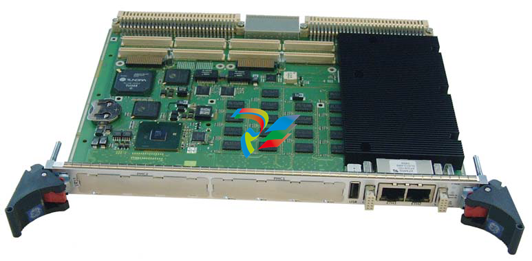
This chapter describes features, capabilities, and compatibilities of the VR12 and VP12 VME Single Board Computer (SBC). The two boards are based on the same PCB. All further occurrences of the board’s names will be referred to as the VR12. Any further specification in this document referring to VR12 can be applied to VR12 and VP12 unless otherwise noted.
The VR12 is a fully IBM®-AT compatible stand-alone PC. It is equipped with many functions a conventional Personal Computer can only offer after the installation of several add-in cards. Extension boards can be connected via the VME interface. The minimal board size and the large number of I/Os and functions allow the VR12 to be used in many applications. The VP12 is based on the VR12 but dual slot and provides with a mezzanine card two hard disk bays. The usage of PMC2 and XMC2 is limited see description of these interfaces. See the following block diagram for the boards design.
The VR12 VME Single Board Computer features: Microprocessor Intel® Core™ i5/i7 mobile processor (up to 4 MB Level3 cache) with integrated dual channel ECC Memory Controller, integrated graphic and PCIe channels Supported CPUs i7-610E 2.53 GHz 35 W SV (Standard Voltage) i5-520E 2.4 GHz 35 W SV (Standard Voltage) i7-620LE 2.0 GHz 25 W LV (Low Voltage) i7-620UE 1.06 GHz 18 W ULV (Ultra Low Voltage)
Chipset PCH Intel Series 5 Enhanced Mobile QM57 Peripheral Controller Hub (PCH) with PCIe channels, SATA, USB, graphic ports, SMBus, LPC, SPI PCIexpress Seven PCIexpress links onboard, two XMC x8 slots SDRAM onboard soldered, two 72-bit channels, 1 GB to 8 GB DDR3 1066/800 MHz with ECC SPI Flash UEFI Firmware with Back-up UEFI Firmware Easy updating, in-system programmable Flash ROM, automatic system configuration, write protected Back-up UEFI Firmware with automatic swap UEFI Firmware. Integrated VGA, SATA RAID and Ethernet PXE ROM BIOS USB mass storage support, password protection, headless support remote console via serial port EEPROM (Serial) 512 Kbit for user data via SMBus CMOS RAM 242 byte non-volatile RAM for UEFI Firmware configuration storage Hard/Flash Disk Onboard mountable 2.5” SATA (3 GB/s) hard disk or FlashDrive
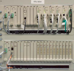
# Summary of ABB RTU560 Remote Terminal Unit ## I. Product Overview RTU560 is a Remote Terminal Unit launched by ABB, specifically designed for energy system operation. It is applicable to multiple types of energy networks, including electrical transmission and distribution networks, gas, oil, water, wastewater, and district heating grids. Its core goal is to meet monitoring, control, and communication needs in complex network environments, supporting network expansion, high availability requirements, and modernization (retrofit). Meanwhile, it achieves flexible adaptation and cost optimization through standardized protocols and modular design . ## II. Core Application Scenarios Based on modular design, RTU560 can meet three core application requirements:
### 1. Remote Control – **Core Functions**: Collect on-site data (such as switch status, analog measurements) through hardwiring and upload it to the superior control system; support remote control of on-site equipment. – **Technical Features**: Adopt a multi-processor architecture, support direct access to 110-220V DC binary I/O (no intermediate relays required), and integrate PLC functions compliant with the IEC 61131-3 standard to implement automated logic control . – **Advantages**: Suitable for cost-optimized solutions from small to large complex power stations, supporting function expansion and ensuring the safety of process control . ### 2. Communication Gateway – **Core Functions**: Simplify complex front-end communication structures,下沉 centralized communication functions to the station level, optimize bandwidth utilization, and reduce the demand for communication lines. – **Technical Features**: Support multi-protocol conversion (such as IEC 60870 series, DNP 3.0, Modbus, etc.) and adapt to TCP/IP networks and various communication media (fiber optics, radio, dial-up modems, etc.) . – **Advantages**: Improve Wide Area Network (WAN) availability, reduce data engineering costs, and support redundant configurations (communication lines, units, power supplies) to meet high availability requirements .
### 3. Station Automation – **Core Functions**: Integrate protection and control equipment, metering devices, and automation products, provide local monitoring and control capabilities, and support the transmission of disturbance records and load curves. – **Technical Features**: Integrate a Human-Machine Interface (HMI), support the IEC 60870-5-103 protocol for connecting Intelligent Electronic Devices (IEDs), and enable step-by-step retrofit of digital bay controllers . – **Advantages**: Reduce costs through unified data engineering, transmit fault data using existing communication networks, and adapt to mixed scenarios of old and new equipment .
## III. Core Advantages 1. **Flexible and Scalable System Architecture** – Modular hardware and software design support on-demand expansion of I/O, communication, and redundant configurations, adapting to networks of different scales (from small distribution stations to large complex power stations). – Adopt a multi-processor architecture (CMU boards), with internal communication ensuring data consistency, enabling distributed operation of communication tasks, and performance configurable on demand . 2. **High Reliability and Redundant Design** – Support multi-level redundancy: redundant power supplies (2×100% load), redundant communication units (CMU board active/standby switchover), and redundant communication lines (parallel or active/standby switchover mode). – Real-time monitoring of hardware and software, all modules are maintenance-free, with few types of spare parts (only 5 types of I/O modules), reducing inventory and maintenance costs . 3. **Accurate Time Synchronization and Event Recording** – Event time resolution reaches 1ms, supporting synchronization methods such as GPS, DCF77, SNTP V4, and IRIG-B, with absolute time accuracy ≤5ms (GPS/DCF77). – Can maintain a time accuracy of approximately 2ppm even after synchronization loss, ensuring the accuracy of cross-station event analysis . 4. **Powerful Communication and Protocol Compatibility** – Support multiple standard protocols: communication with control systems (IEC 60870-5-101/104, DNP 3.0, Modbus, etc.); communication with IEDs/sub-RTUs (IEC 60870-5-102/103, SPA-Bus, etc.). – Adapt to various communication media: RS 232C/485/422, fiber optics, radio, dial-up modems, TCP/IP networks, etc. . 5. **Integrated HMI and Diagnostic Functions** – Built-in HMI supports local/remote monitoring, visualizes power station status through single-line diagrams, and events and alarms can be exported to CSV format, compatible with Excel analysis. – Web server-based diagnostic functions require no dedicated tools, enabling remote access via LAN/WAN, supporting configuration checks, software upgrades, and fault analysis, reducing maintenance costs . 6. **Efficient Engineering and Programming Capabilities** – The engineering tool RTUtil 560 supports Windows systems, is compatible with Excel signal list import, simplifying large-scale data entry; follows the IEC 61346-1 standard, supporting hierarchical configuration of signals, hardware, and communication data. – Integrated PLC functions, compliant with the IEC 61131-3 standard, support 5 programming languages (FBD, LD, SFC, IL, ST), enabling sequential control or closed-loop control without additional PLC systems . ## IV. System Architecture and Hardware Design ### 1. Hardware Models and Configurations RTU560 offers three models to adapt to different scale requirements: – **RTU560A (Standard Type)**: Supports multiple communication links, with up to 2 communication subracks, suitable for large power stations (data points >1000). – **RTU560C (Compact Type)**: Supports up to 2 CMU motherboards, with I/O subracks supporting 4 peripheral bus segments, suitable for medium-sized power stations (data points 100-1000). – **RTU560E (Economic Type)**: Compact design, suitable for small power stations (data points <100), supporting centralized or distributed architectures . ### 2. Core Hardware Modules – **Communication Modules**: Include serial interface boards (560SLI02), Ethernet adapters (560ETH03), and communication units (560CMU04/80), supporting multi-protocol and redundant communication . – **I/O Modules**: Few and generalized types, including binary input/output boards, analog input/output boards, etc., supporting direct access to 110-220V DC signals (no intermediate relays required), reducing the types of spare parts . – **Power Supply Modules**: Support 24-220V DC or 110-230V AC input, redundant design (each承担 100% load), and support hot swapping . ## V. Key Technical Parameters | Category | Core Parameters | |——————-|———————————————————————————| | Processing Capacity | Supports up to approximately 3000 directly connected data points (including IED and sub-RTU data), expandable on demand. | | Time Synchronization | Event time resolution: 1ms; synchronization methods: GPS, DCF77, SNTP V4, IRIG-B; accuracy: ≤5ms. | | Communication Interfaces | Serial interfaces (RS 232C/485/422), Ethernet (10/100 BaseT), supporting fiber optic couplers. | | I/O Modules | Binary inputs: 16 channels/board (24-60V DC or 110-220V DC);<br>Binary outputs: 16 channels/board (relay output, max. 220V DC);<br>Analog inputs: 8 channels/board (accuracy <0.1%, 12-bit + sign);<br>Analog outputs: 2 channels/board (4-20mA, etc.). | | Environmental Adaptability | Operating temperature: -10~+55℃ (RTU560E: -20~+55℃); humidity: 5%~95% (non-condensing). | | Redundancy Support | Redundant power supplies, communication units (CMU), communication lines (parallel or active/standby switchover). | | Protocol Support | IEC 60870-5-101/102/103/104, DNP 3.0, Modbus, SPA-Bus, RP 570/71, etc. | ## VI. Summary RTU560 meets the diverse needs of energy systems for remote monitoring, control, and communication through modular design, multi-protocol compatibility, redundant configuration, and integrated functions. Its core values lie in: 1. **Flexibility**: Adapting to application scenarios from small and medium-scale to large complex networks, supporting step-by-step expansion and modernization. 2. **Reliability**: Redundant design and accurate time synchronization ensure high availability and reduce the risk of system interruptions. 3. **Cost-effectiveness**: Generalized hardware reduces spare part costs, and Excel integration and web diagnostics lower engineering and maintenance costs. 4. **Compatibility**: Supporting multiple standard protocols and communication media, seamlessly connecting to existing control systems and intelligent devices. RTU560 has achieved over 10,000 installations worldwide and is a key device for efficient operation of energy systems .


 1.2. Terminology List of the terms, acronyms, abbreviations and definitions that the document uses. Abbreviation Term Description CMES Abbreviation for on-premise ABB Ability™ Condition Monitoring for electrical systems MNS Digital Edge Hardware platform for on-premise Edge computing, including CMES and cloud connectivity MNS Modular Low Voltage Switchgear family from ABB Windows OS Windows Operating System. Windows® is a registered trademark of Microsoft Corporation. All other trademarks are the property of their respective owners. 1.3. Related Documentation [1] 1TGC908002M0203 ABB Ability Condition Monitoring for electrical systems – CMES – User Manual 1.4. Related System Version The content of this document is related to MNS Digital Release 2.0 INTRODUCTION 2 1TGC908006M0202 2. Introduction This document provides an introduction on how to setup or change login credentials for the user management of the CMES. 2.1. Default settings The MNS Digital Edge is provided from ABB with the custom specific project installed. Within project specification the customer defines the number of users which have access to CMES and the respective user roles. In this case ABB will set-up the CMES with the agreed user accounts. After delivery it’s mandatory to change at least the user passwords. In case the users and roles are not defined from project, 2 default users are installed: Administrator and Operator. This is also valid when the MNS Digital Edge is ordered as spare part. Default login credentials are: Administrator User name: EdgeGwAdmin Password: PleaseChangeMe Operator User name: EdgeGwUser Password: PleaseChangeMe For cyber security reason, it’s mandatory to change the password after installation of the MNS Digital Edge. ABB will take no liability caused by using the default passwords. Please contact your IT department about details of password management and cyber security measures in your company. A process for regular update of anti-virus software needs to be implemented. By default, the Windows Defender is installed and activated. Please ensure to update the Windows OS and the anti-virus software on regular basis.