General 1.1. Target Group The MNS Digital Edge device is the hardware platform for ABB Ability™ Condition Monitoring for electrical systems (in the following ‘CMES’). Audiences of this manual are service technicians and switchgear operators on site. This document describes the communication and user interfaces of the MNS Digital Edge device and CMES. The reader shall be familiar with the terms and concept of ABB MNS Low Voltage Switchgear. The reader shall be familiar with the terms and concept of Microsoft Windows®.1.2. Terminology List of the terms, acronyms, abbreviations and definitions that the document uses. Abbreviation Term Description CMES Abbreviation for on-premise ABB Ability™ Condition Monitoring for electrical systems MNS Digital Edge Hardware platform for on-premise Edge computing, including CMES and cloud connectivity MNS Modular Low Voltage Switchgear family from ABB Windows OS Windows Operating System. Windows® is a registered trademark of Microsoft Corporation. All other trademarks are the property of their respective owners. 1.3. Related Documentation [1] 1TGC908002M0203 ABB Ability Condition Monitoring for electrical systems – CMES – User Manual 1.4. Related System Version The content of this document is related to MNS Digital Release 2.0 INTRODUCTION 2 1TGC908006M0202 2. Introduction This document provides an introduction on how to setup or change login credentials for the user management of the CMES. 2.1. Default settings The MNS Digital Edge is provided from ABB with the custom specific project installed. Within project specification the customer defines the number of users which have access to CMES and the respective user roles. In this case ABB will set-up the CMES with the agreed user accounts. After delivery it’s mandatory to change at least the user passwords. In case the users and roles are not defined from project, 2 default users are installed: Administrator and Operator. This is also valid when the MNS Digital Edge is ordered as spare part. Default login credentials are: Administrator User name: EdgeGwAdmin Password: PleaseChangeMe Operator User name: EdgeGwUser Password: PleaseChangeMe For cyber security reason, it’s mandatory to change the password after installation of the MNS Digital Edge. ABB will take no liability caused by using the default passwords. Please contact your IT department about details of password management and cyber security measures in your company. A process for regular update of anti-virus software needs to be implemented. By default, the Windows Defender is installed and activated. Please ensure to update the Windows OS and the anti-virus software on regular basis.
1.2. Terminology List of the terms, acronyms, abbreviations and definitions that the document uses. Abbreviation Term Description CMES Abbreviation for on-premise ABB Ability™ Condition Monitoring for electrical systems MNS Digital Edge Hardware platform for on-premise Edge computing, including CMES and cloud connectivity MNS Modular Low Voltage Switchgear family from ABB Windows OS Windows Operating System. Windows® is a registered trademark of Microsoft Corporation. All other trademarks are the property of their respective owners. 1.3. Related Documentation [1] 1TGC908002M0203 ABB Ability Condition Monitoring for electrical systems – CMES – User Manual 1.4. Related System Version The content of this document is related to MNS Digital Release 2.0 INTRODUCTION 2 1TGC908006M0202 2. Introduction This document provides an introduction on how to setup or change login credentials for the user management of the CMES. 2.1. Default settings The MNS Digital Edge is provided from ABB with the custom specific project installed. Within project specification the customer defines the number of users which have access to CMES and the respective user roles. In this case ABB will set-up the CMES with the agreed user accounts. After delivery it’s mandatory to change at least the user passwords. In case the users and roles are not defined from project, 2 default users are installed: Administrator and Operator. This is also valid when the MNS Digital Edge is ordered as spare part. Default login credentials are: Administrator User name: EdgeGwAdmin Password: PleaseChangeMe Operator User name: EdgeGwUser Password: PleaseChangeMe For cyber security reason, it’s mandatory to change the password after installation of the MNS Digital Edge. ABB will take no liability caused by using the default passwords. Please contact your IT department about details of password management and cyber security measures in your company. A process for regular update of anti-virus software needs to be implemented. By default, the Windows Defender is installed and activated. Please ensure to update the Windows OS and the anti-virus software on regular basis.
Password Complexity Rules and Password History The password has to contain characters from three of the following categories: • Uppercase letters of European languages (A through Z, with diacritic marks, Greek and Cyrillic characters) • Lowercase letters of European languages (a through z, sharp-s, with diacritic marks, Greek and Cyrillic characters) • Base 10 digits (0 through 9) • Non-alphanumeric characters (special characters): (~!@#$%^&*_-+=`|(){}[]:;”‘<>,.?/) Currency symbols such as the Euro or British Pound are not counted as special characters for this policy setting. • Any Unicode character that is categorized as an alphabetic character but is not uppercase or lowercase. This includes Unicode characters from Asian languages A new password is only accepted by Windows when it is differs from four previous passwords.
Since the MNS Digital Edge is connected to an Ethernet network it is customer’s sole responsibility to provide and continuously ensure a secure connection between the MNS Digital Edge and customer network or any other network (as the case may be). The MNS Digital Edge has following service ports open on the integrated Ethernet interfaces: Port Service Purpose 443 https / wss WEB user-interface of ABB Ability™ Condition Monitoring for electrical systems – CMES 3389 RDP Windows remote login, e.g. used for the above described user password management Customer shall establish and maintain appropriate measures (such as but not limited to the installation of firewalls, application of authentication measures, encryption of data, installation of antivirus programs, etc.) to protect the MNS Digital Edge including CMES, the network, its system and interfaces against any kind of security breaches, unauthorized access, interference, intrusion, leakage and/or theft of data or information. ABB Ltd. and its affiliates are not liable for damages and/or losses related to such security breaches, unauthorized access, interference, intrusion, leakage and/or theft of data or information.
2600T Series Pressure Transmitters Models 265, 267, 269
Current limitation This electronic implements also an especial circuitry for the current limitation. Whenever a fatal failure occurs and the current consumption increase over the 19 mA, this circuitry provides a limitation of the current to 19 mA, in order to save the good functionality of the other connected devices that otherwise would be switched off due to the missing power available. 3.2 Local Display The 2000T FF Pressure Transmitter is available with an integral display as optionally item, see the Figure 1. This integral display offers the possibility to display the selected variable or diagnostic strings whenever failure and/ or warnings are detected. The variable to be displayed is user selectable among several variables produced in the TB as well as the Function Blocks output in Engineering Value, or its percentage. It is selected writing the right code in the RB_METER_OPTION. See section 8.2 in the Resource Block table. – If the transmitter works correctly, the variable selected in the RB_METER_OPTION is displayed together with the unit code, and it is updated periodically. If the value is to high to show ‘OVERFLOW’ is displayed. – When some malfunctions are detected on the display appears the following diagnostic string sequences: ‘ALARM’. The first column of the second row shows some special characters in cyclic order. This characters are the number of the shown value, write protection, transfer function, status available and EEPROM burning activ. Below the displayed value is a percent bar. The value there displayed is the OUT value of the AI1 FB at normal transmitters or the mass flow (norm volume flow) at multivariable transmitters. The display acts also as feedback of the operations performed with the external push buttons, for additional display indications see the “structure tree” Figure 3-3 on page 11.
3.3 Local Keys 3 external push buttons are available, see the Figure 2 To make the keys accessible, release the screw and turn the protection cap aside. Figure 3-2 Push Buttons View Simulation: The simulation can be activated as follows (see also symbolism on the plate). (1) First, fully press down the mode key “M” with an appropriate screw driver. 2. Then turn the switch clockwise by 90 ° angle . For deactivation the switch has to be pushed down a little and turned counterclockwise by 90 ° angle. Without display: The “-“/”+” keys have the same function like TB_SET_LOWER_RANGE and TB_SET_UPPER_RANGE. The mode ckey “M” enables/disables the simulation mode. With display: With the mode key “M”, you can start menu-controlled program-ming. To call the next menu item, press the key “+”. You will return via the key “- “. Submenu items / selection lists are acti-vated via the mode key “M”. A numerical value can only be changed via the keys “+” and ” – “. It must be taken into account that the key “+” changes the value (each keystroke increases the value by 1), whereas the position of the value to be changed is reached via the key ” – “. Acknowledge changes with the mode key “M”; the subsequent OK acknowledgement (via the key “M”, “+” or “-“) writes the new value into the failsafe storage. An ad-justing process can be aborted by pressing simultaneously the keys “+” and “-“. From any main menu item, you can return to the menu item “EXIT” by simultaneous-ly pressing the “+” and “-” keys. When the adjustment has been finished, quit the program via the menu item “EXIT”. By means of the following structure tree, you will get an overview of the selection / programming possibilities.
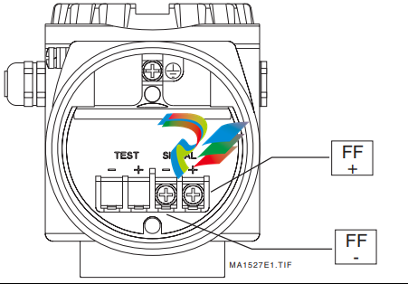
4.1 Electrical Connections The 2600 FF is a Bus Powered device with Foundation Fieldbus output. On the terminal block two screws for the BUS CONNECTION are available, see the Figure 4-4 on page 14. The Polarity has not consistency, so the two bus cables can be connected without take care about the polarity.
Device Addressing When the models 265/267/269 FF Transmitter is connected on a FF bus, the Master has to recognize it with a unique address in the world. For this reason the FF specifications define three different addressing levels that characterize the FF devices: – The DEV_ID is the unique device identifier. – The PD_TAG is the physical name of the device. – The Node Address is the real node at which the device is connected on the bus. It is automatically set by the Master (Primary LAS). The most important one with the higher priority is the DEV_ID. This is a string of 32 characters and must identify in a unique way each FF device in the world. In order to fulfill this requirement the models 265/267/269 FF applies the following mechanism: – The first part of the string is of 10 characters; the Manufacturer Code “000320” and Device Type code “0089” for 265, “008A” for 267/269. – The second part of the string is of 12 characters and represent the device type identification; “_2600T_TO___” for 265, “_2600T_MV___” for 267/269. – The third part of the string is of 10 characters and is filled with the TB_SENSOR_SERIAL_NUMBER read from the transducer database. This number is written at factory configuration stage and it is assigned in a well-defined way just to be sure to have always different numbers. Finally the DEV_ID appears of 32 characters in this way ‘0003200089_2600T_TO___xxxxxxxxxx’, where the entire ‘x’ represents the Serial number. Whenever an electronics replacement after an electronics failure is necessary, appear clear that the device will be recognized on the network as before of the replacement. This is possible because the transducer, which includes the serial number, remains unchanged and the DEV_ID will be maintained the same as before of the failure.
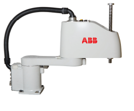
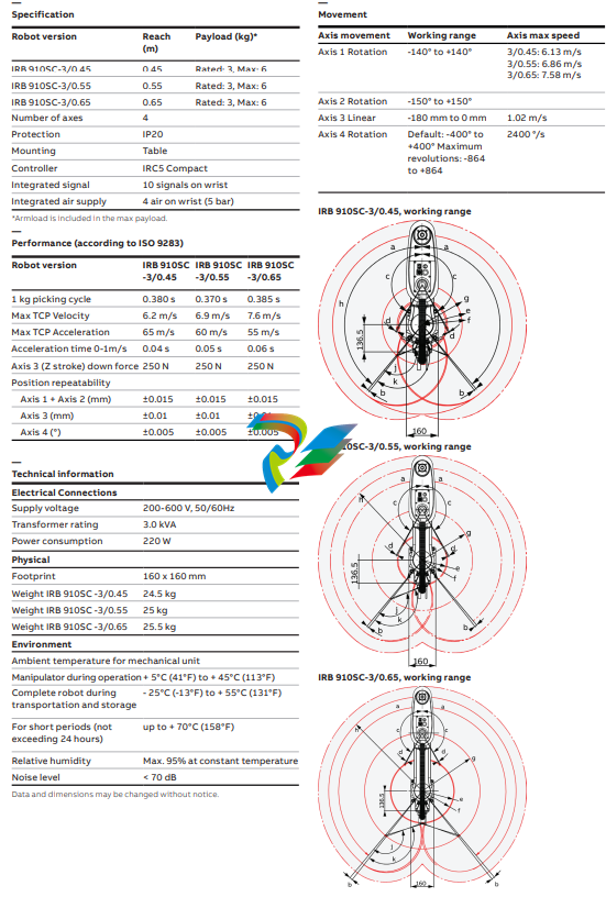
The IRB 910SC (SCARA) is fast, cost-effective and, because it‘s from ABB, accurate. In designing its Selective Compliance Articulated Robot Arm (SCARA), or IRB 910SC, ABB has delivered a single arm robot capable of operating in a confined footprint. ABB’s SCARA is ideal for the Small Parts Assembly, Material Handling and parts inspection.
ariants With a maximum payload of 6 kg, the IRB 910SC is available in three configurations (IRB 910SC –3/0.45, IRB 910SC – 3/0.55m, and IRB 910SC – 3/0.65.). All are modular by design, with different linking arm lengths and have individual reaches of 450 mm, 550 mm and 650 mm, respectively. All members of the SCARA family are tabletop mountable. Applications ABB’s SCARA family is designed for a variety of general-purpose applications such as tray kitting, component placement, machine loading/unloading and assembly. These applications require fast, repeatable and articulate point-to-point movements such as palletizing, depalletizing, machine loading/unloading and assembly. ABB’s SCARA family is ideal for customers requiring rapid cycle times, high precision and high reliability for their Small Part Assembly applications and for laboratory automation and prescription drug dispensing.
Features
• Table top mountable
• Ease of integration
• Custom interfaces
• Modular design Customer benefits
• Short cycle times which achieved by high speed
• High precision which is achieved by superior motion control
• Superb reliability due to reuse and standard proven components.
• Flexible, field-customizable 16-channel annunciator unit
• Alarm channels activated by normally open or normally closed contact
• Four +16 output relays: two for group realarms, one for an audible device, one for the self-supervision system and an additional sixteen relays for use as field contact follower outputs or group realarm outputs
• Parameter selection and adjustment from front panel or via serial interface
• First-out alarm indication with clear fourdigit display on the front panel
• Extensive data communication via the serial interface and the SPA bus
• Sophisticated hardware and software selfsupervision system for maximum operational reliability under the most demanding environmental conditions
• Powerful software support for parameterization of the unit via the serial interface
• Member of the SPACOM product family, ABB’s Distribution Automation systemt
• CE marking according to the EC directive for EMC
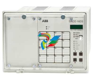
Application The digital annunciator unit is used in a variety of applications requiring supervision of alarm and signalling contacts in power plants, substations and industrial process installations. The alarm unit is also approved for use in off-shore installations and marine applications. Further, the annunciator unit can be used in any application where on/off signals are to be supervised. The annunciator unit provides immediate fault recognition, fault identification and visual and audible alarm in an abnormal process situation. The annunciator unit also provides a means for subsequent fault analyses, which means that corrective measures can be carried out without delay and full control of the process can be maintained. The annunciator units can be used either as independent stand-alone units, or they can be connected together via a fibre-optic bus to form complete supervision, event sequence reporting and data acquisition systems. The annunciator unit is a member of SPACOM, the ultimate integrated secondary equipment system for power systems.
Design The annunciator unit is composed of five modules, i.e. an alarm annunciator module, an input/output module, a connection module, an output relay module and a power module, housed in a rugged aluminium casing. The alarm annunciator module includes 16 alarm channels. The channels are activated by normally open or normally closed process contacts. The required 48 V dc contact circuit voltage is generated and supervised by the annunciator unit. Each channel can separately be assigned a start delay from 5 ms to 160 s. On activation of a channel the visual indicator of the channels starts blinking. One of five standardized blinking systems according to ISA and DIN can be selected by the operator at commissioning. The annunciator is provided with a first-out indication given via the four-digit alphanumerical display on the front panel. The firstout alarm is indicated with a letter A and the channel number. The annunciator unit is also provided with an event register, which stores the last nine events in chronological order. The event register can be read via the push-buttons and the display on the front panel or via the serial interface. The annunciator holds four output relays, two of which are used as group alarm output relays. One of five modes of operation can be selected for the realarm output relays. An additional 16 output relays are located on a separate module. These relays can be used as field contact follower outputs or as group realarm output relays. One output relay is dedicated for the selfsupervision system and one for the control of an audible device, such as a buzzer or a horn. Any information generated in the annunciator unit can be read by a hierarchically superior system via the serial interface. Data communication The annunciator unit is provided with a serial interface on the rear panel. By means of a bus connection module type SPA-ZC 17/S or SPA-ZC 21/S the unit can be connected to the fibre-optic SPA bus. The bus connection module type SPA-ZC 21/S is powered from the host unit, whereas the bus connection module SPA-ZC 17/S is provided with a built-in power unit, which can be fed from an external secured power source. The unit communicates with higher-level data acquisition and control systems over the SPA bus. Self-supervision The annunciator incorporates a sophisticated self-supervision system which increases the availability of the device and the reliability of the system. The self-supervision system continuously monitors the hardware and the software of the unit. The system also supervises the operation of the auxiliary supply module and the level of the electronics’ voltages generated by the module. If a permanent fault is detected, the fault indicator on the front panel is lit, the output relay of the self-supervision system operates and the outputs are blocked. Auxiliary supply voltage The auxiliary supply of the relay is obtained from an internal plug-in type power supply module. Two auxiliary power module types are available: type SPGU 240A1 for the supply voltage range 80…265 V ac/dc and type SPGU 48B2 for the supply voltage range 18…80 V dc. The power supply module forms the internal voltages required by the annunciator
Flexible and Reliable Device for use with all ABB Flame Detectors. The Flame Analysis Unit, or FAU810, is ABB’s latest leading-edge fl ame analysis device. The FAU810 is designed from the ground up for maximum fl exibility, usability and reliability. It takes advantage of the latest technologies available to make fl ame analysis as cost-effi cient as possible, while retaining ABB’s rock-solid reputation as the most reliable instruments in the industry. The FAU810 is easy to install and confi gure, fl exible to operate, and uses redundant Profi bus DP-V1 or standard Modbus interfaces for easy and safe data exchange and tuning. You can connect any type of ABB Flame sensing device to the FAU810. This makes the FAU810 the standard module for all ABB Flame Scanner application and the preferred solution for retrofi tting existing installation. It determines if the current signal value is within the programmed limits as defi ned by Functions. A variety of limits can be defi ned in the FAU810 to account for any situation that may occur in utility or industrial boilers.
Collects Signal Values from the Flame Detector The FAU810 analyzes the signals generated from the Flame Detector. Calculates Signal Quality The FAU810 measures the quality of the signal to provide an indication of changes in the burner flame. Quality values act as a barometer, forecasting when a burner flame-out is likely to occur. This can help you to anticipate changes and problems. Continuously Detect Faults The instrument automatically monitors the electronic components of the Flame Detector and FAU810 unit to detect system problems or faults. Signals Unsafe Conditions A no-flame condition occurs when the FAU810 logic determines that an unsafe condition exists. Remote supervisory Extended set-up, parameter fi les archiving, groups view, advanced diagnostic including fl ame raw data, real time and historical trends of up to 254 scanner heads networked is possible either through the PC based package Flame ExplorerTM or with DTM through any Profi bus DP-V1 master remote.
FAU810 Specifications Each Flame Analysis Unit consists of two independent channels. Each channel can receive and process a Flame Detector signal. The two Detectors may be in any combination of the following designs:
− SF810 Flame scanner heads
− All DFS Flame scanner heads
− Flame Rods (Ionic Flame Monitoring) Each Detector is independently configurable from the FAU810 pushbuttons and display, with Flame Explorer engineering tool or via Profibus The FAU810 can be powered by a single or redundant 24 VDC source (+/- 20%). The FAU810 has built-in diode auctioneering for power source isolation. Two digital input channels are available for remote parameter switching. One digital input per sensor. (Example: Parameters for a dedicated Flame Detector may be tailored to monitor either coal or oil firing) The FAU810 can be upgraded on site with any official release of new product features by the proprietary Firmware Download Utility
1.1 General This manual contains information of installation, operation and maintenance of the AO2000- LS25 Laser analyzer. A description of the analyzer and its basic features is also included. Please read sections 3 and 4 carefully before using the analyzer. It is a sophisticated instrument utilizing state-of-the-art electronic and laser technology. Installation and maintenance of the instrument require care and preparation. Failure to do so may damage the instrument and void the warranty.
1.2 Measuring principle The analyzer is an optical instrument for continuous in-situ gas monitoring in stack, pipes, process chambers or similar and is based on tunable diode laser absorption spectroscopy (TDLAS). The analyzer utilizes a transmitter/receiver configuration (mounted diametrically opposite each other) to measure the average gas concentration along the line-of-sight path. The measuring principle is infrared single-line absorption spectroscopy, which is based on the fact that each gas has distinct absorption lines at specific wavelengths. The measuring principle is illustrated in Figure 1-1. The laser wavelength is scanned across a chosen absorption line of the gas to be measured. The absorption line is carefully selected to avoid cross interference from other (background) gases. The detected light intensity varies as a function of the laser wavelength due to absorption of the targeted gas molecules in the optical path between transmitter and receiver. In order to increase sensitivity the wavelength modulation technique is employed: the laser wavelength is slightly modulated while scanning the absorption line. The detector signal is spectrally decomposed into frequency components at harmonics of the laser modulation frequency. The second harmonics of the signal is used to measure the concentration of the absorbing gas. The line amplitude and line width are both extracted from the second harmonics line shape, which makes the measured concentration insensitive to line shape variations (line broadening effect) caused by background gases. NOTE: The analyzer measures the concentration of only the FREE molecules of the specific gas, thus not being sensitive to the molecules bound with some other molecules into complexes and to the molecules attached to or dissolved in particles and droplets. Care should be taken when comparing the measurements with the results from other measurement techniques.
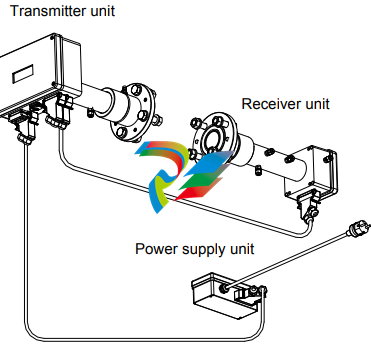
1.3 Instrument description The analyzer consists of 3 separate units (see Figure 1-2): Transmitter unit with purging
Receiver unit with purging
Power supply unit
The transmitter unit contains the laser module with a temperature stabilized diode laser, collimating optics, and the main electronics in a coated Aluminum box. The receiver unit contains a focusing lens, the photodetector and the receiver electronics in a coated Aluminum box. Both transmitter and receiver units have environmental protection IP66, and the standard optical windows withstand pressures up to 5 bar (absolute pressure). The monitor is installed by assembling the transmitter and receiver units with the supplied purging & alignment units, which in turn are mounted onto the DN50 process flanges (see Figure 3-1). The optical alignment is easy and reliable, and the purging prevents dust and other contamination from settling on the optical windows. A block diagram of AO2000-LS25 is shown in Figure 1-3. The power supply unit transforms 100-240 V AC to 24 V DC (if 24 VDC is available it can be supplied directly to the transmitter unit). The power supply box is connected to the transmitter box with a cable. The 4–20 mA input signals from external gas temperature/pressure sensors can be connected to the screw terminals inside the power box or directly to the cable connector on the transmitter unit. The receiver electronics is connected with the transmitter electronics with a cable. The detected absorption signal from the photodetector is amplified and transferred to the transmitter unit through this cable. The same cable transfers the required power from the transmitter unit to the receiver unit. The transmitter Al box contains the major part of the electronics. The CPU board performs all instrument control and calculation of the gas concentration. The main board incorporates all electronics required for instrument operation such as diode laser current and temperature control and analogue-to-digital signal conversion. A display (LCD) continuously displays the gas concentration, laser beam transmission and instrument status. The RS-232 port can be used for direct serial communication with a PC. The optional Ethernet board provides TCP/IP communication via LAN (local area network), which can be used instead of serial communication. All cable connectors are Phoenix VARIOSUB type and waterproof.
Software Software for the analyzer consists of 2 programs: 1. A program hidden to the user and integrated in the CPU electronics, running the micro controller on the CPU card. The program performs all necessary calculations and selfmonitoring tasks. 2. A Windows based program running on a standard PC connected through the RS-232 connection. The program enables communication with the instrument during installation, service and calibration. The operator will need to use the PC based program only during installation and calibration and not during normal operation of the instrument. See Section 4 for more details. 1.5 Laser classification and warnings The diode lasers used in the analyzer operate in the near infrared (NIR) range between 700 and 2400 nm depending on the gas to be measured. Laser Class 1M for sample component O2 Laser Class 1 for all other sample components according to IEC 60825-1. NOTE: The lasers emit invisible light! WARNING: Class 1M Laser Product – Do not open when energized! Do not view directly with optical instruments! WARNING: Class 1 Laser Product – Do not open when energized!
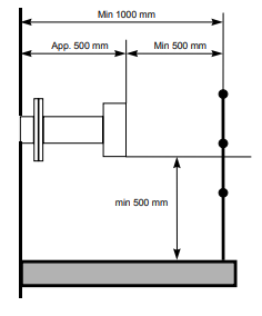
2 Preparations 2.1 Tools and other equipment The following equipment is necessary to install and calibrate the equipment: 2 pcs open-end spanners for M16 bolts 1 pcs Allen key 5 mm for the locking screws on flanges 1 pcs PC (386 or higher). Used during installation and calibration 1 pcs flat screwdriver 2.5 mm for electrical connections 2.2 Flow conditions at measuring point When deciding the placement of the analyzer in the process, we recommend a minimum of 5 stack diameters of straight duct before and 2 stack diameters of straight duct after the point of measure. 2.3 Monitor placement Both the transmitter and receiver units should be easily accessible. A person should be able to stand in front of either the transmitter unit or the receiver unit and adjust the M16 fixing bolts using two standard spanners. For the receiver unit there should be at least 1 m free space measured from the flange fixed to the stack and outwards as shown in Figure 2-1
Install transmitter alignment and purging unit (5) onto the stack flange with 4 pcs. M16x60 bolts (ref. Figure 3-4). All 4 bolts on either side must be tightened firmly to compress the large O-ring. Adjust the 4 locking screws prior to mounting the unit, to assure good alignment of the unit and a uniform compression of the O-ring. 2. Install pressurized instrument purging as described in Section 3.1.2. 3. Open the purging. Refer to Section 3.1.2 for details. 4. Put the window adapter ring (4) on the alignment unit. Make sure that the O-ring on the alignment unit is tight and greased. The guiding pin on the alignment unit must fit the hole in the adapter ring. 5. Affix an O-ring (not greased) to the adapter ring and connect the transmitter unit to the alignment unit. The guiding pin on the adapter ring must fit the hole in the transmitter window. Tighten the transmitter-mounting nut. 6. Repeat steps 1-5 for the receiver unit. 7. Connect the transmitter and receiver units with the corresponding cable (refer to Figure 6-1 for location of receiver connection on transmitter unit). All connectors are coded with small red pins on the inside. 8. Connect external 4–20 mA temperature and pressure probes (ref. Section 6.3 and 6.5). This is optional as some instruments operate without probes. Input signals are connected to the terminals in the power supply unit or directly to the terminals in the main power connector at the transmitter unit. If connected to the power connector the factory-mounted wires should be removed from the terminals in question. 9. Connect the transmitter and power supply units with the corresponding cable. The analyzer can now be switched on. This procedure is described in Section 3.2. 3.1.2 Air purging of flanges The instrument windows are kept clean by setting up a positive flow of air through the flanges and into the stack. This purging will prevent particles from settling on the optical windows and contaminating them. The purge gas must be dried and cleaned. We recommend using instrument air for purging. If instrument air is not available a separate blower is needed. A purge flow of approximately 20–50 l/min (process dependent) is sufficient for most installations. Alternatively, the initial velocity of the purge flow in the flanges is set to 1/10 of the gas velocity in the duct. After completion of the installation the purge flow is optimized as described in Section 5.3. The air quality should conform to standard set by ISO 8573.1, Class 2-3. This means particles down to 1 micron should be removed, including coalesced liquid water and oil, and a maximum allowed remaining oil aerosol content of 0.5 mg/m3 at 21C (instrument air). Note that some instruments require nitrogen purging, e.g. O2 instruments for high temperature or pressure applications, some H2O instruments etc
— Intuitive user interface and clear text prompts make installation, commissioning and operation quick and simple Scalable to match application requirements
— Comprehensive hardware and software options Flexible control functionality
— On / Off, time proportioning, analog PID and motorized valve control strategies Problem-solving capability
— Flexible functionality including math and logic providing power to solve application requirements Built to survive
— IP 66 and NEMA 4X environmental protection Flexible connectivity — Ethernet and MODBUS® communications
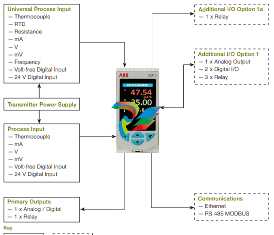
Overview The ControlMaster CM10 is a flexible, 1/8 DIN, universal PID process controller. Detailed process information is presented clearly on the CM10’s full-color TFT display and an intuitive operator interface simplifies configuration and operation. Scalable in both hardware and software functionality, a CM10 can be specified easily to meet the needs of your application requirements. Flexible control functionality including on / off, time proportioning, analog PID, split output control and math & logic make the CM10 suitable for a wide range of process applications. Fully configurable via the easy-to-navigate front panel menus or PC configuration software, the CM10 can be commissioned rapidly and then tuned via the advanced autotune functionality. MODBUS and Ethernet communication options ensure easy integration into a control system.
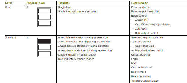
Scalable functionality The CM10 is scalable in terms of both hardware and software, enabling it to meet your application requirements. The basic CM10 meets the needs of a simple control loop. Additional templates and functionality can be enabled by adding a function key to the basic model as shown in Fig. 1, while retaining previous templates and functionality. For I/O builds, see also Ordering information on page 19
ControlMaster CM10 Universal process controller, 1/8 DIN 4 DS/CM10–EN Rev. K | ControlMaster CM10 | Universal process controller, 1/8 DIN Powerful operator display The CM10 features a full-color 5.5 cm (2.2 in.) display for displaying detailed process information to the user. Process details such as alarm messages and diagnostic information are displayed clearly in full text without the need for difficult-toread scrolling displays. Example of an operator page Automatic selection of standard display templates immediately makes best use of the CM10’s display. Extensive customization features then enable the displayed information to be tailored to suit the process requirements. Diagnostics and alarm status display The diagnostics and alarm status display provides detailed information on any active alarm or diagnostic condition. The operator can see, at-a-glance, the status of any alarm condition present within the process. Additionally, diagnostic messages are presented clearly to the operator, enabling rapid notification and simple diagnosis of any critical instrument status condition. Historical information of diagnostic messages can also be viewed in the controller’s diagnostic log.
Problem solving flexibility Extensive functionality is available to provide flexible problemsolving capability; making the CM10 much more than just a process controller. Process alarms 8 independent process alarms can monitor any analog signal within the CM10, enabling extensive process monitoring capability. Alarms can be used to drive physical outputs or soft-wired to other functions within the controller. Real-time alarms The ‘alarm clock’ functionality provided by the CM10’s realtime alarms enables time-of-day decisions to be introduced into the controller’s actions or specific functions to be triggered routinely at specified times. Delay timers Event sequencing is enabled through the use of the CM10’s delay timers. A predetermined delay and output duration can be programmed into each delay timer and timers can be linked together. Custom linearizers The CM10 has 2 independent 20-point custom linearizers that can be applied to any analog signal within the controller. These linearizers can be used in applications such as level-to-volume conversion of a non-linear tank level or to accommodate special input signals or output devices.
Math 8 math blocks provide arithmetic, averaging, min. / max. hold, square root and signal switching functionality. Simple equations can be performed in a single math block or multiple math blocks can be nested together to construct complex equations. Signal switching ‘multiplexer’ math blocks switch between 2 analog signals based on a trigger signal. For example, a backup sensor could be selected automatically on failure of a primary sensor. Logic 8 comprehensive logic equations provide powerful interlock functionality. Inputs and outputs of the logic equations can be soft-wired to any digital signal within the controller to maximize flexibility
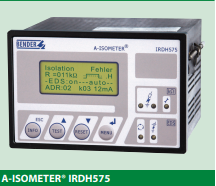
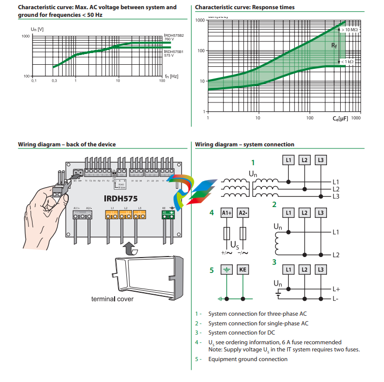
The IRDH575 monitors for ground faults in ungrounded AC (20 – 760 V, single- and threephase) and DC (20 – 575 V) by measuring the system’s insulation resistance. Systems with
extensive power conversion devices, such as rectifiers and variable frequency drives, are
supported by the IRDH575. The IRDH575 is able to detect ground faults in ungrounded
systems before leakage current may even be present.
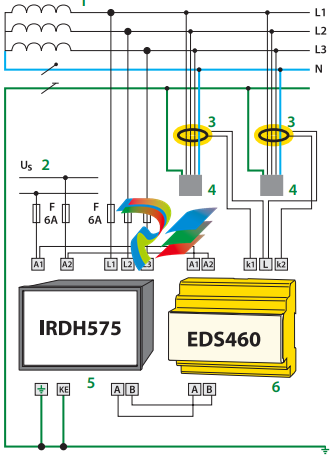
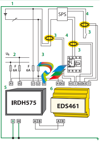
When combined with EDS4… ground fault location devices and the appropriate current
transformers, the IRDH575 becomes a controller for a ground fault location system.
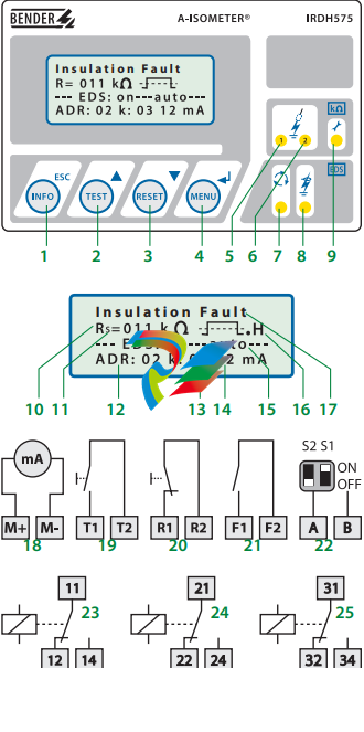
Function: Ground fault detection
When the insulation resistance from system to ground falls below the set response value,
the alarm relays switch and the alarm LEDs activate. Two separately adjustable alarm
contacts can be set to a prewarning and main warning alarm. The measured value is indicated on the LCD display or on an externally connected meter. If the device is set to nonlatching mode, the alarms will clear when the ground fault clears. If the device is set to
latching mode, the alarms will not reset until the device is reset manually or the supply
voltage is lost. An external and internal test/reset can be activated remotely or on the device. A comprehensive INFO menu key displays additional information such as the current leakage capacitance and device settings.
The IRDH575 continuously monitors the equipment ground connection and line connections to ensure proper operation. The device’s easy-to-use onboard menu manages all
settings via the detailed LCD screen.
Function: Ground fault location
When a ground fault is detected, the EDS ground fault location system is activated (this
feature can be set to require a manual start as well). Each channel of the EDS location device is connected to a particular branch circuit. The IRDH575 begins transmitting a pulsed
signal. This signal will travel through the channel of the EDS with the ground fault back
to the IRDH575. If the pulse travels back to the IRDH575, the channel with the ground
fault will display on both the IRDH575 and the EDS device.
In addition, an optional EDS30… portable ground fault location system can be used to follow the pulse travelling to the source of the ground fault.
Additional functions
99 timestamped alarm messages may be stored in the non-volatile memory of the
IRDH575. The device also includes standby contacts when several A-ISOMETER® detectors
are operating in coupled ungrounded systems.
Two-way data communication is carried out between devices via an RS-485 interface.
This interface can be connected to a BENDER protocol converter to exchange data across
other protocols, such as Ethernet, MODBUS, or PROFIBUS.
A 0/4 – 20 mA output can be connected to an external meter or higher-level control system, such as a PLC.
System design
Each isolated system requires one IRDH575 for ground fault detection and location control. Up to 90 EDS46… devices can be interconnected to the IRDH575. Each EDS device
can monitor up to 12 separate channels. An optional EDS30…. portable ground fault location system can be used in conjunction with the IRDH575/EDS46… system.
Features
• Universal application in 3(N)AC, AC/DC
and DC ungrounded systems 20…575
V/340…760 V
• Response range 1 kΩ…10 MΩ
• Info key for the indication of various
parameters and the system leakage
capacitance
• Comprehensive self-monitoring function
including system fault alarm relay
• Internal/external test and reset button
• Two separate alarm relays, operating
normally energized or normally de-energized
• Backlit LCD display
• RS-485 interface
• Data memory, system disconnection and
0/4…20mA current output
• Extendable to ground fault
location system for 1080 circuits
• Adjustable test current for ground fault
location
1 – INFO key: Displays pertinent system information
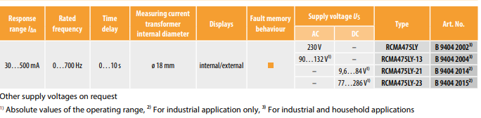
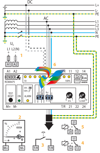
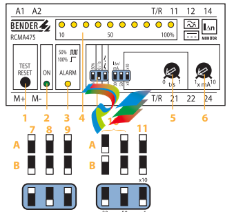
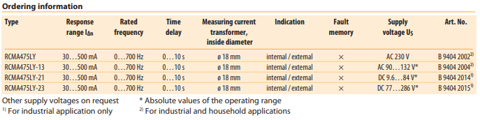
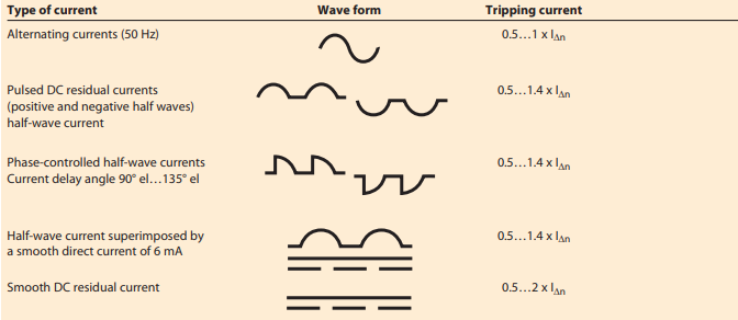
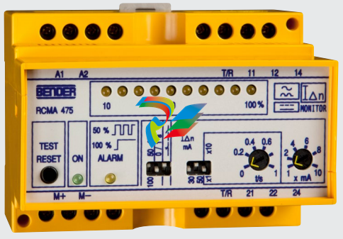
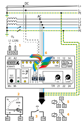
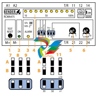
The AC / DC sensitive residual current monitor RCMA475LY is designed for monitoring earthed
power supply systems (TN and TT systems) where DC fault currents or residual currents continuously greater than zero may occur. These are in particular loads containing six-pulse
rectifiers or one way rectifiers with smoothing, such as converters, battery chargers, construction site equipment with frequency-controlled drives.
The prewarning stage (50 % of the set response value IΔn1) allow to distinguish between
prewarning and alarm. Since the values are measured with measuring current transformers,
the device is nearly independent of the load current and the nominal voltage of the system.
Application
• AC / DC sensitive residual current monitoring in earthed two, three or four conductor
systems.
• AC / DC sensitive current monitoring of single conductors de-energized under normal
 1.2. Terminology List of the terms, acronyms, abbreviations and definitions that the document uses. Abbreviation Term Description CMES Abbreviation for on-premise ABB Ability™ Condition Monitoring for electrical systems MNS Digital Edge Hardware platform for on-premise Edge computing, including CMES and cloud connectivity MNS Modular Low Voltage Switchgear family from ABB Windows OS Windows Operating System. Windows® is a registered trademark of Microsoft Corporation. All other trademarks are the property of their respective owners. 1.3. Related Documentation [1] 1TGC908002M0203 ABB Ability Condition Monitoring for electrical systems – CMES – User Manual 1.4. Related System Version The content of this document is related to MNS Digital Release 2.0 INTRODUCTION 2 1TGC908006M0202 2. Introduction This document provides an introduction on how to setup or change login credentials for the user management of the CMES. 2.1. Default settings The MNS Digital Edge is provided from ABB with the custom specific project installed. Within project specification the customer defines the number of users which have access to CMES and the respective user roles. In this case ABB will set-up the CMES with the agreed user accounts. After delivery it’s mandatory to change at least the user passwords. In case the users and roles are not defined from project, 2 default users are installed: Administrator and Operator. This is also valid when the MNS Digital Edge is ordered as spare part. Default login credentials are: Administrator User name: EdgeGwAdmin Password: PleaseChangeMe Operator User name: EdgeGwUser Password: PleaseChangeMe For cyber security reason, it’s mandatory to change the password after installation of the MNS Digital Edge. ABB will take no liability caused by using the default passwords. Please contact your IT department about details of password management and cyber security measures in your company. A process for regular update of anti-virus software needs to be implemented. By default, the Windows Defender is installed and activated. Please ensure to update the Windows OS and the anti-virus software on regular basis.
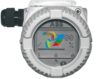

 .
.