Background and Company Performance Industry Challenges
了解年度公司如上所述,推动需求、品牌实力和竞争差异化在为客户提供独特价值方面都发挥着至关重要的作用。然而,理想情况下,这种三重关注必须辅之以同样严格的对远见创新和绩效的关注,以增强客户影响。
In 2016, the automation market was beset by several challenges, such as the plunge in oil prices, the economic slowdown in China, policy uncertainty caused by the new government in the United States, and political unrest in the Middle East. With the global investment climate improving following a rise in oil and commodity prices, there is new interest in automation projects that will boost production capacity and improve productivity. End-users are now looking for opportunities to evaluate their automation systems in light of recent advances in engineering methods, automation, and the connectivity provided by commercial information technology and the Industrial Internet of Things (IIoT), rather than simply returning to the methodologies of the past such as upgrading to the latest version of a control system provided by the current automation vendor
The process industries’ production assets have never been larger or more complicated, and with increased scale and complexity, there is a growing inability to predictably deliver capital projects on schedule and within budget. In this scenario, the primary concern of the end-users lies in deploying their resources in a cost-effective way and attaining high capital efficiency. This cannot be achieved by just squeezing prices. It requires new methods of executing projects and new ways of looking at things. The attempt to reduce project costs adds pressure to automation costs, which is a prime challenge to the growth of Distributed Control System (DCS) vendors. DCS vendors that address this challenge through the use of innovative technologies in the field of cloud engineering, digital marshaling, virtualization, and automated data management are expected to gain a competitive advantage
The process industries’ production assets have never been larger or more complicated, and with increased scale and complexity, there is a growing inability to predictably deliver capital projects on schedule and within budget. In this scenario, the primary concern of the end-users lies in deploying their resources in a cost-effective way and attaining high capital efficiency. This cannot be achieved by just squeezing prices. It requires new methods of executing projects and new ways of looking at things. The attempt to reduce project costs adds pressure to automation costs, which is a prime challenge to the growth of Distributed Control System (DCS) vendors. DCS vendors that address this challenge through the use of innovative technologies in the field of cloud engineering, digital marshaling, virtualization, and automated data management are expected to gain a competitive advantage
ABB aligns with market Mega Trends and develops industry-specific DCS solutions to address the demands of different end-user market segments. ABB’s product solution targets Mega Trends such as Urbanization and Innovation to Zero across the end-user industries, enabling them to create new opportunities and values for their customers. This has helped ABB to stay ahead of competition and retain a leadership position in the DCS market. With market growth drivers such as increasing demand to implement advanced control strategies, the need for software-based services, value-added services (including upgrading cyber security, consulting, and training), and optimizing lifecycle costs are
expected to be intact in the short term. ABB is well positioned to retain its leadership position in the future as it is primed to deliver value to its clients in this market.
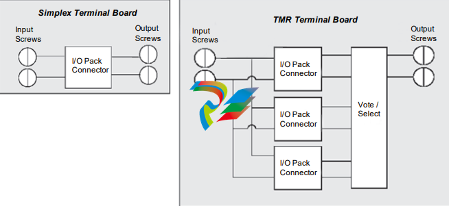
Addressing Unmet Needs The increasing scale and complexity of automation projects has made it almost impossible to deliver capital projects on schedule and within budget. A key contributor to the growing risk of missing DCS project deadlines include late design changes, which tend to cascade throughout a project. A significant unmet need in the market is decreasing the dependency of the automation design on the process design. ABB took a significant step forward in streamlining the execution of its customers’ automation projects with the release of its Select I/O, an Ethernet-based single channel I/O solution for the ABB Ability™ System 800xA. This can be configured in the field to address the growing demand for full redundancy down to the signal conditioning module. Because the base hardware for every type of signal is the same, Select I/O effectively allows each I/O channel to remain flexible and “undeclared” until very late in the project, often up until just before commissioning. This effectively decouples I/O hardware engineering from software design, which lowers development costs and shortens the delivery schedule. The Select I/O, when coupled with the process know-how of ABB, improves the efficiency of DCS project execution and provides ABB a distinctive advantage in the DCS market with respect to competition.
Visionary Scenarios through Mega Trends The concept of a connected industry is increasingly becoming a reality as industries, such as oil and gas, chemicals, power, pharmaceuticals, steel, water, mining, food, and beverage, move towards a digital operating environment to improve connectivity, productivity, and cost-effectiveness. The recent launch of the ABB Ability platform in 2017 will provide ABB with a competitive edge over its competitors because it provides unified, cross-industry digital capability—extending from device to edge to cloud—with devices, systems, solutions, and services. While similar competitor offerings allow end-users to sense, analyze, and take actions to drive efficiency, ABB has added self-learning capabilities to its solution that allow it to harvest data, take control, and enable users to do more. This distinguishes ABB from the rest of the competition in the market.
Implementation of Best Practices Through its Next Level Strategy, which aims at profitable growth, relentless execution, and business-led collaboration, ABB has adapted to rapidly changing market dynamics to serve its clients with a combined power and automation portfolio. In October 2016, it launched its Stage 3 of the Next Level Strategy, which helps ABB rebuild its successful
transformation momentum and strengthen its position as a pioneering technology leader and global digital champion. ABB places a high focus on increasing its customer value proposition with the help of software-led differentiation, solutions-as-a-service, and technology leadership.
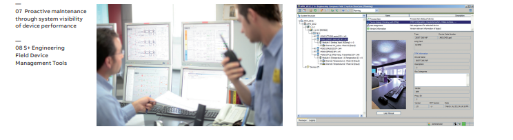
ABB’s dedicated service organization focuses on maintaining and continuously improving the performance of customer’s equipment and processes through a suite of services. Especially ABB’s advanced digital services are in continuous evolution, also in combination with new business models, to address opportunities through digitalization and unmet needs of customers. A key differentiator for ABB is its lifecycle policy. This policy aims at maximizing the useable life of a customer’s investment. This means that ABB is committed to maintaining full lifecycle integrity for its products and systems and supports any products for at least 10 years once removed from active sale and an equivalent replacement is available. In order to take complete advantage of digital transformation, a broader ecosystem of applications is required. For instance, start-ups foster innovation and help automation vendors scale up their digital offerings faster than they would with organic developments. As a leading automation vendor, ABB embraced this trend earlier than many other vendors in the automation space. ABB formed a strategic venture capital unit called the ABB Technology Ventures (ATV) in 2009. ATV focuses on many segments and automation is one core focus area for the organization. The primary objective is to seek out potential automation technology partners who are aligned seamlessly with ABB’s vision of industrial digitalization. Since its inception, ATV has invested about $150 million in technology companies that have a high potential in diverse sectors, including IIoT and cybersecurity. These start-ups function as an extension of ABB and offer innovative services and analytics capabilities to complement its existing digital portfolio. In October 2016, ABB entered into a strategic partnership with Microsoft to develop next-generation digital solutions on an integrated cloud platform that will enable digital transformation for its customers in businesses such as robotics, marine, and eMobility.
Financial Performance ABB’s penetration and expansion in emerging markets has helped it dominate the DCS market with a 20.5% market share in 2016 and continue its market dominance, while its two closest competitors hold market shares in the range of 15.2% and 14.5%. ABB has unswervingly lead the DCS market across power end-user segment. It’s expertise in developing innovative solutions that match the needs of energy and energy-intensive industries like oil and gas, utilities, and mining operations has reinforced its significant global market share. ABB has the best and widest DCS portfolio across the process automation market. The organization offers the customer-specific control platforms ABB Ability System 800xA, ABB Ability Symphony Plus, Freelance and a Compact Product Suite. ABB’s continued quench to stay ahead of the market is very clear here, as its competitors are progressively introducing compact and low-cost products in the years to come from now. While many competitors have had flat growth in recent years, ABB continues to steam ahead and build on its existing installed base. For instance, in the oil and gas enduser industry where safety is a primary concern, ABB astutely developed the System 800xA HI (High Integrity) solution. This integrates two previously independent automation platforms— safety and process control—into a single system. Also, with rising concerns over minimizing the carbon footprint, ABB has given its clients a greater visibility of energy use with the help of more integrated
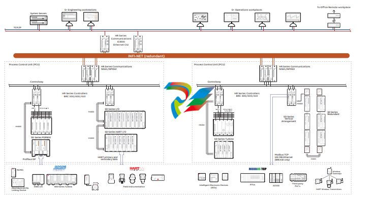
assistance 24/7. Problems are solved before they become failures by utilizing data insights and advanced analytics and through remote collaboration that enables real-time customer interaction. With two DCS product lines – ABB Ability System 800xA and ABB Ability Symphony® Plus – ABB addresses the specific needs of various industries. Both DCS solutions are industryleading and proven over decades evident by their installed base. Symphony Plus is tailored to the power generation and water industries whereas System 800xA is targeted towards all other industries. Both solutions support customers by driving gains in performance, productivity, efficiency, and safety throughout the end-user business operations lifecycle, from the planning stage to the maintenance stage. With the help of domain expertise and process knowledge, ABB has developed an overarching digital architecture that augments the human expertise of the clients to deliver improved performance. ABB also has a footprint across a broad range of industry verticals, more than any other participant in the industrial space. ABB’s years of domain expertise, combined with its huge installed base, distinguishes it from other automation vendors in the Global DCS market. Further, it enables ABB to design its solutions based on the context of each end-user requirement.
Customer Service Experience In line with its growth strategy, ABB extends its expertise and resources into key target markets such as power generation, oil and gas, and metals and mining, where process automation systems have significant growth opportunities in both greenfield and brownfield projects. The ABB Value Provider Program (VPP), a one-of-its-kind program in the market, is aimed at developing ABB’s third-party channels including distributors, technical distributors, system integrators, panel builders, and service providers. With the help of this program, ABB locates a third-party provider in close proximity to its end-users in order to reduce the response time to its clients’ sales, support, service, and engineering needs. The value provider’s in-depth knowledge about local markets coupled with an expertise in ABB’s products enables it to function as an extension of ABB, resulting in extensive coverage in targeted regional segments. ABB has leveraged its decades of experience in the DCS market to develop the capability of a Main Automation Contractor (MAC). This means that ABB can offer a wider scope than conventional vendors by working proactively with clients to deliver a complete automation solution, from automation/instrumentation selection to commissioning and after-sales support. This helps end-users reduce the project schedule, engineering required, and change requests. Also, with the introduction of Ability, ABB is well qualified to deliver turnkey Main Automation, Electrical and Information Contractor (MAEIC) solutions. Only one other company, apart from ABB can deliver a similar solution. This is another critical differentiating factor for ABB.
Conclusion ABB equips industrial customers with the digital technology and cloud platform to empower every person, team, and business system within an organization to glean new insights and drive smarter, faster and simpler decision-making—thereby helping every customer seize new growth opportunities. By offering ultimate flexibility in the field, ABB sets a new standard in the execution of automation projects. ABB will continue to stay ahead of developments in the DCS market because it takes inspiration directly from evolving customer needs and industry standards. Continuing its decades of innovation history, ABB is a pioneering leader in DCS market and leads the digitalization of the energy industry. With its strong overall performance, ABB is recognized with Frost & Sullivan’s 2017 Company of the Year Award.
Conclusion ABB equips industrial customers with the digital technology and cloud platform to empower every person, team, and business system within an organization to glean new insights and drive smarter, faster and simpler decision-making—thereby helping every customer seize new growth opportunities. By offering ultimate flexibility in the field, ABB sets a new standard in the execution of automation projects. ABB will continue to stay ahead of developments in the DCS market because it takes inspiration directly from evolving customer needs and industry standards. Continuing its decades of innovation history, ABB is a pioneering leader in DCS market and leads the digitalization of the energy industry. With its strong overall performance, ABB is recognized with Frost & Sullivan’s 2017 Company of the Year Award.


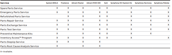
 Services portfolio
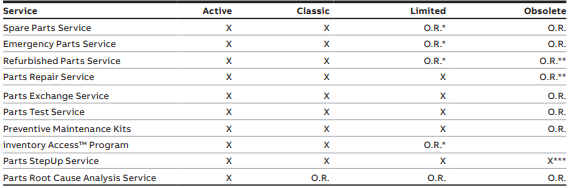 * Stock dependant – ABB stocks sufficient inventory at the end of the Classic phase to support anticipated demand during the Limited phase. The available inventory level is one of the criteria used to determine the timing for transfer to the Obsolete phase. ** Component availability dependant – ABB will continue to provide repair services until it is no longer technically feasible to do so due to the lack of component availability. *** Only available for Advant Master and Advant MOD 300