Call us 24/7+86 15396210640
Welcome to the official website of Lingkong Automation Technology Co., Ltd!
Call us 24/7+86 15396210640

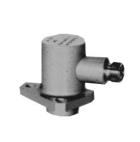
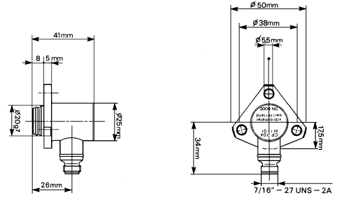
STOBERDESCRIZIONE Il regolatore indicatore Serie SG65 è adatto al controllo di variabili fisiche quali temperatura, pressione e livello di liquidi, gas e vapori negli impianti industriali o di processo. Il valore misurato della variabile fisica viene

This manual contains information which must be adhered to in order to prevent personal 

injury and property damage. This information is graduated by degree of damage as 

shown below. 

ATTENTION 

Means that an undesired result or undesired state may occur if this note is not heeded.

CAUTION 

Without warning triangle: Means that property damage may occur if appropriate 

precautions are not taken. 

CAUTION 

With warning triangle: Means that minor personal injury and property damage may occur 

if appropriate precautions are not taken. 

WARNING 

Means that major danger of death and substantial property damage may occur if 

appropriate precautions are not taken. 

DANGER 

Means that great danger to life and substantial property damage will occur if appropriate 

precautions are not taken. 

NOTE 

Indicates an important piece of information on the product or the drawing of attention to a 

part of the documentation requiring special attention. 

ACTION 

Means the description of an action which is particularly important for handling the 

product.

WARNING 

To ensure that avoidable problems do not occur during commissioning and/or operation, 

be sure to read these installation and commissioning instructions before installation and 

commissioning. 

In the sense of DIN EN 50178 (formerly VDE 0160), the FDS and MDS model series of 

POSIDRIVE®

 are electrical components of power electronics for the regulation of energy 

flow in high-voltage systems. They are exclusively designed to power servo (MDS) and 

asynchronous (FDS, MDS) machines. Utilization, installation, operation and maintenance 

are only permitted under observation and adherence to valid regulations and/or legal 

requirements, applicable standards and this technical documentation. 

This is a product of the restricted sales class in accordance with IEC 61800-3. In a 

residential zone, this product may cause high-frequency interference in which case the 

user may be requested to take suitable measures. 

 Strict adherence to all rules and regulations must be ensured by the user. 

The safety notes contained in further sections (items) and specifications must be 

adhered to by the user. 

WARNING 

Caution! High touch voltage! Danger of shock! Danger to life! 

When network voltage is applied, never under any circumstances open the housing or 

disconnect the connections. When installing or removing option boards, you may only 

open the inverter in the dead state (all power plugs disconnected) and only after a 

waiting period of at least 5 minutes after the network voltage is switched off. Prerequisite 

for the correct functioning of the inverter is the correct configuration and installation of 

the inverter drive. Transport, installation, commissioning and handling of the device may 

only be performed by qualified personnel who have been especially trained for these 

tasks. 

Pay particular attention to the following: 

• Permissible protection class: Protective ground. Operation is only permitted when the 

protective conductor is connected in accordance with regulations. Direct operation of 

the devices on IT networks is not possible. 

• Installation work may only be performed in the dead state. For work on the drive, lock 

enable and disconnect the complete drive from the power. (Observe the 5 safety 

rules.) 

• Leave the plug for the DC link coupling connected even when the DC link coupling is 

not being used (BG0-BG2: X22)! 

• Discharge time of the DC link capacitors > 5 minutes. 

• Do not penetrate the device’s interior with any kind of object. 

• During installation or any other work in the switching cabinet, protect the device 

against falling parts (pieces of wire, stranded wire, pieces of metal, and so on). Parts 

with conductive properties may cause a short circuit within the inverter or device 

failure. 

• Before commissioning, remove extra coverings so that the device cannot overheat. 

The inverter must be installed in a switching cabinet in which the maximum ambient 

temperature (see technical data) is not exceeded. Only copper lines may be used. The 

line cross sections to be used are contained in table 310-16 of the NEC standard at 

60 o

C or 75 o

C. 

The company STÖBER ANTRIEBSTECHNIK GmbH + Co. KG accepts no liability for 

damages resulting from non-adherence to the instructions or the particular 

regulations. 

The motor must have an integral temperature monitor with basis insulation as per 

EN 61800-5-1 or external motor overload protection must be used. 

Only suitable for use on supply current networks which cannot deliver more than a 

maximum symmetric, nominal, short-circuit current of 5000 A at 480 Volt. 

Integral solid state short circuit protection does not provide branch circuit protection. 

Branch circuit protection must be provided in accordance with the Manufacturer 

Instructions, National Electrical Code and any additional local codes”, or the equivalent. 

Suitable for use on a circuit capable of delivering not more than 10 kA rms. Symmetrical 

Amperes, 480 Volts Maximum” when Protected by RK1 Class Fuses as specified in the 

chapter technical data. 

 Subject to technical changes without prior notification which changes serve to 

improve the devices. This documentation is purely a product description. It does 

not represent promised properties in the sense of warranty law. 

1.2 Software 

Use of the POSITool software The POSITool software package can be used to select an application, adjust parameters 

and signal monitoring of the 5th generation of STÖBER inverters. The functionality is 

specified by the selection of an application and the transmission of these data to an 

inverter. 

The program is the property of STÖBER ANTRIEBSTECHNIK GmbH + Co. KG and is 

protected by copyright. The program is licensed for the user. 

The software is provided exclusively in machine-readable format. 

The customer receives from STÖBER ANTRIEBSTECHNIK GmbH + Co. KG a nonexclusive right to use the program (license) if the program was obtained legally. 

The customer has the right to utilize the program for the above stated activities and 

functions and to make and install copies of the program, including one backup copy, for 

support of said utilization. 

The conditions of this license apply to all copies. The customer is obligated to place the 

copyright note and all other ownership notes on every copy of the program. 

The customer is not authorized to use, copy, change or pass on/transmit the program for 

reasons other than those covered by these conditions; the customer is also not 

authorized to convert the program (reverse assembly, reverse compilation) or compile 

the program in any other manner, or to sublicense, rent or lease the program. 

Product maintenance The obligation to perform maintenance applies to the two last current program versions 

prepared and released for use by STÖBER ANTRIEBSTECHNIK GmbH + Co. KG. 

STÖBER ANTRIEBSTECHNIK GmbH + Co. KG can either correct program errors or 

provide a new program version. The choice is up to STÖBER ANTRIEBSTECHNIK 

GmbH + Co. KG. If, in individual cases, the error cannot be corrected immediately, 

STÖBER ANTRIEBSTECHNIK GmbH + Co. KG will provide an intermediate solution 

which, if necessary, requires adherence by the user to special operating regulations. 

The claim to error correction only exists when reported errors are reproducible or can be 

recorded by machine-made outputs. Errors must be reported in reconstructable form 

giving useful information for error correction. 

The obligation to correct errors is invalidated for such programs which the customer 

changes or manipulates unless the customer can prove when reporting the error that the 

manipulation is not the cause of the error. 

STÖBER ANTRIEBSTECHNIK GmbH + Co. KG is obligated to keep the currently valid 

program versions in a specially protected place (fire-resistant data safe, safety deposit 

box at a bank). 

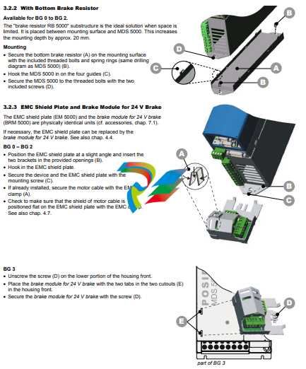
3.2.2 With Bottom Brake Resistor 

Available for BG 0 to BG 2.

The “brake resistor RB 5000” substructure is the ideal solution when space is 

limited. It is placed between mounting surface and MDS 5000. This increases 

the mounting depth by approx. 20 mm. 

Mounting 

• Secure the bottom brake resistor (A) on the mounting surface 

with the included threaded bolts and spring rings (same drilling 

diagram as MDS 5000) (B). 

• Hook the MDS 5000 in on the four guides (C). 

• Secure the MDS 5000 to the threaded bolts with the two 

included screws (D). 

3.2.3 EMC Shield Plate and Brake Module for 24 V Brake 

The EMC shield plate (EM 5000) and the brake module for 24 V brake 

(BRM 5000) are physically identical units (cf. accessories, chap. 7.1). 

If necessary, the EMC shield plate can be replaced by the 

brake module for 24 V brake. See also chap. 4.4. 

BG 0 – BG 2 

• Position the EMC shield plate at a slight angle and insert the 

two brackets in the provided openings (B). 

• Hook in the EMC shield plate. 

• Secure the device and the EMC shield plate with the 

mounting screw (C). 

• If already installed, secure the motor cable with the EMC 

clamp (A). 

• Check to make sure that the shield of motor cable is 

positioned flat on the EMC shield plate with the EMC clamp. 

See also chap. 4.7. 

BG 3 

• Unscrew the screw (D) on the lower portion of the housing front. 

• Place the brake module for 24 V brake with the two tabs in the two cutouts (E) 

in the housing front. 

• Secure the brake module for 24 V brake with the screw (D)

Installation of Accessories 

Only specialized personnel who are qualified for this task may install accessories (cf. chap. 7). Suitable measures must be 

provided against damage by electrostatic discharging (in accordance with DIN EN 50082-2). Before installation, the device must 

be disconnected from the power and, with the MDS 5xxx/L series, the 24 V power must be turned off. Remember the discharge 

times (≥ 5 min.) for the DC link. 

CAUTION 

Immediately after the power is turned off, the DC link is still charged. Wait > 5 min. for the DC link to discharge 

after turning off the power voltage. To prevent damage to device and accessory parts, install the accessory 

afterwards. 

CAUTION 

Danger of electrostatic charges damaging the PCB! 

Perform potential equalization before you touch a PCB (option module 1 and 2). 

3.3.1 Option module 1 (fieldbus) 

3.3.1.1 CANopen DS-301 (CAN5000) / PROFIBUS DP-V1 (DP5000) 

Installation is the same for both modules. 

• Make sure that the device is without power. Wait ≥ 5 min. for the DC link capacitors to discharge after turning off the power 

supply voltage. 

• Disconnect the cover plate by removing the two screws (E). 

• Remove the prepunched area (A) for the sub D plug connector on the plate. 

• Mount the plate on the board with the included UNC bolts (B). 

• Slide the fieldbus board (C) with the gold-contacted terminal surfaces (D) into the black terminal block. 

CAUTION 

Be sure not to touch the gold contact surface with your fingers (danger of fouling and corrosion). 

• Check correct position of the board. 

• Secure the board with the two included screws (E). 

• Then apply included labels (nameplate and adhesive label for switch setting (CAN)) to the cover plate. 

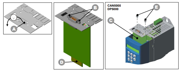
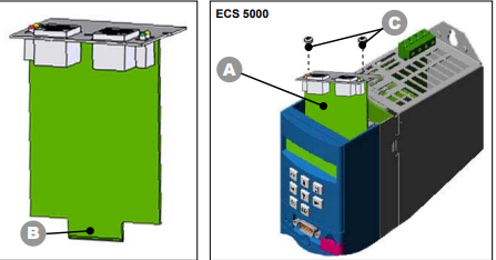
3.3.1.2 EtherCAT (ECS 5000) 

• Make sure that the device is without power. Wait ≥ 5 min. for the DC link capacitors to discharge after turning off the power 

supply voltage. 

• Disconnect the cover plate by removing the two screws (C). 

• Slide the EtherCAT board (A) with the gold-contacted terminal surfaces (B) into the black terminal block. 

CAUTION 

Be sure not to touch the gold contact surface with your fingers (danger of fouling and corrosion). 

• Check correct position of the board. 

• Secure the board with the two included screws (C). 

• Then apply included labels (nameplate) to the cover plate.

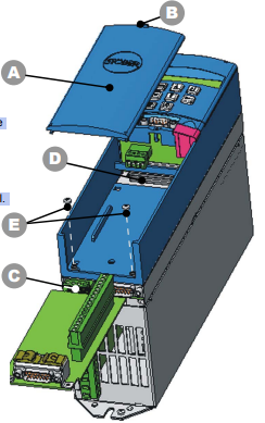
3.3.2 Option module 2 (terminals) 

• Standard (SEA 5000, SEA 5001) 

• Expanded (XEA 5001) 

• Resolver (REA 5000)

Installation is the same for all modules. 

• Make sure that the device is without power. 

• Before installation, remove the blue plastic cover (A) below the serial interface 

(terminal X3). 

• Make sure that the device is without power. 

• Unlock the snap-on lock (B) directly below terminal X3 and, on the snap-on 

lock, pull the cover towards the front. 

• To completely unhook the cover, pull this in the direction of the operator panel. 

• Push the I/O terminal module with the gold-contacted terminal surface (C) 

into the black terminal block (D). 

CAUTION 

Be sure not to touch the gold contact surface with your fingers 

(danger of fouling and corrosion). 

• Check correct position of the board. 

• Secure the board with the two included screws (E). 

• Now hook the plastic cover (A) with the two catches into the plastic housing. 

• Press the plastic cover (A) against the plastic housing until the snap-on lock 

(B) snaps in. 

POSIDRIVE® MDS 5000 – Mounting Instructions STÖBER ANTRIEBSTECHNIK 

4. Electrical Installation 

15

4 ELECTRICAL INSTALLATION 

This chapter gives you complete information on the subject of electrical installation. 

Only specialized personnel who are qualified for this task may install, commission and control the device. 

4.1 EMC 

This chapter contains general information on EMC-suitable installation. These are only recommendations. Depending on the 

application, the ambient conditions and the legal requirements, measures in addition to the following recommendations may be 

required. 

• Mount device or Bottom Brake Resistor on conductive surface (unpainted). 

• Install the power cables in spatially separately from the signal lines (encoder, analog/digital signal lines). 

• Use only shielded cable for motor lines (corresponding cabels can be ordered from STÖBER ANTRIEBSTECHNIK.). 

• Apply shield of the motor cable over a large surface in the immediate vicinity of the MDS 5000. The EMC shield plate (EM 

5000) for mounting on the bottom of the device is available as an accessory (see chap. 3.2.3 and chap. 7.1). 

• With asynchronous machines, apply the shield to the terminal block over a large surface (e.g. PG shield screw connection). 

• Use output deraters for motor lines > 50 m. 

• When an additional transfer plug connector is to be installed in the motor cable, the cable shield may not be interrupted. 

• When the brake line is installed in the motor cable, the brake line must be shielded separately. 

• When the length of the cable for connection of a brake resistor is longer than 30 cm, this must be shielded and the shield 

must be applied over a large surface in the immediate vicinity of the MDS 5000. 

• Connect the shield of the control lines on one side with reference ground of the reference value source (e.g., PLC or CNC). 

• Shield, and, if necessary, twist reference value lines before installing. 

4.2 RCD (Residual Current Protective Devices) 

Network phases and neutral conductors are connected with the protective conductor via Y capacitors. When network voltage is 

applied, a leakage current flows over these capacitors to the protective conductor. The greatest leakage current occurs during a 

malfunction (asymmetric feedin via only one phase) and during power-on (sudden change in voltage). The maximum leakage 

current due to asymmetric power feedin is 40 mA (network voltage of 400 V) for MDS inverters. 

If RCD circuit breakers are necessary, the problem of power-on and off can be alleviated by using selective RCD circuit 

breakers (switch-off delay) or RCD circuit breakers with increased tripping current (e.g., 300 or 500 mA). Only all-current 

sensitive RCD circuit breakers may be used. Operation of several devices on one RCD circuit breaker is not recommended. 

4.3 Power Connection 

Protection via line circuit breakers in accordance with the values listed in chap. 2 (tripping characteristic C, in accordance with 

EN 60 898) or suitable, delayed safety fuse. 

Use class RK1 fuses for UL conformance: Class RK1 (e.g., Bussmann KTS-R-xxA / 600 V)

POSIDRIVE® MDS 5000 – Mounting Instructions STÖBER ANTRIEBSTECHNIK 

4. Electrical Installation 

16 

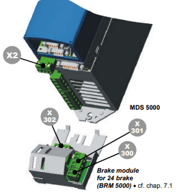
4.4 Brake Module for 24 V Brake 

The relay in the basic device for brake control is equipped with hardgold contacts. This relay is designed for control of an 

electro-magnetic brake. The brake module for 24 V brake is required for control of a 24 V brake (BRM 5000). A thermally 

monitored and short-circuit-proof, electronic semi-conductor switch is available for switching the brake. When Brake module for 

24 V brake is placed between relay and brake, the integrated filter suppresses the switch-off reactions. This also increases the 

lifespan of the relay contacts. 

For a 230 VAC brake we also recommend control via 

a coupling relay and not directly via the existing relay. 

Installation 

• Connect terminal X302 with terminal X2 

(for connection cable, see chap. 4.7.2). 

• Connect the external 24 V to the power supply of the 

brake on X300 an (for pin allocation, see chap. 5.3). 

• The brake and thermal contact lines installed in the motor 

cable are connected to X301 (for pin allocation, see chap. 5.3). 

POSIDRIVE® MDS 5000 – Mounting Instructions STÖBER ANTRIEBSTECHNIK 

4. Electrical Installation 

17

4.5 DC Link Coupling 

If you are using axes in a plant which operate in a network of generators and motors, the DC link coupling (DC coupling) can be

advantageous. When the DC-coupling is used, the excess energy of other axes is made available as drive power instead of 

converting this excess power into heat with a brake resistor. Remember that you will need a brake resistor which can absorb the

power peaks when all drives in the DC-link network brake at the same time. 

DANGER 

Danger of damage to devices! When single-phase and three-phase devices are coupled, 

the single-phase devices will be destroyed. Use only three-phase devices for the DC link 

coupling!

CAUTION 

Danger of damage to devices! When one device within the DC-link coupling network fails, 

the complete DC-link coupling network must be disconnected from the power network since 

other devices in the DC-link coupling network may be damaged. Be sure to adhere to the 

wiring of the ready-for-operation relay shown in chapter 4.5.1 (X1.1 and X1.2). When a 

failure occurs, replace all devices of one group. 
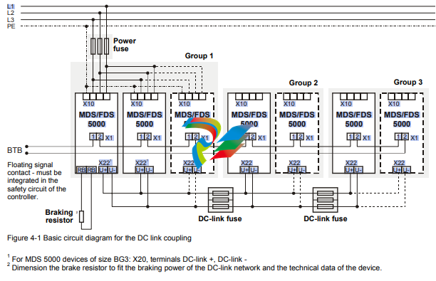
NOTE 

Please note that the parameter A38 DC power-input must be set before the DC link 

coupling will function correctly. 

Group 1: A38 = 0: inactive

Group 2 and 3: A38 = 1: active

For more details, also see the description of the parameter. 

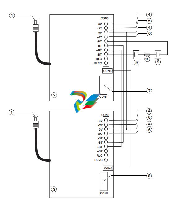
4.5.1 Basic Circuit Diagram 

The following diagram shows the basic circuiting of the DC-link coupling. The inverters can be coupled together in up to three 

groups. The table in chapter 4.5.2 shows the possible combinations. The combination determines the types of power fuse and 

DC-link fuse. 

MDS/FDS

5000

MDS/FDS

5000

MDS/FDS

5000

MDS/FDS

5000

MDS/FDS

5000

MDS/FDS

5000

MDS/FDS

5000

X10 X10 X10 X10 X10 X10 X10

X1 X1 X1 X1 X1 X1 X1

X221

X221

X22 X22 X22 1

X22 X22

RB RB U+ U+ U+ U+ U- U- U- U- U+ U+ U+ U- U- U11 1 1 22 2 2 111 222

L1

NOTE 

The certified version of the safety function is available for designs BG 0 to BG 2 as per EN 

954-1 category 3. You will find the certificate under www.stoeber.de 

The ASP 5001 may only be installed and repaired by STÖBER ANTRIEBSTECHNIK. This 

is why you should include installation in the inverter with your order of the ASP 5001. 

NOTE 

When certified use is required, the inverter must be installed in a switching cabinet with a 

protection rating of IP54. 

4.6.1 Description 

On the MDS 5000 inverter the safety function “safe torque off” can be implemented with option ASP 5001. When the safety 

function is used the inverter must be able to be switched off in two different ways. The first way to switch off the inverter uses 

the enable function. Diagnosis is performed via a binary output of the options SEA 5000, REA 5000, XEA 5001 or a fieldbus 

system. 

The second way to switch off the inverter uses the ASP 5001 option in addition. When the ASP 5001 option is activated, control 

of the end stage is switched off with the positively-driven switch elements of a safety relay. The reference value input is 

disabled, and the signal contact is switched to an external safety circuit (break contact). The motor cannot start up even when

there are defects in the end stage or the control circuit since the necessary phase sequence is no longer generated. 

Advantages of the ASP 5001 option:

• No switching of the network voltage necessary and the DC link remains charged. This permits a faster restart. 

• Less contact wear since only low voltage is switched. 

• Less additional wiring work. 

4.6.2 Use 

WARNING 

The starting lockout option only switches off the end stage. Dangerous voltages may still be 

present on the motor terminals! 

This means that the starting lockout option does not provide galvanic isolation from the 

power network. The function does not provide protection against “electrical shock.” 

During maintenance or repair work an appropriate voltage-free circuit and system protection 

are required. 

The regulations for emergency off situations must be adhered to. 

WARNING 

Since the safety function ensures that the motor torque is switched off, axes that are moving 

vertically must be protected against crashing down. 

WARNING 

Since the motor may run down in an undefined state when the starting lockout is activated 

during operation, it is essential to adhere to the switchoff sequences which will be described 

in the following section (1st and 2nd ways to switch off). 

thinklogicalVelocit Powered by ykvm MRTS Technology

The Logical Solution – KVM Extension

Velocitykvm System – 34, Transmitter and Receiver, Multi-Mode Fiber

KVM Extension System -34

Four Single-Link DVI Displays

Extension Options Include:

 USB 1.1

 USB 1.1 with Ethernet Network Extension

 USB 1.1 and USB 2.0

 USB 1.0 HID (ONLY)

Fiber Options Include:

 Single Mode

 Multi-Mode

The Velocitykvm System – 34 series is comprised of four different models, all of which are designed to support four 

Single-Link DVI displays, PS2, full duplex stereo audio, and serial (RS-232). Depending on your requirements model options 

feature either USB 1.0 HID (only), USB 1.1, USB 1.1 with Ethernet 10/100 Base-T network extension, or USB 1.1 and USB 2.0 (up 

to 480 Mbps) device ports. Using multi-mode or single-mode fiber, the system allows users to locate a DVI monitor and 

peripherals via fiber from just a few meters up to 10 kilometers away from the controlling computer securely without the loss 

of resolution. 

Powered by Thinklogical’s cutting edge, patent-pending MRTS (Multi Rate Transmission System) technology, this extension 

system transports every frame of a DVI video stream seamlessly, with no compression, or dropped frames. In addition, all high 

speed peripherals function with no latency making it ideally suited for a wide range of applications in the broadcast and 

post-production field, as well as command and control centers, universities, large scale digital signage, and any other 

commercial KVM applications. 

The System

The Velocitykvm System – 34 has a simple transmitter/receiver design which allows for ease of installation and straight 

forward deployment. Depending on the user’s infrastructure, the transmitter and the receiver can be connected by 

multi-mode or single-mode fiber optic cable. The transmitter unit connects to the CPU with the supplied peripheral 

cables. In addition, local keyboard and mouse ports are on the transmitter (local video when used with Thinklogical’s 

DVI Splitter). The receiver unit provides connections to the user interface devices.

Leveraging standard SFP+ transceivers, the system allows for the usage of either multi-mode or single-mode fiber optic 

cable. The Velocitykvm Extender – 34 requires five fibers for a multi-mode configuration. Four fibers are dedicated to the 

video and USB while the fifth fiber is the back channel for the USB and DDC. The DDC (Display Data Channel) or EDID 

(Extended Display Identification Data) information is provided to the CPU by either a generic table stored inside the 

transmitter, or from a display connected to the transmitters local port. Also, the added capability of active DDC allows the 

remote monitor to send its display capabilities to the CPU. Multi-mode and single-mode models are available with SC, ST, 

or LC type fiber connectors. Standard fiber count is five, however models with fewer fibers are available. 

The VelocityKVM System – 34 extension system offers best-in-class fiber optic performance with advanced peripheral and 

interface capability. The entire line of VelocityKVM products offer the following four model options:

Typical application extending DVI video and peripheral devices using the Velocitykvm System – 34

KVM EXTENSION – Velocity Series

Fiber

Velocitykvm System – 34 Transmitter

Fiber Connection

Velocitykvm System – 34 Receiver

Remote KVM

Microphone

Local KVM

USB 2.0 Drive

Speakers

up to 10 km

DVI Splitter Single-Link DVI

USB 1.1, PS2, Serial (RS-232), and Analog Stereo Audio (bi-directional)

For general purpose use, supports any full speed USB (1.1) peripheral, including thumb drives and tablets.

USB 1.1 with Ethernet 10/100 Base-T Network Extension, PS2, Serial (RS-232), and Analog Stereo Audio (bi-directional)

Extend Ethernet network (10/100 Base-T) through the VelocityKVM Transmitters via single mode or multi-mode fiber 

optics to the VelocityKVM Receivers. This expanded network connectivity will provide for greater peripheral capability 

with no increase in fiber or port counts.

USB 1.1, USB 2.0, PS2, Serial (RS-232), and Analog Stereo Audio (bi-directional)

Full support for USB high speed (2.0) devices (along with USB 1.1 support), ideal use for DVD drives, CDROM, Memory 

Stick, and other high speed storage and desktop peripherals. Supports full 480Mb/second transfer rates. 

USB 1.0 (HID ONLY), PS2, Serial (RS-232), and Analog Stereo Audio (bi-directional)

Designed for security conscious customers. No physical support for USB thumb drives or other full speed devices. 

Supports human interface devices only, such as keyboard, mouse, and tablets.

Key Features

Supports all Single-Link DVI video resolutions and 

one DVI display

MRTS technology 6.25Gbps allows for full frame rate 

transmission of uncompressed DVI

Requires one or two fiber optic cables 

depending on application

Flawless image quality with no frame dropping

Single mode or multi-mode fiber options extend 

signals up to: 

– 750 meters using SX+ multi-mode fiber

– 1000 meters using eSX+ multi-mode fiber 

– 10 kilometers using single-mode fiber 

Local KVM connection on the transmitter

Additional video output on the receiver

Models support USB HID, USB 1.1 and USB 2.0 compliant – 

High Speed 480 Mbps., 4-port hub

Model available with USB 1.1 and Ethernet 10/100 Base-T

network extension

Full keyboard and mouse emulation through the 

transmitter, full duplex stereo audio, serial RS-232

DDC2B/EDID compliant

Simple plug and play

Fully compatible with Thinklogical’s KVM VXRouter line

of products 

Velocitykvm System – 34 Ordering Information

VELOCITY 34: SINGLE MODE

Part Number and Description

VELOCITY 34 with USB 1.0 HUMAN INTERFACE DEVICE (only)

VEL-H00S34-LCRX Velocity KVM Extender Receiver, Four DVI, HID, KMASS, Single-Mode, LC 

VEL-H00S34-LCTX Velocity KVM Extender Transmitter, Four DVI, HID, KMASS, Single-Mode, LC 

VEL-H00S34-SCRX Velocity KVM Extender Receiver, Four DVI, HID, KMASS, Single-Mode, SC 

VEL-H00S34-SCTX Velocity KVM Extender Transmitter, Four DVI, HID, KMASS, Single-Mode, SC 

VEL-H00S34-STRX Velocity KVM Extender Receiver, Four DVI, HID, KMASS, Single-Mode, ST 

VEL-H00S34-STTX Velocity KVM Extender Transmitter, Four DVI, HID, KMASS, Single-Mode, ST 

VELOCITY 34 with USB 1.1 

VEL-000S34-LCRX Velocity KVM Extender Receiver, Four DVI, USB 1.1, KMASS, Single-Mode, LC 

VEL-000S34-LCTX Velocity KVM Extender Transmitter, Four DVI, USB 1.1, KMASS, Single-Mode, LC 

VEL-000S34-SCRX Velocity KVM Extender Receiver, Four DVI, USB 1.1, KMASS, Single-Mode, SC

VEL-000S34-SCTX Velocity KVM Extender Transmitter, Four DVI, USB 1.1, KMASS, Single-Mode, SC 

VEL-000S34-STRX Velocity KVM Extender Receiver, Four DVI, USB 1.1, KMASS, Single-Mode, ST 

VEL-000S34-STTX Velocity KVM Extender Transmitter, Four DVI, USB 1.1, KMASS, Single-Mode, ST 

VELOCITY 34 with USB 1.1 and Ethernet 10/100 Base-T Network Extension

VEL-N00S34-LCRX Velocity KVM Extender Receiver, Four DVI, USB 1.1, Network, KMASS, Single-Mode, LC 

VEL-N00S34-LCTX Velocity KVM Extender Transmitter, Four DVI, USB 1.1, Network, KMASS, Single-Mode, LC 

VEL-N00S34-SCRX Velocity KVM Extender Receiver, Four DVI, USB 1.1, Network, KMASS, Single-Mode, SC 

VEL-N00S34-SCTX Velocity KVM Extender Transmitter, Four DVI, USB 1.1, Network, KMASS, Single-Mode, SC 

VEL-N00S34-STRX Velocity KVM Extender Receiver, Four DVI, USB 1.1, Network, KMASS, Single-Mode, ST 

VEL-N00S34-STTX Velocity KVM Extender Transmitter, Four DVI, USB 1.1, Network, KMASS, Single-Mode, ST 

VELOCITY 34 with USB 1.1 and USB 2.0

VEL-U00S34-LCRX Velocity KVM Extender Receiver, Four DVI, USB 1.1, USB 2.0, KMASS, Single-Mode, LC 

VEL-U00S34-LCTX Velocity KVM Extender Transmitter, Four DVI, USB 1.1, USB 2.0, KMASS, Single-Mode, LC

VEL-U00S34-SCRX Velocity KVM Extender Receiver, Four DVI, USB 1.1, USB 2.0, KMASS, Single-Mode, SC 

VEL-U00S34-SCTX Velocity KVM Extender Transmitter, Four DVI, USB 1.1, USB 2.0, KMASS, Single-Mode, SC 

VEL-U00S34-STRX Velocity KVM Extender Receiver, Four DVI, USB 1.1, USB 2.0, KMASS, Single-Mode, ST 

VEL-U00S34-STTX Velocity KVM Extender Transmitter, Four DVI, USB 1.1, USB 2.0, KMASS, Single-Mode, ST 

VELOCITY EXTENDER OPTICS OPTION for SINGLE MODE

VOP-S36 Velocity 34 Optics Option for Transmitter or Receiver, Single Mode, 5 Fibers, 10KM, LC/UPC

VOP-S14 Velocity 34 Optics Option for Transmitter or Receiver, Single Mode, 5 Fibers, 10KM, SC/UPC or ST/UPC

Velocitykvm System – 34 Ordering Information (continued)

 100 Washington Street Contact a Thinklogical Sales Representative at 

 Milford, CT 06460 USA sales@thinklogical.com or (203) 647-8700

tm

VELOCITY 34: MULTI-MODE

Part Number and Description

VELOCITY 34 with USB 1.0 HUMAN INTERFACE DEVICE (only)

VEL-H00M34-LCRX Velocity KVM Extender Receiver, Four DVI, HID, KMASS, Multi-Mode, LC 

VEL-H00M34-LCTX Velocity KVM Extender Transmitter, Four DVI, HID, KMASS, Multi-Mode, LC 

VEL-H00M34-SCRX Velocity KVM Extender Receiver, Four DVI, HID, KMASS, Multi-Mode, SC 

VEL-H00M34-SCTX Velocity KVM Extender Transmitter, Four DVI, HID, KMASS, Multi-Mode, SC 

VEL-H00M34-STRX Velocity KVM Extender Receiver, Four DVI, HID, KMASS, Multi-Mode, ST 

VEL-H00M34-STTX Velocity KVM Extender Transmitter, Four DVI, HID, KMASS, Multi-Mode, ST 

VELOCITY 34 with USB 1.1 

VEL-000M34-LCRX Velocity KVM Extender Receiver, Four DVI, USB 1.1, KMASS, Multi-Mode, LC 

VEL-000M34-LCTX Velocity KVM Extender Transmitter, Four DVI, USB 1.1, KMASS, Multi-Mode, LC 

VEL-000M34-SCRX Velocity KVM Extender Receiver, Four DVI, USB 1.1, KMASS, Multi-Mode, SC

VEL-000M34-SCTX Velocity KVM Extender Transmitter, Four DVI, USB 1.1, KMASS, Multi-Mode, SC 

VEL-000M34-STRX Velocity KVM Extender Receiver, Four DVI, USB 1.1, KMASS, Multi-Mode, ST 

VEL-000M34-STTX Velocity KVM Extender Transmitter, Four DVI, USB 1.1, KMASS, Multi-Mode, ST 

VELOCITY 34 with USB 1.1 and Ethernet 10/100 Base-T Network Extension

VEL-N00M34-LCRX Velocity KVM Extender Receiver, Four DVI, USB 1.1, Network, KMASS, Multi-Mode, LC 

VEL-N00M34-LCTX Velocity KVM Extender Transmitter, Four DVI, USB 1.1, Network, KMASS, Multi-Mode, LC 

VEL-N00M34-SCRX Velocity KVM Extender Receiver, Four DVI, USB 1.1, Network, KMASS, Multi-Mode, SC 

VEL-N00M34-SCTX Velocity KVM Extender Transmitter, Four DVI, USB 1.1, Network, KMASS, Multi-Mode, SC 

VEL-N00M34-STRX Velocity KVM Extender Receiver, Four DVI, USB 1.1, Network, KMASS, Multi-Mode, ST 

VEL-N00M34-STTX Velocity KVM Extender Transmitter, Four DVI, USB 1.1, Network, KMASS, Multi-Mode, ST 

VELOCITY 34 with USB 1.1 and USB 2.0

VEL-U00M34-LCRX Velocity KVM Extender Receiver, Four DVI, USB 1.1, USB 2.0, KMASS, Multi-Mode, LC 

VEL-U00M34-LCTX Velocity KVM Extender Transmitter, Four DVI, USB 1.1, USB 2.0, KMASS, Multi-Mode, LC

VEL-U00M34-SCRX Velocity KVM Extender Receiver, Four DVI, USB 1.1, USB 2.0, KMASS, Multi-Mode, SC 

VEL-U00M34-SCTX Velocity KVM Extender Transmitter, Four DVI, USB 1.1, USB 2.0, KMASS, Multi-Mode, SC 

VEL-U00M34-STRX Velocity KVM Extender Receiver, Four DVI, USB 1.1, USB 2.0, KMASS, Multi-Mode, ST 

VEL-U00M34-STTX Velocity KVM Extender Transmitter, Four DVI, USB 1.1, USB 2.0, KMASS, Multi-Mode, ST 

 VELOCITY EXTENDER OPTICS OPTION for MULTI-MODE

 VOP-M12 Velocitykvm Optics Option for Transmitter or Receiver, Multi-Mode, 5 Fibers, LC

 VOP-M11 Velocitykvm Optics Option for Transmitter or Receiver, Multi-Mode, 5 Fibers, SC or ST

tycoPSU830 POWER SUPPLY AND BATTERY CHARGER

INTRODUCTION 

The PSU830 power supply is intended for use in MX/ZX/

ZXF/T2000/MX2 fire panels. It is a functional replacement for the PSB800, PSM800, PSB820 and PSB821. 

The PSU830 provides the following features: 

„ Power factor correction (PFC) to minimise loading 

effects on the AC supply and allows operation from 120 

– 240V ac. 

„ Temperature compensated, battery charger for sealed 

lead acid batteries: 

„ Battery disconnection (load shed) when operating from 

battery supply to provide deep discharge protection to 

battery set 

„ Fault monitoring includes:- 

– battery disconnected, battery wiring short, battery 

high resistance, battery voltage low, battery reverse, 

temperature compensation fault, ac supply low, 

internal charger fault 

„ Common fault output – volt free relay contacts 

„ Diagnostic LEDs for 

– AC ok 

– Battery fault 

– Charger fault 

– Ground (earth) fault 

„ Two 27VDC fused field supply outputs with short circuit 

protection, one output may be reset (turned off) under 

command from fire panel 

„ 40VDC 2.2.A output for supplying up to 4 fully loaded 

MX Digital loops, typically a single PSU830 may 

replace two PSB800 40V 1.2A supplies 

„ 5VDC output for use within fire panel/repeater 

„ Selectable Ground (earth) fault monitoring 

„ Battery charging function of two PSU830 may be connected in parallel 

TECHNICAL SPECIFICATION 

The PSU830 complies with the requirements of: 

„ EN 54-4/1997:A2-2006 Fire Detection and fire alarm 

systems; part 4, Power supply equipment 

SYSTEM COMPATIBILITY: 

„ Use only with MX/MX2/ZX/ ZXF/T2000 Fire Alarm 

Controllers 

ENVIRONMENT 

„ Indoor Application only, Land and Marine 

„ Operating Temperature: -10o

 to +55oC 

„ Storage Temperature: -20o to +70oC 

„ Operating Humidity: Up to 95% non-condensing 

DIMENSIONS (HWD): 

„ 62 x 132 x 242mm 

EMC 

„ The PSU830 complies with the following: 

„ Product family standard EN50130-4 in respect of Conducted Disturbances, Radiated Immunity, Electrostatic 

Discharge, Fast Transients and Slow High Energy 

„ EN 61000-6-3 for Emissions 

ELECTRICAL CHARACTERISTICS 

„ Input Voltage: 120-240Vac 50/60Hz (autoranging) 

„ Input Current Rated Load: 0.8-2.2ARMS

„ Rated input power: 200W maximum 

Fig. 1: PSU830 power supply and battery charger

NOTICE

Sealed lead acid batteries cannot be reliably 

charged when ambient air temperature 

around them (the battery ambient) exceeds 

50° C. 

„ Outputs 

– Non-reset: 

27V dc @ 2A

5V dc @ 2.2A Rated, 3.0A max

40V dc @ 2.2 Rated, 2.3A max

– Reset: 27V dc @ 2A

„ +27V: 21-28.8Vdc (typically 27.3V with battery fully 

charged) 

„ +40V: 39.5-40.3Vdc 

„ +5V: 4.8-5.25Vdc 

„ Rated Output 

„ Rated output of 5A to supply the panel, fire system 

loads and charge 24V battery. De-rate to 4.5A when 

used at 120VAC and ambient above 40ºC, e.g. some 

T2000 Marine applications. 

„ Maximum Alarm current 5A for 30 minutes 

„ Maximum continuous load current (excluding charging) 2.5A 

„ Rated output power: 136W 

The PSU830 cannot support all outputs fully loaded, the 

following output load combinations are possible in MX 

panel application: 

BATTERY CHARGER

A PSU830 may be used to charge 17Ah or 38Ah battery 

sets. To meet the requirements of charge to 80% rated 

capacity within 24 hours with a 38Ah battery set it is recommended that 2A or greater be allocated for battery 

charging. Points to note:

„ Trickle charge determined by battery capacity, typically 

100mA at 27.3Vdc. 

„ Maximum charging voltage 28.8V, battery at -5ºC. 

„ Minimum charging voltage 21V, condition battery discharged. 

„ Deep discharge protection, battery disconnection voltage < 20V. 

The PSU830 is not recommended for use with batteries 

that have been deep discharged. 

Recommended temperature for charging battery -5 to+ 

40ºC measured in the battery housing with thermistor lead 

assembly within 2cms from battery. Sealed lead acid batteries cannot be reliably charged when ambient air temperature around them (the battery ambient) exceeds 50ºC. 

Two PSU830 may be connected in parallel (dual PSU configuration) to provide charger output of up to 10A. All other 

outputs remain separate, i.e. 2 x 5V, 4 x 27V, 2 x 40V and 

must not be connected together. To meet the requirements 

of charge to 80% rated capacity within 24 hours with a 

65Ah battery set it is recommended that 3.4A or greater 

be allocated for battery charging. 

BATTERY REQUIREMENTS 

17Ah or 38Ah single PSU830. 

38Ah dual PSU830. Do not charge 17Ah batteries with 

dual PSU830s.

„ Standby Current Consumption: 90mA @ 24V dc 

FAULT MONITORING AND RESPONSE 

FAULT CONDITIONS THRESHOLDS

„ Low AC, < 100VAC. 

„ Battery low <22VDC

„ Battery disconnect < 20VDC

„ Battery High Resistance: 

– Single PSU: 0.6Ω

– Dual PSU: 0.3Ω

This is the maximum resistance of the battery circuit including battery, wiring and connections to the charger. 

„ Earth (ground fault), operates on the 0V, 5V, 27V and 

40V rails. Sensitivity varies with rail with respect to 

earth 

– 40V and Loop SIG < 300kohm 

– 27V < 100 kohm 

– 0V and Loop RTN < 22kohm 

DESIGN PLANNING 

Cables are to be selected in accordance with Publication 

17A-02-D and the requirements of local regulations/ code 

of practise. 

All the terminals at CON3 will accept cable up to 2.5mm2. 

To comply with EN54.2 and EN54.4 it is recommend that 

the batteries are installed in housing adjacent to the 

PSU830 and not further than 2 metres from it. All cabling 

between the PSU830 and the batteries housings must be 

protected, preferably with metal conduit, in order to provide 

adequate mechanical and EMI immunity. 

Battery resistance fault monitoring includes the connecting 

leads, < 0.1ohm, cabling must be used. The battery temperature thermistor lead assembly may be extended if 

required, thermistors must not be swapped between units. 

The PSU housing must be positioned so that convection 

cooling is unrestricted. For installations where this is not 

possible, e.g. installing T2000 fire panel into a console 

would require fan cooling of the console and/or large apertures in the T2000 housing to assist cooling of the fire 

panel within the console. 

If DC units 8800 is exceeded then a second PSU830 is 

required this provides power to the second and third 

XLM800 and is connected the same way as a PSB800 

supplied with PSB800K.

USING PSU830 WITH MX 

DESIGNER

Fire panels using modules FIM802 and XLM800 the MX 

Digital addressable loop load is defined in MX Designer, 

summary below: 

In early versions of MX Designer only PSB800 is available. 

When PSB800 is selected it is possible to determine 

PSU830 power supply loading as each loop may be loaded 

above the DC units Red warning value, provided that the 

value does not exceed 2200 DC units per loop and 8800 

DC units per PSU830. The voltage drop and AC units Red 

warning values stay the same and cannot be ignored. This 

means that in many situations a single PSU830 can be 

used where previously a combination of PSB800 and 

PSB800K were required.

DUAL PSU 

In dual PSU configuration only the charger outputs of the 

PSU830 are in parallel, all other outputs remain separate, 

i.e. 2 x 5V, 4 x 27V, 2X 40V and must not be connected 

together. For optimum operational life the panel loading 

should be divided equally between the PSU830s wherever 

possible (although not essential). MX Designer may be 

used to assist in loading of the PSU830. 

For dual PSU configuration 0V connection between units 

must be made in addition to BT+ and BT-. Cable assembly 

must be fitted between CON6 on each unit to provide fault 

monitoring. It is necessary to use PTM800 to provide wiring interconnect terminal block from the auxiliary PSU830 

to loads such as XLM800. 

17Ah battery set must not be connected in dual PSU configuration due to possibility of overcharging. 

PRODUCTS REQUIRED FOR 

INSTALLATION OF SECOND 

PSU830 

All items required for installation of second PSU830 are 

available using FG number 557.202.044 PSU830K. 

PSU830K consists of the following items:

„ 557.202.210 PSU830 Power Supply 

„ 557.201.232 PTM800 Power Terminal Module 

„ 557.201.231 PSU830 Dual Power Supply Kit

INSTALLATION, GENERAL POINTS

„ For MX2, ZX4, ZX4BB panels the second (auxiliary) 

PSU830 is installed on top of the first (primary) 

PSU830. 

„ For MX4000 and MX4000BB, panels the auxiliary 

PSU830 is installed in the battery housing. The distance between the housings is constrained by the length 

of the interconnecting cables. The recommended 

installation is battery housing beneath fire panel.

„ Connection of primary and auxiliary AC power leads is 

via a distribution block supplied with kit 557.201.231. 

The external AC supply is connected to a socket which is 

mated with distribution block. 

„ If FB800 fuseboard is required it may be mounted on 

small chassis plate above the batteries or on top of auxiliary PSU830, if the latter then PTM800 must be 

mounted on the side of the PSU830. 

„ The PTM800 should be mounted on the top of the 

PSU830 for MX4000 and MX4000BB panels. For 

ZX4 and ZX4BB it can either be mounted on top or on 

the left hand side with restricted access. For MX2 it 

would be sited on the left hand side.

„ For the ZX4 and ZX4BB panels, nylon cable ties are 

required to attach the distribution block to the metal 

bracket inside the panel housing. 

„ Monitoring of the auxiliary PSU830 is provided by ribbon cable connected between both power supplies.

„ Battery capacity must not be less than 38Ah when dual 

PSU830 is used as there is possibility of overcharging 

with smaller capacity batteries.

CONFIGURATION 

HEADERS AND LINKS 

The PSU830 has three headers to which are fitted jumper 

links, these headers enable selection of the following: 

„ Earth (ground) fault monitoring, there can only be one 

Earth fault monitoring circuit active at the fire panel. 

„ Output CON3.2 +27V may be reset (turned off) under 

CIE control. 

„ Unit may be configured for single unit or dual unit operation, link selects between primary (master) and auxiliary (slave). There can only be one primary and one auxiliary connected together, no other combinations are 

permitted. PSU830 cannot be mixed with any other 

PSU. 

Refer to Table 3, 4 and Figs. 2, 3, 4 for details of terminal 

block CON3, header and wiring configurations.

Fig. 2: PSU830 connectors, terminals and links

1 – Battery fuse

2 – Link 3

3 – 27V output fuses

4 – Diagnostic LEDs

5 – Link 4

6 – Battery temperature compensation cable and thermistor

7 – CON6 to CON6 of other PSU830 (dual PSU830 application)

8 – CON1 to FIM 802 PL2 or PTM800 if second PSU830

9 – Link 2

10 –LINK SETTINGS PRIMARY PSU830

LINK 2 (LK2, RESET_ – DIS (disable)

LINK 3 (LK3, E-FLT) – EN (enable)

LINK 4 (LK4) – MTR (master)

11 –LINK SETTINGS AUXILIARY PSU830

LINK 2 (LK2, RESET) – DIS (disable)

LINK 3 (LK3, E-FLT) – DIS (disable)

LINK 4 (LK4) – SLV (slave)

TYPICAL WIRING ARRANGEMENTS OF PSU830 

Fig. 3: PSU830 typical wiring of primary power supply

1 – AC power input

2 – Primary PSU830

3 – DC common

4 – +27.3V DC (reset)

5 – +27.3V DC (standard)

6 – 38Ah 12 volt DC batteries

7 – Fuse-lead

8 – To FIM802

Fig. 4: Wiring for primary and auxiliary PSU830

1 – AC power input

2 – Auxiliary PSU830

3 – Primary PSU830

4 – DC common

5 – +27.3V DC (reset)

6 – +27.3V DC (standard)

7 – To PTM800

8 – To FIM802

9 – 38Ah 12 volt DC batteries

10 –Fuse-lead

OPTIONS 

FB800

The fuseboard FB800 provides 8 fused outputs, it is connected to one of the 27V outputs of the PSU830. On the 

cover of the PSU830 there are four M3 tapped holes to 

accept the male/female threaded pillars supplied with the 

FB800. 

PTM800 

The PTM800 provides screw terminals for 40V, 27V and 

5V supplies, necessary when second PSU830 is used to 

supply loop power to XLM800s. The 5V, 27V and 40V outputs are not fuse protected. The PTM800 is connected to 

the PSU830 via 12 way cable assembly. It is mounted by 

four plastic pillars and two 5/8 inch 4/40 UNC screws supplied with the PTM800. The PTM800 may be mounted 

on top or on the left hand side of the PSU830.

SERVICE REPLACEMENT

PSU830 is a NOT a form fit replacement for PSB800, 

PSM800 or PSB820, refer to publication 120.415.990 

for service replacement instructions. 

PSU830 should not be used with 10Ah battery sets due to 

possibility of overcharging. 

ORDERING INFORMATION

„ PSU830 Power Supply and Battery Charger: 

557.202.210 

„ PTM800 Power Terminal Module: 557.201.232 

„ PSU830K Power Expansion Kit: 557.202.044 

RELATED DOCUMENTATION

120.415.990 PSU830 Power supply and battery charger 

installation and service replacement instructions. 

120.415.984 Installation guide – PSU830 Dual Power 

Supply kit. 

CON1 CONNECTION

„ Mini blade fuses Farnell RS

2A: 994-3811 219-3536

7.5A: 994-3854 220-0892

UNIOPUniOP CP01R-04 UniOP CP01R-04 Compact HMI devices with 5 function keys, numerical keypad and 20 characters display.

Compact HMI devices with 5 function keys, numerical keypad and 20 characters display. 

Highlights 

• Shows up to 2 or 4 rows, 20 characters 

of information

• Choice of Vacuum Fluorescent or 

Monochrome LCD

• 5 user programmable function keys 

with slide-in legends

• 5 user programmable LED indicators

• Multilanguage project capability 

• Connection to industrial bus systems 

and Ethernet with optional modules 

• IP65 front panel protection

• Version with extended operating 

temperature available

The CP HMI panels is compact low cost products yet extremely rich in functionality. The product 

support the rich common functionality of the UniOP operator panels: 

• Powerful and intuitive programming with the UniOP Designer software 

• Dual-driver communication capability (only CP01) 

• Support of more than 130 communication drivers for industrial devices 

• Optional modules for fieldbus systems (Profibus DP, DeviceNet, CANopen, Interbus) and Ethernet 

• Display data in numerical, text and bargraph format

• Recipe data storage 

• Keyboard macro editor 

• Alarms and historical alarm list 

• Eight level password protection 

Technical Data 

Display Colors Backlight Lifetime 

CP01R-04 LCD – LED 100.000 hours 

Display 

Rows/columns 4/20 

Character height 5 mm 

User definable characters 8 

Contrast regulation Software 

Memory 

User memory 512 KB 

User memory expansion 512 KB 

Front panel 

Function keys 5 

System keys 19 

Touch screen – 

User LED’s 5 

System LED’s 1 

Connections 

PC/Printer port Yes 

PLC port RS-232, RS-422, RS-485, CL 20 mA 

Aux port (fieldbus and Ethernet 

connection) 

Yes, requires optional module 

External keyboard port No 

Programming speed 9600 ÷ 38400 bps 

Functionality 

Number of variables per page Unlimited 

Dual-driver capability Yes 

Recipe memory 16 KB 

Data acquisition and trends No 

UniNet network Client/Server 

Alarms 1024 

Event list 256 

Alarm info page Yes 

Password Yes 

Battery CR2430 (3V 270mA Lithium), non rechargeable, user 

replaceable. Replace with same type or equivalent compatible 

with the operating temperature of the product 

Hardware RTC Yes 

Screen saver No 

Buzzer No 

Power supply voltage 18 ÷ 30 VDC 

Max power consumption 0.300 A at 24 VDC 

Tech-noteUniOP eTOP307

Tech-note

ptn0301-6.doc – 17.02.2014 

UniOP eTOP307 1

UniOP eTOP307 

The UniOP eTOP Series 300 combines state-of-the-art features and performance with an oustanding 

design. They are the ideal choice for HMI applications including factory and building automation. 

The eTOP307 features a bright 7” TFT widescreen (16:9) display with LED backlight and full vector 

graphic capabilities. A great high-resolution display with the appealing 16:9 look comes in the most 

compact device. Connections include Ethernet and USB

• 7” TFT color display, LED backlight

• 800×480 pixel (WVGA) resolution, 64K colors

• Advanced vector graphics

• Resistive touchscreen

• 64 MB user memory

• 10/100 Ethernet interface

• USB interface

• Connection to bus systems using optional 

plug-in modules

• Slim design. Mounting depth less than 50mm

The eTOP Series 300 HMI panels are fully compatible with UniOP Designer 6 software. 

• Powerful and intuitive programming with 

the UniOP Designer 6 software. 

• Supports more than 150 communication 

drivers. 

• Built-in Ethernet port for communication 

with devices, programming the HMI from 

Designer and retrieving data from 

computers. 

• USB host port for the connection of flash 

drives. Flash drives can be used for 

upgrading applications and firmware. 

• Optional plug-in modules for fieldbus 

systems and networks. Compatible with 

TCM and SCM modules. 

• Dual-driver communication capability. 

• Vector graphic capabilities including the 

support of multiple layers and object 

transparency. 

• Data display in numerical, text, bargraph, 

analog gauges and graphic image 

formats. Dynamic object properties 

supported. 

• Data acquisition and trend presentation. 

Trend data can be transferred to an host 

computer using the Ethernet connection. 

• Recipe data storage. Recipe data can be 

transferred to an host computer using the 

Ethernet connection or copied to flash 

drives via USB connection. 

• Multilanguage applications. Far East 

languages are supported. The number of 

runtime languages is limited only by the 

available memory. All text information in 

the application can be exported to files in 

Unicode format for easier translation. 

• Powerful macro editor to configure 

touchscreen operation 

• Alarms and historical alarm list. Alarm and 

event information can be printed or 

transferred to an host computer. 

• Eight level password protection. 

• Report printing to serial printer. Reports 

are freely configurable using Designer. 

• Ethernet-based UniNet network to share 

data between UniOP HMIs and to serve 

data using UniNet OPC Server. 

Technical Data 

Display

Type TFT 

Resolution 800×480, WVGA 

Active display area 7” diagonal 

Colors 64K 

Backlight LED 

Brightness 160 Cd/m2

typ. 

Dimming Yes 

Memory

User memory 64 MB internal Flash 

Front panel

Touchscreen Analog resistive 

User LED indicators 1 

System LED indicators 4 

Interfaces

Ethernet port 10/100 Mbit 

USB port Host interface, version 1.1 

PC/Printer port RS-232, RS-485, RS-422, 

software configurable 

PLC port RS-232, RS-485, RS-422, 

software configurable 

Aux port Yes, fieldbus and controller 

modules 

Functionality

Vector graphics Yes 

Object dynamics 

(hide/show) 

Yes 

TrueType fonts Yes 

Dual driver capability Yes 

Video input No 

Data acquisition and 

trends 

Yes 

Multilanguage Yes, number of run-time 

languages limited only by 

available memory 

Recipe memory Yes. Flash memory storage 

limited only by available 

memory 

UniNet network Client/Server 

Alarms 1024 

Event list 1024 

Password Yes 

Hardware Real Time 

Clock 

Yes, with battery back-up 

Screen saver Yes 

Buzzer Yes, audible feedback for 

touchscreen 

Ratings

Power supply voltage 24 V DC (18 to 30 Vdc) 

Current consumption 0.6A at 24Vdc(max.) 

Fuse Automatic 

Weight Approx 1.0 Kg 

Battery Rechargeable Lithium battery, 

not user-replaceable 

Environmental 

Conditions 

Operating temperature 0 to 50 °C 

Storage temperature -20 to +70 °C 

Operating and storage 

humidity 

5 – 85 % relative humidity, 

non-condensing 

Protection class IP65 (front panel) 

IP20 (rear) 

Dimensions

Faceplate LxH 187×147 mm (7.36×5.79“) 

Cutout AxB 176×136 mm (6.93×5.35“) 

Depth D+T 45+4 mm (1.77+0.16”) 

Approvals

CE Emission 

EN 61000-6-4 

Immunity 

EN 61000-6-2 

for installation in industrial 

environments 

UL UL508 Listed 

Dimensions 

Vibro-meterPiezoelectric Pressure Transducer Type CP 104

Head Office

Vibro-Meter SA, Rte de Moncor 4,

P.O. Box 1071, CH-1701 Fribourg, Switzerland

Phone : +41 26-407 11 11

Fax Industrial & Marine : +41 26-407 13 01

Fax Aerospace : +41 26-402 36 62

E-mail : vmsa@vibro-meter.ch

Internet : www.vibro-meter.com

www.meggitt.com

Sales Offices in :

♦ Germany ♦ France

♦ USA ♦ Canada

♦ Singapore ♦ United Kingdom

♦ Russia ♦ Ukraine

Agents in over 30 countries

© VIBRO-METER SA / 276-006 / 05.97 / E

Vibro-Meter is a member of the

Meggitt Aerospace Systems Division

Piezoelectric Pressure

Transducer

Type CP 104

CHARACTERISTICS

• High-temperature capability -196°C to +400°C

• Acceleration compensated

• Operational in primary circuit of ABWR

• Proven reliability

• Will meet IEEE 323-1974

FEATURES

– Internal case insulation

– VC2 type crystal element

– Frequency response:

2 Hz to 6000 Hz

– Sensitivity

190 pC/bar

WEIGHT: 150 g

DESCRIPTION

The use of VC2 type single crystal material in the CP

104 compression mode dynamic pressure transducer

provides an extremely stable instrument.

The transducer is designed for long-term monitoring

or development testing.

The CP 104 pressure transducer may be operated with

either softline or hardline cables depending on the required temperature.

Input power requirements : None

Signal transmission : 2 pole system insulated from

casing, charge output

Signal processing : Charge converter

OPERATING (at 23 °C ± 5°C)

Sensitivity (at 2 Hz) : 190 pC/bar nominal

Dynamic measuring range

(random) : 0.00005 bar to 20 bar nominal

Overload capacity (spikes) : Up to 100 bar

Linearity : ±1% over dynamic measuring range

Acceleration sensitivity : ≤0,1 pC/g (≤0.0005 bar/g)

Resonant frequency : >30 kHz

Frequency response : 2 to 6000 Hz ±5% (lower cutoff frequency is determined by

the electronics used)

Internal insulation resist. : Min. 109 Ω (107 Ω at 300°C)

Capacitance : 85 pF nominal pole/pole

30 pF nominal pole/ground

ENVIRONMENTAL

Temperature range : -196°C to +350°C

Shock acceleration : <2000 g peak (half sine, 1 ms)

along sensitive axis

Corrosion, humidity : Inconel 600, hermetically

welded

Radiations

– Gamma flux : 1011 erg/g no effect

– Neutron flux : 1018 n/cm2 no effect

Mounting : 3 Allen screws M5

Fastening torque 10 Nm

CALIBRATION : Dynamic calibration at factory

at 1 bar peak and 2 Hz (23°C).

No subsequent calibration

necessary

Accessories :

– Connectors

– Cables

– Electronics

Ordering Information :

To order please specify:

– Type and designation : CP 104 Piezoelectric Pressure Transducer

– Ordering No. : 143-104-000-1

Due to the continual development of products, Vibro-Meter reserves the right to modify these specifications without forewarning

WATLOWCLS200, MLS300, and CAS200 Communications Specification

This reference guide is designed to help applications software

programmers with the following tasks:

• Interface to Watlow Anafaze MLS300, CLS200, MLS and CLS controllers, and the CAS200 and CAS scanners via serial communications.

• Modify the communications Anafaze protocol driver in the Watlow 

Anafaze Communications Driver Kit. (If you have the communications driver kit, you don’t need to read this manual unless you want 

to modify the communications driver.)

In This Manual

The following sections are included in this guide: 

Chapter 1: Anafaze/AB Protocol. Gives an overview and explanation

of the Anafaze/Allen Bradley communications protocol.

Chapter 2: Modbus-RTU Protocol. Gives an overview and

explanation of the Modbus-RTU communications protocol

Chapters 1 and 2: Data Table Summary. Provides standard controller

data table maps for the parameters (one for each protocol).

Chapter 3: Parameters Description. Describes each parameter.

Appendix A: Communications driver.

Glossary: Explanation of commonly used terms and acronyms.

NOTE

This reference guide is not a tutorial. It does not explain

how to use the controller; it is not a programming reference; it also does not explain PID control, alarms, linear

scaling, or other topics that are explained in detail in the

controller manuals. If you need additional information

about a topic covered in this reference guide, consult the

documentation included with your controller.

Chapter 1: ANAFAZE/AB Protocol

This section explains the ANAFAZE/Allen Bradley protocol used in

Watlow Anafaze MLS, CLS, and CAS devices. These controllers

operate on serial communications links (EIA/TIA-232 or EIA-TIA-485)

at either 2400 or 9600 baud. They use 8 data bits, one or 2 stop bits, and

no parity.

Protocol Syntax

The controllers use a half-duplex (master-slave) protocol to interface to

high-level software. The host software is considered the “master” and

the controller is considered the “slave.” In other words, the software can

request information from the controller or download information to the

controller. The controller can only respond to communications

transactions initiated by the host software. The controller cannot initiate

communications.

The controller and host software communicate by sending and receiving

information in a “packet” format. A packet consists of a sequence of

bytes in a specific format; it can be as large as 256 bytes of data. (For

more information about packets, see the Packet Format section later in

this chapter.)

The numbers in the packet are sent in binary format. However, our

examples show bytes in hexadecimal format.

Control Codes

Watlow Anafaze abbreviates control codes this way

Chapter 1: ANAFAZE/AB Protocol

Transaction Sequence

Here are the four steps in a transaction between the host software and

the controller. The following example shows the transaction as an

exchange of packets. The example also assumes that there are no

communication errors in the exchange.

(1) The host software sends a packet that contains a read command or 

write command.

(2) The controller sends a DLE ACK to the host software.

(3) The host software receives a reply packet from the controller. 

(4) The host software sends a DLE ACK.

The following flowchart shows a transaction with no error handling.

NOTE

Due to the difference between the processing speeds of the

controller and PCs, it may be necessary to delay the computer’s acknowledgement (ACK) in order for the controller

to receive it. A delay of 200 ms should suffice

Packet Format

Messages are transmitted in the form of packets. Command and reply

packets specify the source and destination addresses, whether to read or

write, the block of data to read or write, etc.

A packet contains a sequence of binary bytes formatted this way:

Sending Control Codes

To send a control code, send a DLE before the control code to

distinguish it from data.

Sending a DLE as Data

When you send a byte with an x10, (a DLE), the controller and software

interpret it as a command. Therefore, to send a DLE as data, send

another DLE immediately before it (DLE DLE). 

Codes in a Packet

This section describes the sequence of bytes in a packet, in the order the

host software or controller sends them.

DLE STX

• The DLE STX byte signals the beginning of a transmission. Every 

packet of information starts with the control codes DLE STX. 

DST

• The DST byte is the address of the destination device (usually a controller; the first Watlow Anafaze controller is at x08).

NOTE

When host software communicates with an MLS, a CLS, or

a CAS in ANAFAZE or AB protocol, it does not send the

controller’s actual address. Since the protocol reserves

device addresses 0 to 7, the host software sends the value

(controller address + 7), instead of the actual device

address.

SRC

• The SRC byte is the device address of the packet’s source. The host 

software is usually designated address x00.

DLE STX DLE ETX BCC/CRC

DST SRC CMD STS TNSL TNSH ADDL ADDH DAT

CMD

• The CMD byte indicates the command that the host software sends 

to the controller. The software sends a read (x01) or write (x08). 

When the controller replies, it returns the read or write command 

with the 7th bit set—in other words, it sends an x41 or x48.

STS (The Status Byte)

• The controller uses the status byte, or STS, to return general status 

and error flags to the host software. (The controller ignores the status 

byte in the host software’s command packet.) The next table shows 

status byte values and definitions. 

• An “x” in the status bytes below indicates that the associated nibble 

may contain additional information. In most cases, the status byte is 

composed of two independent nibbles. Each nibble is independent 

so that two codes can return at once. For example, status code F1 

indicates that data has changed (Fx) and the controller is being 

updated through the front panel (x1).

Status

in Hex Description

00 The controller has nothing to report, or AB protocol is selected.

01 Access denied for editing. The controller is being updated through the 

front panel.

02 AIM Comm failure.

A0 A controller reset occurred.

Cx The controller received a command that was not a block read or block 

write. (Command Error)

Dx The block write command attempted to write beyond a particular parameter block boundary, or the host software attempted to access a data table 

block that does not exist. (Data Boundary Error)

Ex The Alarm_Status variable has changed. The software should query the 

alarm status block to determine the particular alarm flag that changed.

Fx The controller altered shared data, either internally (from the firmware) or 

externally (from the keyboard). The host software should read the Data 

Changed Register to determine which data has been altered and update 

its own run-time memory

TNSL

• Least significant byte of the transaction number. This is the first half 

of a “message stamp.”

• The controller sends back the TNSL and TNSH exactly as it received 

them, so host software can use the TNSL and TNSH bytes to keep 

track of message packets.

TNSH 

• Most significant byte of the transaction number. This is the second 

half of the “message stamp.” 

ADDL

• The low byte of the beginning data table address of the block of data 

to read or write.

ADDH

• The high byte of the beginning data table address of the block of data 

to read or write.

DATA

• The new values to be set with a write command, or the requested data 

in a response to a read command.

DLE ETX

• Every packet of information must end with the codes DLE ETX. 

These codes signal the end of a transmission.

BCC or CRC

• Communications packets include a one- or two-byte error check at 

the end of the packet. There are two error check methods: Block 

Check Character (BCC), which requires 1 byte, and Cyclic Redundancy Check (CRC), which requires 2 bytes.

Watlow Anafaze recommends that you use the default error check

method, BCC. It is easier to implement than CRC, and it is acceptable

for most applications.

Select one error check method and configure both software and

controller for that method, or they will be unable to communicate.

The error check methods work this way:

Block Check Character (BCC)

BCC checks the accuracy of each message packet transmission. It

provides a medium level of security. The BCC is the 2’s complement of

the 8-bit sum (modulo-256 arithmetic sum) of the data bytes between

the DLE STX and the DLE ETX. (1’s complement +1)

• BCC does not detect transposed bytes in a packet. 

• BCC cannot detect inserted or deleted 0 values in a packet.

• If you have sent an x10 as data (by sending DLE x10) only one of the 

DLE data bytes is included in the BCC’s sum (the DLE = x10 also).

For instance, the block read example shown in the examples section, 

adds x08 00 01 00 00 80 02 10. Note that the x10 representing DLE 

has been left out of the calculation. The sum should come to x9B.

Cyclic Redundancy Check (CRC)

CRC is a more secure error check method than BCC. It provides a very

high level of data security. It can detect:

• All single-bit and double-bit errors.

• All errors of odd numbers of bits.

• All burst errors of 16 bits or less.

• 99.997% of 17-bit error bursts.

• 99.998% of 18-bit and larger error bursts.

The CRC is calculated using the value of the data bytes and the ETX

byte. At the start of each message packet, the transmitter must clear a

16-bit CRC register. 

When a byte is transmitted, it is exclusive-ORed with the right 8 bits of

the CRC register and the result is transferred to the right 8 bits of the

CRC register. The CRC register is then shifted right 8 times by inserting

0’s on the left. 

Each time a 1 is shifted out on the right, the CRC register is ExclusiveORed with the constant value xA001. After the ETX value is

transmitted, the CRC value is sent, least significant byte (LSB) first.

Below is a structured English procedure from AB Manual:

data_byte = all application layer data, ETX

CLEAR CRC_REGISTER

FOR each data_byte

GET data_byte

XOR (data_byte, right eight bits of CRC_REGISTER)

PLACE RESULT in right eight bits of CRC_REGISTER

DO 8 times

Shift bit right, shift in 0 at left

IF bit shifted =1

XOR (CONSTANT, CRC_REGISTER)

PLACE RESULT in CRC_REGISTER

END IF

END DO

END FOR

TRANSMIT CRC_REGISTER as 2-byte CRC field

The host software sends two kinds of commands: block reads and block

writes. This section shows examples of both commands.

NOTE

If you read data from a loop set to SKIP, the controller will

send an empty packet for that loop.

This section does not show how to calculate the error check value

included with every packet. For help calculating the error check value,

see the section on BCC or CRC earlier in this chapter.

Block Read

This example shows the block read command the host software sends,

the controller’s responses, and the software’s acknowledgment. 

Situation: Read process variables for loops 1 to 8. 

• 8 process variables 2 bytes each = 16 bytes from data table address 

x0280.

• Character values are represented in hex. 

• The sender is device address 0. 

• The destination is device address 8 (controller address 1). 

• The software sends transaction number 00

Data for a Write Command

For a block write command, the block contains the bytes to write (up to

242 bytes of data). The controller sends back a message packet without

data.

Two-Byte Data Types

For two-byte data types, like process variable and setpoint, the

controller or host software sends the data in two-byte pairs with the least

significant byte first.

Figuring Block Size

In order to read parameter values, you must know how many bytes to

request. Parameter values are stored contiguously such that the setpoints

for all the loops are stored together and in loop number order. For

example, to read the deviation alarm deadband value for loops one to

five, you would read five bytes starting at x05A0. Some parameters,

such as setpoint, require two bytes of memory to store. So, for example,

if you want to read the setpoint for four loops, you must read eight

bytes.

Figure total block size in bytes for most loop parameters this way (do

not forget the pulse loop):

(Data Size) * (Number of Loops)

Some parameters have values for both heat and cool. Figure block size

for such a parameter this way:

2 * (Data Size) * (Number of Loops)

One exception is the units for each loop. Figure the data size for the

units this way:

3 * (Number of Loops)

Parameters that are not loop parameters (like system status, digital

inputs, or digital outputs) have specific data sizes. These data sizes are

listed in the data table in the next section

Anafaze/AB Data Table Summary

Each address holds one byte of data. Each parameter value requires one

or two addresses to store depending on the type of data. The table below

indicates the number of bytes for each data type. The data type for each

parameter is indicated in the tables on the following pages.

Because each loop is individually configurable, the number of instances

of many parameters depends on the number of loops in the controller.

Therefore, the number of bytes for these parameters is listed in the

tables on the following pages in terms of the number of loops in the

controller.

The storage requirements for some parameters depend on the number of

digital inputs or digital outputs in the controller (MAX_DIGIN_BYTES

and MAX_DIGOUT_BYTES). The storage of ramp-soak profile

parameters depend on the number of profiles (MAX_RSP), the number

of segments per profile (MAX_SEG), the number of triggers per

segment (MAX_TRIG) and the number of events per segment

(MAX_EVENT).

The table below shows the values for each of these factors. Use them to

calculate the number of bytes for each parameter.

Data Type and Symbol Data Size

Unsigned char (UC) 1 byte

Signed char (SC) 1 byte

Unsigned int (UI) 2 bytes

Signed int (SI) 2 bytes

Ordering of Heat and Cool Channel Parameters

For parameters that have both heat and cool settings the heat values are

stored in the first registers and the cool values are stored in the registers

starting at the listed address plus MAX_CH.

NOTE

Data table parameters 46 to 60 and 100 are ramp-soak

parameters. They are only used in controllers with the

ramp-soak option. Parameters 81 to 95 are enhanced features and only available in controllers with the enhanced

features option.

Ordering of Ramp-Soak Profile Parameters

Ramp-soak profile parameters are ordered first by profile, then by

segment where applicable. So, for example, the first eight bytes of the

Ready Events parameter are the ready segment event states for the first

profile (profile A) and the next eight bytes are for profile B and so on. In

the case of the segment triggers, the first byte contains the first trigger

setting for the first segment of profile A, the second byte contains the

settings for the second trigger for the first segment of profile A, the third

byte contains the settings for the first trigger for the second segment of

profile A and so on.

Anafaze/AB Protocol Data Table

Number Description Address 

in Hex Type Number of Bytes

0 Proportional Band/Gain 0020 UC MAX_CH * 2

1 Derivative Term 0060 UC MAX_CH * 2

2 Integral Term 00A0 UI MAX_CH * 4

3 Input Type 0120 UC MAX_CH

4 Output Type 0180 UC MAX_CH * 2

5 Setpoint 01C0 SI MAX_CH * 2

6 Process Variable 0280 SI MAX_CH * 2

7 Output Filter 0340 UC MAX_CH * 2

8 Output Value 0380 UI MAX_CH * 4

9 High Process Alarm Setpoint 0400 SI MAX_CH * 2

10 Low Process Alarm Setpoint 04C0 SI MAX_CH * 2

11 Deviation Alarm Band Value 05A0 UC MAX_CH 

12 Alarm Deadband 0600 UC MAX_CH

13 Alarm Status 0660 UI MAX_CH * 2

14 Not used 06A0 128

Search for products

Back to Top
Product has been added to your cart