1.1 Warnings, legal information and safety
1.1.1 Warnings and notes
Throughout this document, a number of warnings and notes with helpful user information will be presented. To ensure that these are
noticed, they will be highlighted as follows in order to separate them from the general text.
Warnings
DANGER!
This highlights dangerous situations. If the guidelines are not followed, these situations could result in death, serious
personal injury, and equipment damage or destruction.
CAUTION
This highlights potentially dangerous situations. If the guidelines are not followed, these situations could result in personal
injury or damaged equipment.
Notes
INFO
Notes provide general information, which will be helpful for the reader to bear in mind.
1.1.2 Legal information and disclaimer
DEIF takes no responsibility for installation or operation of the generator set or switchgear. If there is any doubt about how to install
or operate the engine/generator or switchgear controlled by the Multi-line 2 unit, the company responsible for the installation or the
operation of the equipment must be contacted.
NOTE The Multi-line 2 unit is not to be opened by unauthorised personnel. If opened anyway, the warranty will be lost.
Disclaimer
DEIF A/S reserves the right to change any of the contents of this document without prior notice.
The English version of this document always contains the most recent and up-to-date information about the product. DEIF does not
take responsibility for the accuracy of translations, and translations might not be updated at the same time as the English document.
If there is a discrepancy, the English version prevails.
1.1.3 Safety issues
Installing and operating the Multi-line 2 unit may imply work with dangerous currents and voltages. Therefore, the installation should
only be carried out by authorised personnel who understand the risks involved in working with live electrical equipment.
DANGER!
Be aware of the hazardous live currents and voltages. Do not touch any AC measurement inputs as this could lead to injury
or death.
1.1.4 Electrostatic discharge awareness
Sufficient care must be taken to protect the terminal against static discharges during the installation. Once the unit is installed and
connected, these precautions are no longer necessary.
1.1.5 Factory settings
The Multi-line 2 unit is delivered from factory with certain factory settings. These are based on average values and are not
necessarily the correct settings for matching the engine/generator set in question. Precautions must be taken to check the settings
before running the engine/generator set.
1.2 About the Operator’s Manual
1.2.1 General purpose
This Operator’s Manual mainly includes general product information, display readings, push-button and LED functions, alarm
handling descriptions and presentation of the log list.
The general purpose of this document is to give the operator important information to be used in the daily operation of the unit.
DANGER!
Please make sure to read this document before starting to work with the Multi-line 2 unit and the generator set to be
controlled. Failure to do this could result in human injury or damage to the equipment.
1.2.2 Intended users
This Operator’s Manual is mainly intended for the daily user. On the basis of this document, the operator will be able to carry out
simple procedures such as start/stop and control of the generator set.
1.2.3 Contents and overall structure
This document is divided into chapters, and in order to make the structure simple and easy to use, each chapter will begin from the
top of a new page.
2.1 General
This chapter deals with the display unit including the push-button and LED functions.
2.2 Display (DU-2) layouts
INFO
The display dimensions are H × W = 115 × 220 mm (4.528” × 9.055”).
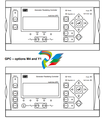
2.2.1 GPC
GPC – standard
2.3 Display push-buttons and LEDs
2.3.1 Push-button functions
The functions for all display push-buttons are described below:
INFO: Moves directly to the alarm list where all unacknowledged and present alarms are displayed.
JUMP: Enters a specific menu number selection. All settings have a specific number attached to them. The JUMP button
enables the user to select and display any setting without having to navigate through the menus.
VIEW: Shifts the first line displaying in the setup menus. Push two seconds to switch to master display in case more than
one display is connected (master password is required).
LOG: Jumps directly to the event and alarm log.
Moves the cursor left for manoeuvring in the menus.
Increases the value of the selected set point (in the setup menu). In daily use, this button function is used to switch
between displayed percentage or real value of produced power (kW), reactive power (kvar) and apparent power
(kVA) in View 3 (V3).
Selects the underscored entry in the fourth line of the display.
Decreases the value of the selected set point (in the setup menu). In daily use, this button function is used to switch
between displayed percentage or real value of produced power (kW), reactive power (kvar) and apparent power
(kVA) in View 3 (V3).
Moves the cursor right for manoeuvring in the menus.
BACK: Jumps one step backwards in the menu (to previous display or to the entry window).
REMOTE: Activates the remote mode. The push-buttons for START/STOP/GB open/GB close are deactivated. The control is
external.
LOCAL: Activates the local mode. The push-buttons for START/STOP/GB open/GB close are activated.
START: Activates the engine start sequence (only active in LOCAL mode).
STOP:
Activates the stop sequence (only active in LOCAL mode) including cooling down. When the STOP push-button is
pressed during cooling down, the cooling down time is interrupted immediately and the ext. stop timer starts
running.
2.3.2 LED functions
Each LED located on the display has its own function. The colour is green, red or yellow (fixed or flashing) dependent on its function.
The functions for all display LEDs are described below:
Alarm:
LED red flashing indicates that unacknowledged alarms are present.
LED red fixed light indicates that ALL alarms are acknowledged, but one or more alarms are still present.
LED off when no alarm is present.
Run:
LED yellow when a running feedback failure is active. (G V/Hz OK, but no running feedback).
LED green indicates that the generator is running and the voltage and frequency are OK.
LED off when no running feedback and no voltage and frequency are measured.
G V/Hz (~): LED yellow when the DG is running and V/Hz not OK.
LED green when the DG is running and the V/Hz OK timer has expired.
Open:
LED red when the breaker is tripped by a protection function.
LED yellow when the breaker is deloaded.
LED green when the breaker is open.
LED off when the breaker is closed.
Closed:
LED yellow indicates that the synchronisation function is active.
LED green when the breaker is closed.
LED off when the breaker is open.
BB V/Hz (~):
LED green when BB V/Hz OK.
LED yellow when BB V/Hz not OK.
LED red when BB voltage is zero (dead bus).
Ready:
LED green when the unit is ready for operation.
LED off when the unit is not ready (for example, the start enable is not activated or an active block, trip or
shutdown alarm is present).
This indication is to tell the user whether the controller (not the engine) is ready or not.
Regulator ON:
LED green when the regulator is activated.
LED yellow when regulator is activated but no output has been selected for governor interface.
LED off when the regulator is off.
Remote: LED green when remote mode is active.
LED off when local or SWBD mode is active.
Local: LED green when local mode is active.
LED off when remote or SWBD mode is active.
Power: LED green indicates that the auxiliary supply is switched on.
Self check: LED green indicates that the unit is OK.
2.4 Lamp test and dimmer functions
2.4.1 Lamp test
Place the cursor under SETUP and press the push-button to activate the DU-2 lamp test.
All LEDs on the DU-2 and AOP-1 will turn yellow except the power LED.
2.4.2 Dimmer function
The dimmer function of the display backlight and LEDs is accessed via the JUMP menu 9150.
The illumination intensity of the backlight and the LEDs of each display panel is adjustable by using the JUMP push-button. This
adjustment is done by means of the and push-buttons on the display, and the level of the adjustment will be saved in
the display internal memory by pressing the ENTER push-button
Procedures for setup
INFO
The complete parameter list is presented in the separate Parameter List document of the Multi-line unit in question:
GPC/GPC Gas/GPC Hydro/GPU Hydro document number 4189340580, GPU/GPU Gas/PPU document number
4189340581.
This chapter deals with the procedure to be followed when the parameters of the unit are set up from the initial point of finding the
individual parameter description to the actual setup. By use of various illustrations, the following will guide the user through the
whole procedure of parameter setup step by step.
6.2 Finding the selected parameter
The first step in the parameter setup is to find the correct parameter descriptions. All parameter descriptions in the Parameter List
document are intended for reference purposes. The descriptions are structured according to their parameter titles and the main
parameter group to which they belong.
6.3 Parameter descriptions
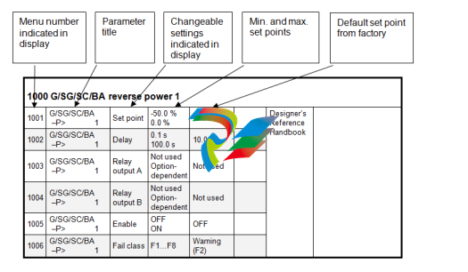
In the parameter list, each parameter description is structured according to the same principles. Under the parameter title heading,
the detailed parameter descriptions are illustrated and presented. First, a table indicating the parameter facts related to the
individual parameter title is presented:
INFO
Due to the character of the parameters there may be small differences between the individual tables.
The first column indicates the menu number in the display.
The second column indicates the name of the setting.
The third column describes the function of the parameter.
The fourth column indicates the minimum/maximum set point available for this setting
The fifth column indicates the default set point of the unit from the factory. When it is necessary, additional information will be
supplied below the table in order to make the individual parameter descriptions as informative as possible.
6.4 Setup
At this point of the process, the specific parameter description will have been located. Now, follow the menu structure presented
earlier in this manual to set up the individual parameters. (In this overall example, we have chosen to change the set point of the
parameter 1000 G -P>).
Step 1: Enter the setup menu via SETUP in the fourth display line in the entry window.
Step 2: Enter the protection menu via PROT in the fourth display line in the setup menu.
Step 3: Use the and push-buttons to locate the selected parameter.
Step 4: Enter the set point menu via SP in the fourth display line.
Step 5: Enter password to change the set point.
Step 6: Use the and push-buttons to increase/decrease the set point setting.
Step 7: Move the “underscore” to save and press SEL; the new set point setting has now been saved.
Leave a comment
Your email address will not be published. Required fields are marked *