GENERAL
This document describes the general specifications
of the FCN autonomous controller with NFCP501/
NFCP502 CPU module. (FCN is an acronym for field
control node.)
Notation in this document:
• The term “FCN” refers to the module consisting type
autonomous controllers.
• The term “FCN-500” refers to the autonomous
controllers with NFCP501/NFCP502 CPU module.
For Function, refer to FCN Autonomous Controller
Functions (FCN-500), GS 34P02Q03-01E.
FCN Autonomous Controller
Hardware (FCN-500)
Yokogawa Electric Corporation
2-9-32, Nakacho, Musashino-shi, Tokyo, 180-8750 Japan
GS 34P02Q14-01E
GS 34P02Q14-01E
©Copyright Mar. 2016(YK)
20th Edition Apr. 1, 2022(YK)
FEATURES
• High-performance, high-reliability modular controller
• Memory with ECC
• Low heat dissipation eliminates the need for a fan
• A wealth of RAS features — CPU self-diagnostics, temperature monitoring, I/O diagnostics, and more
• The CPU, power supply module, internal communication bus on backboard (SB bus), E2 bus (extension bus), and
control network (Ethernet port 1 and 2) can all be duplexed, and all modules are hot-swappable. Use a couple of the
CPU module of the same type to make the CPU module duplex configuration.
• Can function as link active schedulers (LASs) for low-speed voltage mode (H1) FOUNDATION Fieldbus segments,
and link up FOUNDATION Fieldbus-enabled field devices.
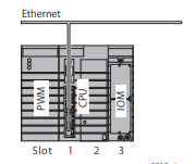
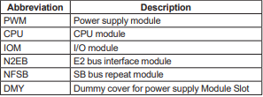
CONFIGURATION
An FCN-500 consists of the following:
• Base module
• Power supply module
• CPU module
• E2 bus interface module (extending the unit) (*1)
• SB bus repeat module (extending the SB bus to connect an extension unit) (*1)
• I/O modules
*1: SB bus repeat module and E2 bus interface module can not be used together.
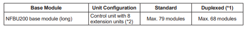
There are four types of base module.
– NFBU200 base module (long): Control unit and extension unit sharing,
duplexed power supply possibility
– N2BU051 base module (short): Control unit and extension unit sharing
– NFBU050 base module (short): Control unit only, for low power
– N2BU030 base module (compact): Control unit and extension unit sharing
l Control unit alone
The control unit is unit with CPU module. The maximum number of I/O modules that can be implemented depends on
the type of base module and the number of CPUs.
Maximum I/O Module Configurations
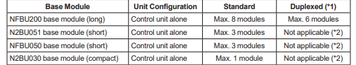
Base Module Unit Configuration Standard Duplexed (*1)
NFBU200 base module (long) Control unit alone Max. 8 modules Max. 6 modules
N2BU051 base module (short) Control unit alone Max. 3 modules Not applicable (*2)
NFBU050 base module (short) Control unit alone Max. 3 modules Not applicable (*2)
N2BU030 base module (compact) Control unit alone Max. 1 module Not applicable (*2)
*1: When CPU modules are duplexed
*2: Neither power supply nor CPU modules can be duplexed on N2BU051, NFBU050 or N2BU030
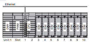
Example: Standard control unit
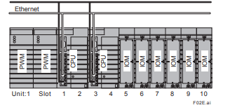
Example: Control unit with duplexed CPU and power supply modules
Example: Short control unit
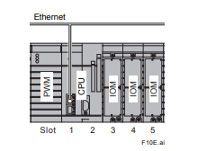
Example: Compact control unit
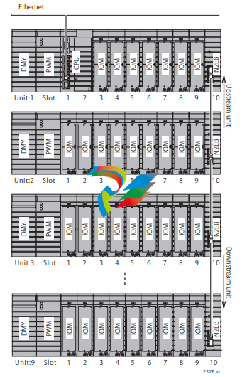
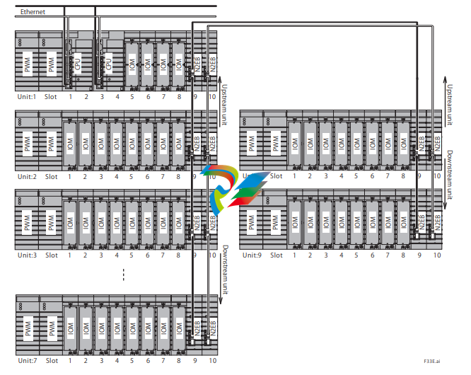
l Unit extension with E2 bus
Up to eight extension units can be connected to the control unit using the E2 bus interface modules. Two ports of
the E2 bus interface module mounted on the control unit can be connected to extension units as separate lines. The
maximum number of extendable units that can be connected is a maximum of 8 units in total of two lines. Three types
of base modules (NFBU200, N2BU051 or N2BU030) can be used as control unit and extension unit. By installing two
E2 bus interface modules in each base module, it is possible to duplex E2 bus. (*1)
Connect each E2 bus interface module with UTP straight cable (CAT 5e or higher). The distance between units can be
extended up to 100 m.
*1: When using the compact base module for the control unit, it is not possible to duplex the communication lines.
Maximum I/O Module Configurations
Note: NFCP501/NFCP502 CPU module style S2 or later is required to use the E2 bus interface module.
*1: When CPU and E2 bus interface modules are duplexed.
*2: When NFBU200 base modules are used in all extension units.
Extension of Transmission distance by Optical fiber
The transmission distance between units can be extended by converting the system from UTP straight cable to
fiber optic cable with third party’s media converters. Only Layer 1 (Physical Layer) media converters which simply
convert packets from electric signal to optical signal can be used for the E2 bus. Refer to the verified media converter
information and precaution on Yokogawa Partner Portal STARDOM site when choosing the model.
Example: Standard control unit + 8 extension units with E2 bus interface modules / 1 lines
Example: Control unit with duplexed CPU modules, power supply modules, and E2 bus + 8 extension units
/ 1 lines

Example: Control unit with duplexed CPU modules, power supply modules, and E2 bus + 8 extension units
/ 2 lines
Note: The CPU module, power supply module, and E2 bus can be made duplex individually, when required
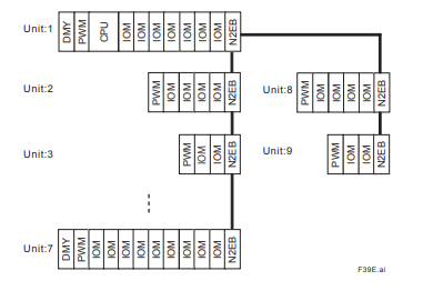
Example: Mixed base module configuration, E2 bus + 8 extension units / 2 lines
Note: Three kinds of base modules (NFBU200, N2BU051 or N2BU030) can be arranged according to the number of I/O points
and installation environment required for the control unit and extension unit.
Leave a comment
Your email address will not be published. Required fields are marked *