PMC expansion combined with a high-performance VME processor
The MVME2600 series is a family of VME processor modules based on the Motorola
PowerPlus VME architecture with PowerPC architecture-compatible microprocessors.
The flexibility of the MVME2600 provides an excellent base platform that can be
quickly and easily customized for a variety of industry-specific applications.
Designed to meet the needs of military and aerospace, industrial automation, and
medical imaging market segments, the MVME2600 applies to a variety of applications.
DRAM expansion mezzanines enable memory upgrades to the maximum 512MB of
ECC DRAM without requiring additional VME slots.
■ MPC60x class of microprocessors
■ 16KB/16KB or 32KB/32KB L1 cache
■ 256KB L2 cache
■ Up to 512MB ECC DRAM on-board memory
■ 8MB on-board Flash, 1MB socketed
■ 64-bit PCI mezzanine connector
■ On-board debug monitor with self-test diagnostics
■ IEEE P1386.1 compatible 32/64-bit PMC expansion
slot
■ Two or three async, one or two sync/async serial
ports
■ Ethernet transceiver interface with 32-bit PCI local
bus DMA
■ 8- or 16-bit Fast SCSI-2 bus interface
■ Parallel, floppy, keyboard, and mouse interfaces
■ 8KB x 8 NVRAM and time-of-day clock with
replaceable battery backup
■ Four 32-bit timers, one watchdog timer
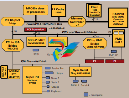
PCI Expansion
MVME2600 modules have a 64-bit PCI connection to
support PCI expansion carriers such as Motorola
PMCspan. Design details for the connector and electrical
specifications are available from your local Motorola
sales representative.
Memory Modules
The MVME2600 series has a modular memory design.
Mezzanine arrays support up to 512MB.
Transition Modules
Two artwork variants of the MVME2600 are available.
One series provides backward compatibility with the
MVME712M transition module I/O, while the other
series accepts the MVME761 transition module
featuring an additional sync/async serial port, a
10/100BaseTX Ethernet interface, Fast 16-bit SCSI, and
an IEEE 1284 compatible parallel port.
MVME761
The MVME761 transition module provides
industry-standard connector access to the IEEE 1284
parallel port, a 10BaseT or 100BaseTX Ethernet port via
an RJ-45 connector, two DB-9 connectors providing
access to the asynchronous serial ports configured as
EIA-574 DTE and two HD-26 connectors providing access
to the sync/async serial ports. These serial ports,
labeled as Serial 3 and Serial 4 on the face plate of the
MVME761, are individually user configurable as
EIA-232, EIA-530, V.35, or X.21 DCE/DTE via the
installation of Motorola serial interface modules (SIMs).
A P2 adapter provides interface module signals to the
MVME761 transition module. The 3-row P2 adapter can
be used for 8-bit SCSI. A 5-row P2 adapter supports
16-bit SCSI and PMC I/O.
MVME712M
The MVME712M transition module provides
industry-standard connector access to the Centronics
parallel port, an AUI port and four DB-25 connectors,
providing access to the asynchronous/synchronous
serial ports jumper configurable as EIA-232 DCE or DTE.
A P2 adapter provides interface signals to the
MVME712M transition module. The 3-row P2 adapter
can be used for 8-bit SCSI.
To gain access to the additional user-definable I/O pins
provided via the 5-row VME64 extension connector, a
special P2 adapter board is available. This adapter panel
replaces the traditional 3-row P2 adapter and extends its
capability by providing access to the PMC I/O pins.
Several other variations of the MVME712M are
available for combinations of I/O and connectors.
Firmware Monitor
Firmware must fulfill the traditional functions of test and
initialization, in addition to operating system boot
support. The MVME2600 firmware monitor exceeds
these requirements with a proven monitor from the
embedded VME leader. It expands features like
power-up tests with extensive diagnostics, as well as a
powerful evaluation and debug tool for simple checkout
or when high-level development debuggers require
additional support. All this is included with the
MVME2600 firmware, plus it supports booting both
operating systems and kernels.
Operating Systems and Real-Time Kernels
MVME2600 DETAILS
Motorola Computer Group: AIX
Integrated Systems, Inc.: pSOSystem
Lynx Real-Time Systems,
Inc.:
LynxOS
Microware Systems
Corporation:
OS-9/OS-9000
Microtec: VRTX32
Wind River Systems, Inc.: VxWorks
Processor
Memory
PCI Expansion Connector
VMEbus ANSI/VITA 1-1994 VME64 (IEEE STD 1014)
Ethernet Interface
SCSI Interface
Asynchronous Serial Ports
SPECIFICATIONS
Microprocessor: MPC603 MPC604 MPC604
Clock Frequency: 200 MHz 333 MHz 400 MHz
On-chip Cache (I/D): 16K/16K 16K/16K 16K/16K
Memory Type: 60 ns FPM or 50 ns EDO 60 ns FPM or 50 ns EDO 60 ns FPM or 50 ns EDO
MAIN MEMORY: Dynamic RAM
Capacity (60ns FPM): 32MB on RAM200
Capacity (50ns EDO): 128, 256, or 512MB on RAM200
Single Cycle Accesses: 9 read/4 write
Read Burst Mode (60ns
FPM):
9-1-2-1 idle; 3-1-2-1 aligned page hit
Read Burst Mode (50ns
EDO):
8-1-1-1 idle; 2-1-1-1 aligned page hit
Write Burst Mode: 4-1-1-1 idle; 3-1-1-1 aligned page hit
Architecture: 128-bit, two-way interleaved
Parity/ECC: No/Yes
L2 CACHE: 256KB
Cache Bus Clock
Frequency:
Processor clock divided by 2
FLASH: On-board programmable
Capacity: 1MB via two 32-pin PLCC/CLCC sockets;
8MB surface mount
Read Access (8MB
port):
68 clocks (32 byte burst)
Read Access (1MB
port):
260 clocks (8 byte burst)
Write Access
(1MB/8MB):
19 clocks (2 bytes/8 bytes)
NVRAM: 8KB (4KB available for users)
Cell Storage Life: 50 years at 55° C
Cell Capacity Life: 10 years at 100% duty cycle
Removable Battery: Yes
Address/Data: A32/D32/D64
PCI Bus Clock: 33 MHz
Signaling: 5 V
Connector: 114-pin connector located on the planar of
the MVME2600 between P1 and P2
Controller: Tundra Universe
DTB Master: A16–A32; D08–D64, BLT
DTB Slave: A24–A32; D08–D64, BLT, UAT
Arbiter: RR/PRI
Interrupt
Handler/Generator:
IRQ 1–7/Any one of seven IRQs
System Controller: Yes, jumperable or auto detect
Location Monitor: Two, LMA32
MVME761 MVME712M
Controller: DEC 21140 DEC 21140
Interface
Speed:
10/100Mb/s AUI (10Mb/s)
PCI Local bus
DMA:
Yes, with PCI burst Yes, with PCI burst
Connector: Routed to P2,
RJ-45 on MVME761
Routed to P2,
DB-15 AUI on
MVME712M
MVME761 MVME712M
Controller: Symbios 53C825A Symbios 53C825A
PCI Local Bus
DMA:
Yes, with PCI local bus
burst
Yes, with PCI local bus
burst
Asynchronous: 5.0MB/s 5.0MB/s
Synchronous: 10.0MB/s (8-bit mode),
20.0MB/s (16-bit mode)
10.0MB/s (8-bit mode),
20.0MB/s (16-bit mode)
Connector: Routed to P2, 50- or
68-pin on
MVME761EXT
Routed to P2, SCSI D-50
on MVME712M
MVME761 MVME712M
Controller: PC87308 PC87308,
85230/8536
Number of
Ports:
Two, 16550 compatible Two, 16550 compatible
and one 85230/8536
Configuration: EIA-574 DTE EIA-232 DCE/DTE
Async Baud
Rate, bps
max.:
38.4K EIA-232, 115Kb/s
raw
38.4K EIA-232, 115Kb/s
raw
Connector: Routed to P2, DB-9 on
MVME761
Routed to P2, DB-25 on
MVME712M
Synchronous Serial Ports
Parallel Port
Counters/Timers
Floppy
Mouse Interface
Keyboard Interface
IEEE P1386.1 PCI Mezzanine Card Slot
Board Size
Miscellaneous
Reset and abort switches on front panel; six LEDs for FAIL, CHKSTP,
CPU, PCI, SCON and FUSE
Transition Module I/O Connectors
Board Size
MVME761 MVME712M
Controller: 85230/8536 85230/8536
Number of
Ports:
Two One
Configuration: TTL to P2 (both ports),
SIM on MVME761
EIA-232 DCE/DTE
Baud Rate, bps
max.:
2.5MB sync, 38.4KB
async
2.5MB sync, 38.4KB
async
Oscillator
Clock Rate
(PCLK):
10 MHz/5 MHz 10 MHz/5 MHz
Connector: Routed to P2, HD-26 on
MVME761
Routed to P2, DB-25 on
MVME712M
MVME761 MVME712M
Controller: PC87308 PC87308
Configuration: 8-bit bidirectional, full
IEEE 1284 support;
Centronics compatible
8-bit bidirectional, IEEE
1284 minus EPP and
ECP
Modes: Master only Master only
Connector: Routed to P2, HD-36 on
MVME761
Routed to P2, D-36 on
MVME712M
TOD Clock Device: M48T18; 8KB NVRAM
Real-Time
Timers/Counters:
Four, 32-bit programmable
Watchdog Timer: Time-out generates reset
Controller: PC87308
Compatible Controllers: DP8473, 765A, N82077
Configuration: 3.5″ 2.88MB and 1.44MB; 5.25″ 1.2MB
Connector: HD-50 on front panel
Controller: PC87308
Connector: 6-pin circular female mini DIN on front
panel
Controller: PC87308
Connector: 6-pin circular female mini DIN on front
panel
Address/Data: A32/D32/D64, PMC PN1, PN2, PN3, PN4
connectors
PCI Bus Clock: 33 MHz
Signaling: 5 V
Power: +3.3 V, +5 V, ±12 V; 7.5 watts maximum
per PMC slot
Module Types: Basic, single-wide, front panel I/O or P2
I/O (Note: P2 I/O is only accessible to
systems equipped for VME64 extension
connectors.)
Height: 233.4 mm (9.2 in.)
Depth: 160.0 mm (6.3 in.)
Front Panel Height: 261.8 mm (10.3 in.)
Width: 19.8 mm (0.8 in.)
Max. Component
Height:
14.8 mm (0.58 in.)
Asynchronous Serial Ports: Two, DB-9 labeled as COM1 and COM2 Three, DB-25 labeled as Serial 1, Serial 2 and Serial 3
Synchronous Serial Ports: Two, HD-26 labeled as Serial 3 and Serial 4 (user
configurable via installation of SIMs;
two 60-pin connectors on MVME761 planar for
installation of two SIMs
One, DB-25 labeled as Serial 4
Parallel Port: HD-36, Centronics compatible D-36, Centronics compatible
Ethernet: 10BaseT or 100BaseTX RJ-45 10Mb/s Ethernet;
DB-15 AUI
SCSI: 8- or 16-bit, 50- or 68-pin connector via P2 adapter 8-bit, standard SCSI D-50
Leave a comment
Your email address will not be published. Required fields are marked *