PREFACE
About this manual
This manual provides a summary of how to install a VM600 series machinery protection
system (MPS), from Meggitt’s Vibro-Meter® product line. It also offers some general
information concerning the installation, configuration and general use of the system.
About Meggitt, Meggitt Sensing Systems and Vibro-Meter
Headquartered in the UK, Meggitt PLC is a global engineering group specialising in extreme
environment components and smart sub-systems for aerospace, defence and energy
markets.
Meggitt Sensing Systems is the operating division of Meggitt specialising in sensing and
monitoring systems, which has operated through its antecedents since 1927 under the
names of ECET, Endevco, Ferroperm Piezoceramics, Lodge Ignition, Sensorex and
Vibro-Meter. Today, these operations are integrated under one strategic business unit called
Meggitt Sensing Systems, headquartered in Switzerland and providing complete systems,
using these renowned brands, from a single supply base.
The Meggitt Sensing Systems facility in Fribourg, Switzerland operates as the legal entity
Meggitt SA (formerly Vibro-Meter SA). This site produces a wide range of vibration, dynamic
pressure, proximity, air-gap and other sensors capable of operation in extreme environments,
electronic monitoring and protection systems, and innovative software for aerospace and
land-based turbomachinery. This includes the VM600 machinery protection system (MPS)
produced for the Vibro-Meter® product line.
Who should use this manual?
This manual is written for integrators and operators of process monitoring/control systems
using a VM600 machinery protection system (MPS) and the VM600 MPSx software.
Integrators and operators are assumed to have the necessary technical training in electronics
and mechanical engineering (professional certificate/diploma, or equivalent) to enable them
to install, configure and use the system and software.
Applicability of the manual
This manual applies to a VM600 machinery protection system (MPS) using the new
generation of VM600 MPC4 cards (hardware versions 03x, 11x, 21x and subsequent
models). These later cards are easily distinguished from earlier models as they have seven
LEDs on their panels, whereas previous versions (01x and 02x) had only one LED (identified
as DIAG). Users of systems having earlier versions of the MPC4 card should refer to an
earlier edition of this manual.
Please note that this manual describes use of the VM600 MPSx software with a standard
Microsoft® Windows® configuration in English. If using a different locale, you may need to
modify certain parameters, for example, use a comma (“,”) as the decimal mark in numbers.
Related publications and documentation
For further information on the use of a VM600 machinery protection system (MPS), refer to
the following Meggitt Sensing Systems (MSS) documentation:
• VM600 machinery protection system (MPS) hardware manual
(MSS document ref. MAMPS-HW/E)
• VM600 MPS1 configuration software for machinery protection systems software manual
(MSS document ref. MAMPS1-SW/E)
• VM600 MPS2 configuration software for machinery protection systems software manual
(MSS document ref. MAMPS2-SW/E).
• IRC4_configurator for intelligent relay cards software manual
(MSS document ref. MAIRC4-SW/E).
Operators of networked VM600 racks should also refer to the following document:
• VM600 networking manual
(MSS document ref. MAVM600-NET/E).
Operators of safety-related systems (SRSs) should also refer to the following document:
• VM600 safety manual
(MSS document ref. MAVM600-FS/E).
For information on the use of a VM600 condition monitoring system (CMS), refer to the
following Meggitt Sensing Systems (MSS) documentation:
• VM600 condition monitoring system (CMS) hardware manual
(MSS document ref. MACMS-HW/E)
Symbols and styles used in this manual
The following symbols are used in this manual where appropriate:
NOTE: The NOTE symbol. This draws the operator’s attention to complementary
information or advice relating to the subject being treated.
The WARNING safety symbol
THIS INTRODUCES DIRECTIVES, PROCEDURES OR PRECAUTIONARY MEASURES WHICH
MUST BE EXECUTED OR FOLLOWED. FAILURE TO OBEY A WARNING CAN RESULT IN
INJURY TO THE OPERATOR OR THIRD PARTIES.
The CAUTION safety symbol
This draws the operator’s attention to information, directives or procedures
which must be executed or followed. Failure to obey a caution can result in
damage to equipment.
The ELECTROSTATIC SENSITIVE device symbol
This indicates that the device or system being handled can be damaged by
electrostatic discharges. See Handling precautions for electrostatic
sensitive devices on page x for further information.
Important remarks on safety
Every effort has been made to include specific safety-related procedures in this manual using
the symbols described above. However, operating personnel are expected to follow all
generally accepted safety procedures.
All personnel who are liable to operate the equipment described in this manual should be
trained in the correct safety procedures.
Meggitt Sensing Systems does not accept any liability for injury or material damage caused
by failure to obey any safety-related instructions or due to any modification, transformation or
repair carried out on the equipment without written permission from Meggitt SA. Any
modification, transformation or repair carried out on the equipment without written permission
from Meggitt SA will invalidate any warranty.
Electrical safety and installation
Read this manual carefully and observe the safety instructions before
installing and using the equipment described.
By doing this, you will be aware of the potential hazards and be able to work
safely, ensuring your own protection and also that of the equipment.
WHEN INSTALLING A VM600 RACK, OBSERVE ALL SAFETY (WARNING AND CAUTION)
STATEMENTS IN THIS MANUAL AND FOLLOW ALL NATIONAL AND LOCAL ELECTRICAL
CODES.
ONLY TRAINED AND QUALIFIED PERSONNEL (SUCH AS A QUALIFIED/LICENSED
ELECTRICIAN) SHOULD BE ALLOWED TO INSTALL OR REPLACE THIS EQUIPMENT.
CHECK NATIONAL AND LOCAL ELECTRICAL CODES, REGULATIONS AND DIRECTIVES
BEFORE WIRING.
A VM600 RACK MUST BE DIRECTLY AND PERMANENTLY CONNECTED TO PROTECTIVE
EARTH (PE) USING THE EARTH CONDUCTOR OF THE EXTERNAL MAINS POWER SUPPLY
LEAD (POWER CORD), IN ORDER TO HELP PREVENT THE RISK OF ELECTRIC SHOCK.
SELECT CABLE WIRE SIZES AND CONNECTORS (CURRENT-CARRYING CAPACITY),
INCLUDING THE EXTERNAL MAINS POWER SUPPLY LEAD (POWER CORD), TO MEET THE
REQUIREMENTS OF THE APPLICATION IN ACCORDANCE WITH THE APPLICABLE
NATIONAL AND LOCAL ELECTRICAL CODES.
CHECKS TO ENSURE ELECTRICAL SAFETY SHOULD BE CARRIED OUT BY A COMPETENT
PERSON.
DEFLECTION PLATES (BARRIERS) MUST BE INSTALLED ABOVE AND BELOW A VM600
RACK IN ORDER TO HELP REDUCE THE RISK OF ELECTRICAL SHOCK AND IN THE CASE
OF THE BARRIER INSTALLED BELOW A VM600, IN ORDER TO HELP PREVENT THE
SPREAD OF FIRE TOO.
FAILURE TO FOLLOW THESE INSTRUCTIONS CAN RESULT IN DEATH, SERIOUS INJURY,
AND/OR EQUIPMENT DAMAGE.
Hazardous voltages and the risk of electric shock
Hot surfaces and the risk of burning
Heavy objects and the risk of injury
HAZARDOUS VOLTAGES EXIST WITHIN A VM600 RACK.
WHEN A CARD, PANEL OR POWER SUPPLY IS REMOVED FROM A VM600 RACK, THE
RACK BACKPLANE – CONTAINING HAZARDOUS VOLTAGES – IS EXPOSED AND THERE
IS THE RISK OF ELECTRIC SHOCK, AS INDICATED BY THE USE OF THE FOLLOWING
WARNING LABEL ON THE EQUIPMENT:
REGARD ANY EXPOSED COMPONENT, CONNECTOR OR PRINTED CIRCUIT BOARD (PCB)
AS A POSSIBLE SHOCK HAZARD AND DO NOT TOUCH WHEN ENERGISED.
FAILURE TO FOLLOW THESE INSTRUCTIONS CAN RESULT IN DEATH, SERIOUS INJURY,
AND/OR EQUIPMENT DAMAGE.
HOT SURFACES CAN EXIST WITHIN AND ON A VM600 RACK.
DEPENDING ON THE AMBIENT OPERATING TEMPERATURE AND POWER CONSUMPTION,
AND THE INSTALLATION AND COOLING OF A VM600 RACK, THE TOP OF THE RACK CAN
BECOME HOT TO TOUCH AND THERE IS THE RISK OF BURNING WHEN HANDLING THE
RACK, AS INDICATED BY THE USE OF THE FOLLOWING WARNING LABEL ON THE
EQUIPMENT:
REGARD THE TOP OF A VM600 RACK AS A HOT SURFACE AND DO NOT TOUCH
UNLESS COOL.
FAILURE TO FOLLOW THESE INSTRUCTIONS CAN RESULT IN INJURY.
A POPULATED VM600 SYSTEM RACK WITH CARDS AND RACK POWER SUPPLIES
INSTALLED IS A HEAVY OBJECT.
DEPENDING ON THE NUMBER OF VM600 CARDS AND RPS6U RACK POWER SUPPLIES
INSTALLED, A VM600 SYSTEM RACK (ABE04x) CAN BE TOO HEAVY TO LIFT, LOWER
OR OTHERWISE HANDLE MANUALLY AND THERE IS THE RISK OF INJURY DURING
INSTALLATION OR REMOVAL.
REGARD A POPULATED VM600 SYSTEM RACK AS A HEAVY OBJECT AND DO NOT
HANDLE MANUALLY UNTIL ANY RPS6U RACK POWER SUPPLIES (AND VM600 CARDS
AS NECESSARY) HAVE BEEN REMOVED IN ORDER TO REDUCE THE WEIGHT, AS THESE
ARE THE HEAVIEST SYSTEM COMPONENTS THAT CAN BE EASILY REMOVED.
FAILURE TO FOLLOW THESE INSTRUCTIONS CAN RESULT IN INJURY.
Replacement parts and accessories
For information on replacement parts and accessories:
• Visit the Meggitt Vibro-Meter® website at www.meggittsensing.com/energy
• Contact your local Meggitt representative.
Handling precautions for electrostatic sensitive devices
Certain devices used in electronic equipment can be damaged by electrostatic discharges
resulting from built-up static electricity. Because of this, special precautions must be taken to
minimise or eliminate the possibility of these electrostatic discharges occurring.
• Before handling electronic circuits, discharge the static electricity from your body by
touching and momentarily holding a grounded metal object (such as a pipe or cabinet).
• Avoid the build-up of static electricity on your body by not wearing synthetic clothing
material, as these tend to generate and store static electric charges. Cotton or cotton
blend materials are preferred because they do not store static electric charges.
• Do not handle electronic circuits unless it is absolutely necessary. Only hold cards by
their handles or panels.
• Do not touch printed circuit boards, their connectors or their components with conductive
devices or with your hands.
• Put the electronic circuit, printed circuit board or module containing electronic
components into an antistatic protective bag immediately after removing it from a VM600
rack.
Use only approved replacement parts and accessories.
Do not connect with incompatible products or accessories.
Only use replacement parts and accessories intended for use with
VM600 racks that have been approved by Meggitt SA.
Using incompatible replacement parts and accessories could be
dangerous and may damage the equipment or result in injury.
Read the following recommendations carefully before handling electronic
circuits, printed circuit boards or modules containing electronic
components
INSTALLATION
This chapter provides a brief overview on the installation of VM600 machinery protection
system (MPS) hardware. Information is provided on unpacking, installing a rack, connecting
power, connecting cards and software configuration.
NOTE: For further information on installing a VM600 machinery protection system (MPS),
refer to the VM600 machinery protection system (MPS) hardware manual.
1.1 Unpacking and inspecting
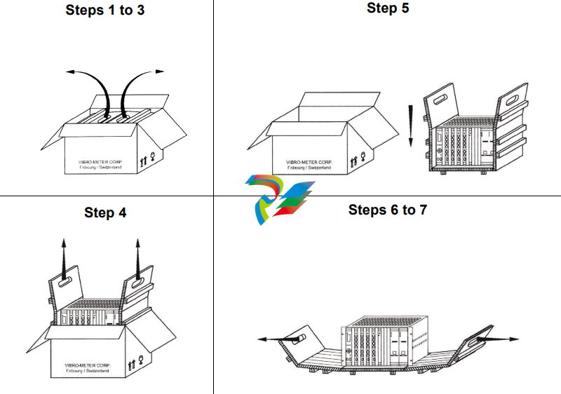
The procedure for unpacking VM600 MPS hardware is shown in Figure 1-1 and described
below:
Figure 1-1: Procedure for unpacking and inspecting VM600 MPS hardware
Step 1: Place the outer box on a flat surface with the arrows on the side of the box
pointing upwards.
Step 2: Open the outer box along the tape using a pair of scissors.
Step 3: Pull the handles of the inner box outwards to a vertical position.
Step 4: Gently lift the inner box vertically out of the outer box using the handles of the
inner box.
Step 5: Place the inner box on a flat surface.
Step 6: Open the inner box using the handles.
Step 7: Inspect the VM600 MPS hardware to ensure that no damage has occurred
during delivery

If damage has occurred to VM600 MPS hardware during delivery, please contact
your nearest Meggitt representative.
1.2 System overview
The VM600 machinery protection system (MPS) is a digital machinery protection system
designed for use in industrial applications. It is intended primarily for vibration monitoring to
assure the protection of rotating machinery as used in, for example, the power generation,
petro-chemical and petroleum industries as well as in marine related applications.
The VM600 series of machinery protection and condition monitoring systems from Meggitt’s
Vibro-Meter® product line are based around a 19″ rack containing various types of cards,
depending on the application.
There are basically two types of system:
• VM600 machinery protection system (MPS – 1U or 6U rack).
• VM600 condition monitoring system (CMS – 1U or 6U rack).
It is also possible to integrate MPS and CMS hardware into the same VM600 rack (ABE04x).
NOTE: This manual describes machinery protection system (MPS) hardware only.
Further information on condition monitoring system hardware can be found in the
VM600 condition monitoring system (CMS) hardware manual.
In its most basic configuration, a VM600 machinery protection system (MPS) consists of the
following hardware:
1- VM600 rack: 19″ system rack x 6U (ABE04x) or 19″ slimline rack x 1U (ABE056)
NOTE: ABE04x refers to both the ABE040 and ABE042, which are identical apart from the
position of the rack mounting brackets.
2- RPS6U rack power supply (ABE04x only)
When an AC-input version of the RPS6U is installed in a VM600 rack, the optional ASPS
auxiliary sensor power supply can be used to replace external power supplies such as
the APF19x 24 VDC power supplies.
3- MPC4 machinery protection card
4- IOC4T input/output card for the MPC4
5- AMC8 analog monitoring card
6- IOC8T input/output card for the AMC8.
The MPC4 and IOC4T cards form an inseparable card pair and one cannot be used without
the other. These cards are used primarily to monitor vibration for the purposes of machinery
protection.
Similarly, the AMC8 and IOC8T cards form an inseparable card pair and one cannot be used
without the other. These cards are used primarily to monitor quasi-static parameters such as
temperature, fluid level or flow rate for the purposes of machinery protection.
In general, a VM600 rack used for machinery protection can contain:
• Only MPC4 / IOC4T card pairs
• Only AMC8 / IOC8T card pairs
• A combination of MPC4 / IOC4T and AMC8 / IOC8T card pairs.
Depending on the application, the following type of cards can also be installed in the VM600
rack (ABE04x or ABE056):
7- RLC16 relay card (16 relays) and IRC4 intelligent relay card (eight relays combined as
either 4 DPDT or 8 SPDT).
All the above items can be used to make a stand-alone MPS system, that is, one that is not
connected to a network.
A networked version of the MPS will in addition contain the following hardware in the VM600
rack (ABE04x):
8- CPUM modular CPU card
9- IOCN input/output card for the CPUM.
Depending on the application (and irrespective of whether the rack is used in a stand-alone
or a networked configuration), one or more of the following power supplies can be used
outside a VM600 rack (ABE04x):
• APF19x 24 VDC power supplies
• Any equivalent low-noise power supply provided by the customer.
These devices must be used for GSI1xx galvanic separation units, GSV safety barriers and
transducer and signal conditioner front-ends having a current requirement greater than
25 mA. They will often be mounted in the cubicle in which the rack is installed.
NOTE: Auxiliary sensor power supplies (ASPSs) installed in a VM600 rack (ABE04x)
perform the same function as external power supplies such as the APF19x 24 VDC
power supplies. That is, they are used to power external hardware such as GSI
galvanic separation units or signal conditioners that require more power than can
be provided by an MPC4 / IOC4T card pair.
NOTE: Refer to the individual data sheets for full technical specifications of the MPS
hardware.
Finally, a combined machinery protection and condition monitoring system can integrate the
following condition monitoring hardware in the VM600 rack (ABE04x):
• XMx16/XIO16T extended monitoring card pairs.
NOTE: Further information on the condition monitoring system hardware can be found in
the VM600 condition monitoring system (CMS) hardware manual.
Figure 1-2 and Figure 1-3 show front and rear views of a typical VM600 rack (ABE04x)
containing machinery protection system (MPS) hardware.
NOTE: Refer to the data sheets for full technical specifications of the VM600 MPS
hardware (rack, cards and modules).
1.3.1 Ventilation
VM600 racks do not contain any ventilation units (fans). They therefore rely on either forced
ventilation by fans in the cabinet or on natural ventilation (convection) for their cooling. All
require the free flow of air in an upward direction, with air entering the rack through the vents
in the base of the rack and leaving it through the vents on the top of the rack.
When racks are installed in a cabinet or enclosure, in which natural ventilation is used, a
space of at least 50 mm should be present below and above each rack for an ABE04x rack
(see Figure 1-6, Case A).
It is possible to prevent warm air flowing from one rack to another, by placing inclined plates
between them in order to deflect the airflow (see Figure 1-6, Case B). When inclined plates
are used with VM600 racks, an inclined plate can also function as a non-flammable
separation barrier, if required (see 1.3.4 Instructions for locating and mounting). In addition,
the space of 50 mm should be present below and above ABE04x.
If an ABE04x rack is assembled without empty slots between the MPS and/or CMS
processing cards, it is recommended to use forced ventilation if the temperature of the air
flowing through the rack exceeds 40°C. If a 19” x 6U rack has at least one empty slot between
each processing card, it is recommended to use forced ventilation if the temperature of the
air flowing through the rack exceeds 55°C.
In a case where forced ventilation by fan units is used, the spacing above, below and between
racks can be reduced to zero, providing that the airflow to/from neighbouring racks is
ensured.
Always ensure adequate spacing (minimum 50 mm for ABE04x racks) is
provided below and above the rack to allow proper natural ventilation.
Failure to adhere to this requirement will cause overheating of the rack and
as a consequence will affect the correct operation of the system.
HAZARDOUS TEMPERATURES CAN EXIST WITHIN AND ON VM600 SYSTEM
RACKS (ABE04X).
DEPENDING ON THE AMBIENT OPERATING TEMPERATURE, NUMBER OF CARDS AND
POWER SUPPLIES INSTALLED (AND THEIR CONFIGURATION AND OPERATION), THE
INSTALLATION AND COOLING (FORCED OR NATURAL VENTILATION), THE TOP OF A
VM600 RACK CAN BECOME HOT AND THERE IS THE RISK OF BURNING WHEN HANDLING
THE RACK.
SEE ALSO HOT SURFACES AND THE RISK OF BURNING ON PAGE XVII.
1.3.2 Circuit breaker
In some circumstances the operator must ensure a switch or circuit breaker is provided in
order to comply with the IEC/EN 61010-1 standard. This standard stipulates that permanently
connected equipment (such as a VM600 ABE04x rack) must employ a switch or circuit
breaker as a means of disconnection from the mains supply.
A VM600 rack using the AC-input version of the RPS6U rack power supply already have an
ON/OFF switch or switches (and a fuse or fuses) at the rear of the rack. However, this is not
the case for the DC-input versions of the RPS6U rack power supply, so an appropriately rated
external circuit breaker or equivalent must be used.
1.3.3 Supply wiring
A VM600 rack using the AC-input version of the RPS6U rack power supply is supplied with a
mains power supply lead (power cord). Power supply rear panels with two AC inputs for
independent mains supplies are supplied with two mains cables. However, no lead (cable) is
supplied with a VM600 rack using the DC-input version of the RPS6U.
NOTE: Refer to the VM600 RPS6U rack power supply data sheet and VM600 system rack
(ABE04x) data sheet for further information on the mains power supply lead (power
cord) supplied with a VM600 rack.
For a VM600 rack using a DC-input version of the RPS6U rack power
supply, the mains power supply lead (power cord) linking the VM600 rack
to the mains supply must pass through an external switch or circuit
breaker.
The switch or circuit breaker must be installed and used in accordance with
the manufacturer’s instructions in order to ensure the correct and reliable
protection of the VM600 rack.
The switch or circuit breaker must be chosen in accordance with the
version of the DC-input RPS6U rack power supply used, and in particular
the maximum permitted input current and output power.
The operator must have easy access to the switch or circuit breaker at all
times.
For further information, refer to the VM600 machinery protection system
(MPS) hardware manual.
In general, for a VM600 rack, the mains power supply lead (power cord)
used must be of sufficient cross-section to meet the power requirements of
the connected equipment.
In addition, the power supply lead (power cord) must meet certain
requirements depending on whether it is used with an AC-input version or
a DC-input version of the RPS6U rack power supply.
For further information, refer to the VM600 machinery protection system
(MPS) hardware manual.
The AC-input rear panels with mains sockets used by VM600 racks have a power entry
module that requires temperature derating when a rack operates in environments with
temperatures greater than 50°C.
NOTE: Refer to the VM600 machinery protection system (MPS) hardware manual for
further information on the temperature derating required for AC-input rear panels.
1.3.4 Instructions for locating and mounting
A POPULATED VM600 SYSTEM RACK WITH CARDS AND RACK POWER SUPPLIES
INSTALLED IS A HEAVY OBJECT.
DEPENDING ON THE NUMBER OF VM600 CARDS AND RPS6U RACK POWER SUPPLIES
INSTALLED, A VM600 SYSTEM RACK (ABE04x) CAN BE TOO HEAVY TO LIFT, LOWER
OR OTHERWISE HANDLE MANUALLY BY A SINGLE PERSON AND THERE IS THE RISK OF
INJURY DURING INSTALLATION OR REMOVAL.
SEE ALSO HEAVY OBJECTS AND THE RISK OF INJURY ON PAGE IX.
The positioning of the VM600 rack shall allow easy access to the on/off
switch for the main supply.
A fully equipped VM600 rack can weigh 23 kg, so the following instructions
apply:
• Two people are required to carry or mount the VM600 rack in its cabinet.
• Shelves, guide rails and other devices used to support a VM600 rack must
be strong enough to bear the weight of the rack.
For the standard version (PNR: 204-040-100-0xx), separate-circuits version
(PNR: 204-040-100-1xx) and rear-mounting version (PNR: 204-042-100-0xx)
of the VM600 rack, deflection plates (barriers) must be installed both above
and below the VM600.
The barriers installed above and below a VM600 rack are required to
prevent unintentional access to the equipment in order to help reduce the
risk of electrical shock.
In addition, the barrier installed below a VM600 rack is also required in
order to help prevent the spread of fire in the unlikely event that one should
occur. Accordingly, the barrier below a VM600 must be a non-flammable
separation barrier made of metal or a UL94 V-1 rated (or better) material.
See also ELECTRICAL SAFETY AND INSTALLATION ON PAGE VIII.
When inclined plates are used with a VM600 rack in order to deflect airflow
and prevent warm air flowing into a rack, an inclined plate can also function
as a required deflection plate (barrier) if it is made from an appropriate
material. See 1.3.1 Ventilation.
Connecting power
For a typical VM600 MPS rack (ABE04x), the following versions of RPS6U rack power supply
are available:
• RPS6U power supply for use with an external AC-mains supply.
• RPS6U power supplies for use with different external DC-mains supplies.
The RPS6U rack power supply must be used with an appropriate connection panel mounted
at the rear of the VM600 rack. Several types of these associated rear panels exist
(see 1.4.2 DC-input rear panels, 1.4.3 AC-input rear panels and 1.4.4 Combined AC-input
and DC-input rear panels) in order to allow the connection of external AC-mains and/or
DC-mains power to the rack.
NOTE: For further information, refer to the VM600 RPS6U rack power supply data sheet.
As shown in Figure 1-4, one or two RPS6U power supplies can be installed in a VM600 rack
(ABE04x). When two RPS6Us are installed in a rack, the RPS6U on the right (slots 18 to 20)
is power supply 1 (PS1) and the RPS6U on the left (slots 15 to 17) is power supply 2 (PS2).
A rack can have two RPS6U power supplies installed for different reasons:
• In order to support rack power supply redundancy.
• In order to supply power to the cards (non-redundantly).
NOTE: A VM600 rack configuration with two RPS6U power supplies (330 W) operating
non-redundantly to supply power to the cards is typically only necessary for a full
rack of cards in an application where the operating environment requires RPS6U
output power derating.
The number and type of RPS6U power supplies installed in a VM600 rack, together with the
number of cards installed and the environmental conditions, helps determine the mode of
operation of the RPS6U power supplies as either redundant or non-redundant.
NOTE: For further information on RPS6U power supply configurations, including
‘redundant’ configurations, refer to the VM600 machinery protection system (MPS)
hardware manual.
To connect power to a VM600 rack:
• Determine the type of RPS6U rack power supply or supplies used by the VM600 rack:
DC-input, AC-input or both (that is, 1 x DC-input and 1 x AC-input).
See 1.4.1 Front panels.
• Connect the external mains power supply to the VM600 rack via the DC-input rear
panel(s) and/or AC-input rear panel(s), or combined AC-input and DC-input rear panel
using appropriate mains power supply leads (power cords).
See 1.4.2 DC-input rear panels, 1.4.3 AC-input rear panels and 1.4.4 Combined
AC-input and DC-input rear panels.
1.4.5 Power supply check relay
The power supply check relay provides an indication that the +5 V, +12 V and −12 V supplies
are being correctly generated and delivered by the RPS6U rack power supply or supplies to
the VM600 system rack (ABE04x) backplane. The connector for the power supply check relay
is available at the rear of the rack, on the rear panel associated with the RPS6U power supply
or supplies.
NOTE: Refer to the VM600 system rack (ABE040 and ABE042) data sheet for further
information on the power supply check relay.
As shown in Figure 1-12, the connector for the power supply check relay has three pins that
provide access to the relay contacts, defined from left to right as COM, NO and NC.
Apart from the power supply check relay connector, the other components shown in
Figure 1-12 are mounted on the VM600 rack (ABE04x) backplane.
THE POWER SUPPLY CHECK RELAY IS SPECIFIED FOR OPERATION WITH SEPARATED
OR SAFETY EXTRA-LOW VOLTAGE (SELV) SYSTEM VOLTAGE LEVELS:
• MAXIMUM SWITCHING VOLTAGE OF ±30 VRMS / ±42.4 VAC(PEAK) OR 60 VDC
Handling cards
1.5.1 Card locations
The VM600 MPS rack (ABE04x) is a modular system with 21 card (VME) slots, designated
slot 0 to slot 20 (from left to right, as seen from the front). See Figure 1-4.
The front and rear card cages of the rack are partitioned by a backplane. Each side of the
back plane is equipped with connectors allowing modules and cards to be quickly and easily
installed.
The following elements are connected to the backplane by installing them from the front of
the rack:
• AMC8 analog monitoring card
• CPUM modular CPU card
• MPC4 machinery protection card
• RPS6U mains power supply unit
The following elements are connected to the backplane by installing them from the rear of the
rack:
• IOC4T input/output card, for use with the corresponding MPC4
• IOC8T input/output card, for use with the corresponding AMC8
• IOCN input/output card, for use with the corresponding CPUM
• IRC4 intelligent relay card
• RLC16 relay card.
If the ABE04x rack is intended for use as a condition monitoring system (CMS) as well as an
machinery protection system (MPS), it can contain additional hardware:
• XMx16/XIO16T extended monitoring card pairs.
NOTE: Further information on the condition monitoring system hardware can be found in
the VM600 condition monitoring system (CMS) hardware manual.
Operating personnel should remember to observe the handling
precautions mentioned in Handling precautions for electrostatic sensitive
devices on page x when handling cards.
Failure to do this may result in cards becoming damaged by electrostatic
discharges.
Before inserting a card in a rack, visually check that none of the connector
pins are ben
Communicating with a VM600 MPS
The VM600 MPS may be configured in several ways, depending on the hardware installed in
the VM600 rack (ABE04x). Figure 1-13 shows the various possibilities for communicating
with the system. In all cases, one of the VM600 MPSx software packages (MPS1 or MPS2)
is required to perform the configuration.
Figure 1-13 (a) shows the simplest VM600 MPS configuration. This is a stand-alone rack, that
is, one not containing a CPUM card. In this case, each MPC4 or AMC8 card in the rack must
be programmed individually from a personal computer over an RS-232 link
(see 1.7 Connecting to a computer).
Figure 1-13 (b) shows a rack containing a CPUM modular CPU card. An Ethernet link may
be established between the personal computer and the VM600 MPS via this card. The
connection is made on the front panel of the CPUM, hence at the front of the rack.
Communication between the CPUM and the MPC4 / IOC4T or AMC8 / IOC8T card pair takes
place over a VME bus on the rack backplane.
Figure 1-13 (c) shows a rack containing a CPUM modular CPU card and the corresponding
IOCN input/output card. A connection may be established between the personal computer
and the VM600 MPS via the IOCN. The connection is made on the IOCN panel, hence at the
rear of the rack. Communication between the CPUM / IOCN card pair and the MPC4 / IOC4T
or AMC8 / IOC8T card pair takes place over a VME bus on the rack backplane.
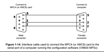
Connecting to a computer
The MPC4 and AMC8 cards have 9-pin D-sub RS-232 connectors. This can be used to
configure cards in a stand-alone rack. This is achieved using an interface cable from a
personal computer running one of the VM600 MPSx software packages (MPS1 or MPS2).
Details of the interface cable connections are shown in Figure 1-14.
8 Software configuration
The configuration of individual channels on the MPC4 and AMC8 cards must be made using
software before the system can be used. One of the VM600 MPSx software packages (MPS1
or MPS2) should be used to do this once the rack is powered up. For a stand-alone rack, the
configuration can be downloaded from a computer to each MPC4 and/or AMC8 card in turn
via an RS-232 link (see 1.7 Connecting to a computer). Alternatively, if the rack contains a
CPUM card (and, optionally, its corresponding IOCN card), the configuration can be
downloaded over an Ethernet link.
The majority of parameters are normally configured in the factory before delivery. The user
is nevertheless able to modify certain parameters if required using one of the VM600 MPSx
software packages (MPS1 or MPS2).
NOTE: Refer to the VM600 MPS1 configuration software for machinery protection systems
software manual or VM600 MPS2 configuration software for machinery protection
systems software manual for further information.
1.8.1 Setting the IP address of the CPUM card
The IP address of the CPUM card must be defined for VM600 racks employing this type of
card (that is, networked racks).
Unless otherwise specified at the time of ordering, each CPUM card is given the IP address
of 10.10.56.56 in the factory before delivery of the system. However, it is strongly
recommended to change this IP address, which can be done using the CPUM Configurator
software or a terminal emulator program.
NOTE: Refer to the VM600 networking manual for further information.
OPERATING THE SYSTEM
This chapter provides a brief overview of the operation of VM600 machinery protection
system (MPS) hardware. Functional information is also given for certain elements, such as
connectors, LEDs and buttons.
NOTE: For further on VM600 cards, refer to the VM600 machinery protection system
(MPS) hardware manual.
2.1 Card features and operation
2.1.1 MPC4 machinery protection card
Figure 2-1 shows an MPC4 machinery protection card and describes the meaning of the
card’s LEDs.
An MPC4 card has the following connectors:
• BNC connectors RAW OUT 1 to RAW OUT 4
• BNC connectors TACHO OUT 1 and TACHO OUT 2
• RS-232 connector.
NOTE: For information on communicating with an MPC4 card, see 1.7 Connecting to a
computer.
An MPC4 card has the following front panel LEDs:
• One global DIAG/STATUS indicator for the MPC4 / IOC4T card pair
• Status indicators for the four measurement channels and the 2 rotational speed
channels.
2.1.2 IOC4T input/output card
Figure 2-2 shows an IOC4T input/output card (required by MPC4 cards) both a) without
mating connectors and b) when mating connectors are inserted. It also describes the
meaning of the card’s LED.
An IOC4T card has three connectors: J1, J2 and J3 and a slot error indicator LED on the front
panel.
2.1.5 CPUM modular CPU card
Figure 2-5 shows the elements of an CPUM modular CPU card, describes their purpose and
gives an enlarged view of the display.
A CPUM card has the following elements on its front panel:
• A display with potentiometer to adjust contrast
• RS-232 connector
• Ethernet connector
• Three status LEDs
• Diagnostic LED
• Slot selection buttons
• Alarm reset button.
NOTE: For information on communicating with a CPUM card, see 1.7 Connecting to a
computer.
2.1.6 IOCN input/output card
Figure 2-6 shows the elements of an IOCN input/output card (optional for CPUM cards) and
describes their purpose.
An IOCN card has the following connectors:
• RS connector (type RJ11)
• Two serial communications connectors for the Modbus/RTU communication protocol
(group A)
• Two serial communications connectors for the Modbus/RTU communication protocol
(group B)
• Two Ethernet connectors.
2.1.7 RLC16 relay card
Figure 2-7 shows an RLC16 relay card both a) without mating connectors and b) with mating
connectors.
2.1.8 IRC4 relay card
Figure 2-7 shows an IRC4 relay card both a) without mating connectors and b) with mating
connectors.
The screw-terminal connectors of an RLC16 relay card can be connected to
hazardous voltages (up to 250 VAC nominal rate voltage).
Refer to the VM600 machinery protection system (MPS) hardware manual
and observe all safety instructions before installing and using RLC16 relay
cards.
The screw-terminal connectors of an IRC4 relay card can be connected to
hazardous voltages (up to 250 VAC nominal rate voltage).
Refer to the VM600 machinery protection system (MPS) hardware manual
and observe all safety instructions and before installing and using IRC4
relay cards
COMMON MAINTENANCE PROCEDURES
This chapter provides a brief overview of common maintenance procedures for VM600
machinery protection system (MPS) hardware. Information is provided on the replacement
and configuration of cards.
NOTE: For further information on replacing VM600 cards, refer to the VM600 machinery
protection system (MPS) hardware manual.
3.1 Replacing cards
Certain precautions must be observed when replacing cards.
3.1.1 Hot swapping
The following cards have ‘hot swapping’ capability, that is, they can be removed from and
inserted into a VM600 MPS (ABE04x) rack while it is powered up (a technique also known as
‘live insertion’):
• MPC4 and its associated IOC4T card
• AMC8 and its associated IOC8T card
• RLC16
• RPS6U.
A single RPS6U rack power supply can be replaced in racks employing two such power
supplies to support rack power supply redundancy (see 1.4 Connecting power).
However, it is necessary to power down a VM600 MPS (ABE04x) rack before inserting or
removing any of the following cards or devices:
• CPUM
• RPS6U, in racks employing a single power supply.
HAZARDOUS VOLTAGES EXIST WITHIN VM600 SYSTEM RACKS (ABE04X), AS
INDICATED BY THE USE OF THE FOLLOWING WARNING LABEL ON THE EQUIPMENT:
SEE ALSO HAZARDOUS VOLTAGES AND THE RISK OF ELECTRIC SHOCK ON PAGE IX.
HAZARDOUS TEMPERATURES CAN EXIST WITHIN AND ON VM600 SYSTEM
RACKS (ABE04X), AS INDICATED BY THE USE OF THE FOLLOWING WARNING LABEL ON
THE EQUIPMENT:
SEE ALSO HOT SURFACES AND THE RISK OF BURNING ON PAGE IX.
When handling cards, the necessary precautions should be taken to
prevent damage due to electrostatic discharges.
See Handling precautions for electrostatic sensitive devices on page x for
further information.
Refer to the VM600 machinery protection system (MPS) hardware manual
and observe all safety instructions before replacing VM600 cards
Cards in a stand-alone rack
NOTE: The following remarks concern stand-alone racks. These do not contain a CPUM
card are not connected to a network.
For a stand-alone rack, hardware damage can occur if a card intended for slot mm is inserted
in slot nn.
NOTE: For further information on replacing VM600 cards in a stand-alone rack, refer to the
VM600 machinery protection system (MPS) hardware manual.
3.1.3 Cards in a networked rack
NOTE: The following remarks concern networked racks. These contain a CPUM card
(and, optionally, its associated IOCN card) and are connected to a network.
For a networked rack, if a card originally used in slot mm is inserted in slot nn, the CPUM card
recognises that the card’s configuration does not match the slot.
The behaviour of the CPUM card after it detects a change of configuration for a card depends
on:
• The version of the CPUM card’s firmware.
• And for CPUM firmware version 067 or later – the setting of the CPUM’s configuration
master parameter.
NOTE: For further information on replacing VM600 cards in a networked rack, refer to the
VM600 machinery protection system (MPS) hardware manual.
Because of this, a different MPC4, AMC8 or IRC4 card must only be installed
‘live’ and without reconfiguration if its configuration is known to be
identical to that of the card previously removed.
Because of this, problems can occur if a card taken from slot nn of rack x
is inserted into slot nn of rack y, as different slots can be used for totally
different functions in each rack.
This form of hot swapping should be avoided unless you are certain that
the cards in slot nn of each rack have exactly the same configuration.
More generally, if you do not know how a card is configured, you should not
install it until the configuration is known.
3.1.4 Hot swapping cards in a VM600 rack
See 3.1 Replacing cards before removing or inserting a card.
3.1.4.1 Hot swapping a card in the front of a VM600 rack
The procedure for hot swapping a card in the front of a VM600 rack is as follows.
In the front of the rack:
1- Disconnect the external cables connected to the card, if any.
2- Remove the card from the rack (see 3.1.4.3 Removing cards safely).
3- Insert the replacement card in the front of the rack.
4- Reconnect any cables to the card.
3.1.4.2 Hot swapping a card in the rear of a VM600 rack
The procedure for hot swapping a card in the rear of a VM600 rack is as follows.
First, in the front of the rack:
1- Remove any associated processing card in the corresponding slot in the front of the rack
from the rack’s backplane (see 3.1.4.1 Hot swapping a card in the front of a VM600 rack).
Then, in the rear of the rack:
2- Disconnect all external cables connected to the card.
3- Remove the card from the rear of the rack (see 3.1.4.3 Removing cards safely).
4- Insert the replacement card in the rear of the rack.
5- Reconnect all of the cables to the card.
Finally, in the front of the rack:
6- Reinsert the associated processing card in the corresponding slot in the front of the rack
(to the rack’s backplane).
3.1.4.3 Removing cards safely
The AMC8, MPC4, IOC4T, IOC8T, RLC16 and IRC4 cards all feature a lever mechanism to
help the user to easily remove the card. Follow the procedure below and see Figure 3-1):
1- Disconnect all external cables connected to the card, for example, the communication
cable (RS-232) for an MPC4 card or front-end cables (J1, J2 and J3) for an IOC4T card.
2- Unfasten the two captive fixing screws. These are found at the top and at the bottom of
the front panel.
3- With your thumbs, simultaneously push the upper handle upwards and the lower
handle downwards. These combined actions will cause the card to move forwards by
1 to 2 mm.
4- Pull on both handles together (with equal force) to extract the card from the rack.
NOTE: Remember to reconnect all of the cables after a card is replaced in the rack.
Before ‘hot swapping’ a card in the rear of a VM600 rack, any associated
processing card in the corresponding slots in the front of the rack must be
disconnected from the rack’s backplane.
Software configuration
The following procedure can be used to configure VM600 MPSx software after replacing a
card:
1- Disconnect the front-end components (that is, transducer, signal conditioner, probe and
cables) from the rack by unfastening the connectors on the IOC4T or IOC8T card
installed in slot nn.
2- Insert into slot nn the MPC4 or AMC8 card whose configuration you want to read.
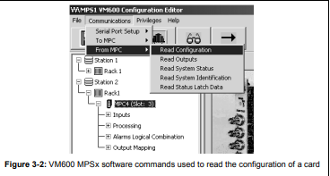
3- Use one of the VM600 MPSx software packages (MPS1 or MPS2) to read the
configuration of the card in slot nn
(Communications > From MPC > Read Configuration).
See example in Figure 3-2, in which the card in slot 3 is selected.
4- Modify the card configuration if necessary using the VM600 MPSx software.
5- Use one of the VM600 MPSx software packages (MPS1 or MPS2) to send the (modified)
configuration to the card in slot nn
(Communications > To MPC > Send Configuration).
6- Reconnect the front-end components to the connectors on the IOC4T or IOC8T card
installed in slot nn.
SERVICE AND SUPPORT 4.1 Contacting us Meggitt Sensing Systems’ worldwide customer support network offers a range of support, including 4.2 Technical support and 4.3 Sales and repairs support. For customer support, contact your local Meggitt representative. Alternatively, contact our main office: Meggitt SA Customer support department Route de Moncor 4 PO Box 1616 1701 Fribourg Switzerland Telephone: +41 26 407 11 11 Email: energysupport@ch.meggitt.com Website: www.meggittsensing.com/energy 4.2 Technical support Meggitt Sensing Systems’ technical support team provide both pre-sales and post-sales technical support, including: 1- General advice 2- Technical advice 3- Troubleshooting 4- Site visits. NOTE: For further information, contact us (see 4.1 Contacting us). 4.3 Sales and repairs support Meggitt Sensing Systems’ sales team provide both pre-sales and post-sales support, including advice on: 1- New products 2- Spare parts 3- Repairs. NOTE: If a product has to be returned for repairs, then it should be accompanied by a completed Energy product return form. See 4.4 Repairs and returns. 4 – 2 VM600 MPS quick start manual MAMPS-QS/E Edition 2 – October 2018 Repairs and returns SERVICE AND SUPPORT 4.4 Repairs and returns If a Meggitt Vibro-Meter® Energy product needs to be returned to Meggitt Switzerland, please use the online Energy product return procedure on the Meggitt Vibro-Meter® website at www.meggittsensing.com/energy/service-and-support/repair NOTE: For further information, refer to the VM600 machinery protection system (MPS) hardware manual or contact us (see 4.1 Contacting us). 4.5 End-of-life product disposal VM600 machinery protection system (MPS) hardware is an electrical/electronic product, therefore, it must be disposed of in a acceptable manner at the end of its useful life. This is important in order to reduce pollution and improve resource efficiency. NOTE: At the end of its useful life, a VM600-rack based monitoring system must be disposed of in an environmentally friendly manner. In European Union Member States, the WEEE directive is applicable. In other countries and regions of the world, different laws and regulations may be applicable, so please consult your local authorities. NOTE: For further information, refer to the VM600 machinery protection system (MPS) hardware manual or contact us (see 4.1 Contacting us).
Leave a comment
Your email address will not be published. Required fields are marked *