VM600 First-Generation:
One module does it all
When vibro-meter introduced
the VM600 architecture in 2000,
it represented a dramatic leap
forward that sent shockwaves
through the industry with numerous
innovative features.
The most notable of these was
the simplicity of an architecture
that used a single card type – the
MPC4 – to address all channel
types except temperature. Prior
architectures, and the prevailing
model embraced by every other
leading manufacturer of the time,
was a reliance on a large diversity
of module types. For example, one
well-known manufacturer required
more than 20 different module
types in their system to achieve
the full complement of all available
functionality.
Compounding the issue, each
monitor module type had as many
as 3 different corresponding I/O
module variations. The spare
parts implications were significant
– along with the widely varying
costs of each module depending
on the channel types supported.
It was a complex architecture with
a complex diversity of modules, a
complex pricing structure, and a
complex spare parts burden.
In contrast, the VM600 required
only 4 basic card types (power,
communications, temperature, and
universally configurable vibration)
for comprehensive machinery
protection, each with only a single
type of corresponding I/O module.
In a word, the system was uniquely
simple – without sacrificing
functionality. It also introduced
the concept of combining speed
/ phase reference measurements
on a single module as auxiliary
channels.
This allowed four channels of
vibration and two channels of
tachometer and/or phase reference
to be addressed in a single rack
slot via the MPC4 (Machine
Protection Card – 4 channel).
In fact, it perhaps would have been
better named “MPC4+2” for this
very reason
.
In addition, 4 relays were included
on each MPC4, turning a single
module into a fully self-contained
monitor with all required protective
functions. Hence, the slogan “one
module does it all” aptly described
the workhorse of the system: the
MPC4 module that provided true
“universal” programmability for all
required vibration channel types
and sensors.
The VM600 was introduced in
2000 and required only 4 basic
module types for comprehensive
machinery protection functionality:
power, temperature, vibration, and
communications.

Segregated condition monitoring
Another key innovation of the
first-generation architecture was
entirely segregated, 16-channel
condition monitoring (CM)
modules that ensured machinery
protective functions could never
be compromised by failures in the
condition monitoring hardware,
yet resided in the same rack
chassis and could share input
signals with the MPC4 protective
modules – or use entirely separate
inputs if desired. Two CM module
types were available – one for
vibration (XMV16) and one for
gas turbine combustion dynamics
(XMC16). Other manufacturer’s
platforms of the era used highly
integrated condition monitoring
that co-mingled protective and
CM functions, resulting in a level
of integration that amplified rather
than attenuated vulnerabilities.
The VM600’s first-generation
architecture physically separated
condition monitoring from
protection by using separate
modules – the MPC4Mk1 for
protection and the XMV16 for
condition monitoring. A variant
of the XMV16 (the XMC16) was
used for combustion dynamics
monitoring on low-NOx gas
turbines.
As gas turbine firing temperatures
increased in the 70s, 80s, and 90s
to achieve greater efficiencies,
these efficiencies came at the
expense of increased NOx
emissions. It was not long before
environmental concerns demanded
these increased NOx emissions
be reduced, and new combustor
technology emerged as a result,
referred to as Dry Low NOx
(DLN) or Dry Low Emissions (DLE)
designs1
.
Although these designs did indeed
reduce NOx emissions, they
entailed so-called “metastable”
combustion conditions that could
impose extremely damaging
dynamic pressure pulsation forces
on the combustor2
. If not very
carefully monitored and controlled,
combustor life could be severely
degraded.
It was out of this fundamental
need that gas turbine combustor
monitoring emerged.
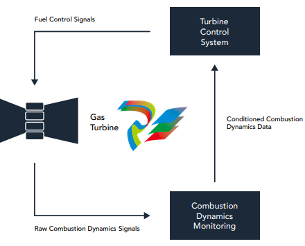
The concept is quite simple: adjust
the fuel/air mixture to be as lean
as possible, but not so lean as
to introduce an unstable flame
and the accompanying dynamic
pressure pulsations that will
prematurely age (or destroy) the
combustor.
Using highly specialized hightemperature pressure sensors, the
pressure inside each combustor
is monitored for the presence of
these damaging pulsations and the
fuel/air ratio is continually adjusted
using a closed feedback loop
between the dynamic pressure
sensing system and the turbine
control system where the fuel/air
mixture is adjusted.
When pulsations are detected,
the flame is unstable and the
mixture is too lean. The ratio is
then adjusted (less lean) such that
the combustor is perpetually on
the verge of instability, but without
actually pulsating. In other words,
a precisely controlled balancing act
to maintain that tiny operational
zone existing between stable and
unstable combustion – a zone
where efficiency is highest and
NOx emissions lowest.
It turns out that monitoring these
pressure pulsations requires
sophisticated filtering and other
signal processing that is not unlike
the requirements of monitoring a
vibration signal – particularly those
from aeroderivative gas turbines
where accelerometers are used and
extraction of desired signal features
can be very demanding.
It was not surprising, then, that
gas turbine manufacturers turned
to vibration monitoring suppliers
to meet these needs. Vibro-meter
was among the first to rise to the
challenge and offer fully integrated
combustion dynamics monitoring
with the release of our VM600
platform and its 16-channel XMC16
module.
Indeed, the deep domain expertise
of Meggitt for supplying sensors
that can survive environmental
extremes meant that vibrometer could supply not only the
necessary monitoring system, but
the associated high-temperature
dynamic pressure sensors, able to
survive in one of the most extreme
of all machinery environments:
gas turbine combustors where
conditions at the measurement
locations can approach 700°C and
250 bar.
1. Zink, John C., “Progress
continues in gas turbine NOx
control” Power Engineering. May
1, 1996. Retrieved September 19,
2021.
2. Richards, G A, and Lee, G T. “Gas
turbine combustion instability”.
US Dept of Energy. September 1,
1996. Retrieved September 19,
2021.
Combustion dynamics monitoring
is part of closed-loop control to
ensure that damaging pulsations
in low-NOx gas turbines do not
prematurely age or destroy the
combustor cans. The pulsations
occur because today’s lowNOx technologies rely on
inherently metastable combustion
conditions that burn fuel in the
leanest possible manner but can
produce an unstable flame if not
meticulously controlled
Full API 670 compliance
Within the petrochemical sector, the importance of American Petroleum
Institute standards for machinery and its associated instrumentation
cannot be overstated.
These standards are no longer considered best practice employed by the
cutting-edge few – they are so universally accepted that they are today
considered standard practice and thus widely embraced by the many.
Nowhere is this more true than with API Standard 67023 which defines the
necessary attributes of machinery protection systems.
The first edition of this standard was released in 1976 and has been so
successfully embraced that it has resulted in five successive revisions to
keep pace with industry’s changing needs: the 6th edition of the standard
is currently in preparation and is expected to be released by 2023.
Indeed, it provides such value that it has remained among the API’s bestselling standards in the more than 45 years since its introduction. Not
surprisingly, the VM600 was designed with full API 670 compliance in
mind, allowing customers in the oil & gas industries to employ the system
with the confidence that it rigorously adheres to the robust feature set
and functionality that multiple generations of users and manufacturers
have found important.
Indeed, the requirements of 670 are so well-recognized by practitioners
in all industries that it is not uncommon to find power generation
and other customers using it as the basis of their own purchasing
specifications – not just those in the petroleum industries.
3. API Standard 670 “Machinery Protection Systems”. American Petroleum
Institute. Washington, DC. November 2014.
Full API 670 compliance
Both first- and second-generation
VM600 platforms are fully
compliant with the 5th edition
of API 670. Additionally, we
participate on the API Task Force
that is currently preparing the 6th
edition to ensure we remain fully
compliant with and abreast of
industry changes as the standard
evolves.

Why a Second-Generation product?
With such a rich feature set and pedigree of innovation, it is natural to ask
why a second-generation platform was even necessary.
There are multiple reasons:
Cybersecurity
When the VM600 was originally
designed, the internet itself
was not even a decade old. The
idea that this global network
infrastructure would someday
become a remotely accessible
means to sabotage industrial
instruments and automation
systems wasn’t even part of
anyone’s thought process at the
time. But the intervening 22 years
have changed everything.
Today, cybersecurity is at the very
top of customer concerns. What
has also changed are the types
of customers concerned about
cybersecurity. For decades, the
most innovative and demanding
customers were largely in the
petroleum and oil & gas sectors.
They were often the ones with
remote facilities – such as offshore
platforms – where remote access to
data was in highest demand.
For years, they had led the way
in the defining the features and
functions required of condition
monitoring and machinery
protection platforms because their
processes were often worth millions
of dollars per hour and machinery
failures were potentially so costly.
As such, they were the ones with
the most sophisticated needs and
the deepest pockets to address
those needs.
But then, the world began to
shift as the most pressing needs
began to fall within the power
generation sector along with
corresponding expenditures to
ensure cybersecurity therein.
Where a cyberattack might be
able to bring down a single
petrochemical facility, a similar
attack could potentially bring down
major portions of the electrical
grid in a country, affecting tens of
millions of people for days.
The Northeast blackout of 20034
,
for example, left 55 million
people in the US and Canada
without power – some for as long
as two weeks. A similar event
in Europe just a few months
later left 56 million people in
Italy and Switzerland without
power5
. Moving to the southern
hemisphere, a 1999 event in Brazil
lasted more than three months and
impacted 97 million people. And
a 2012 blackout event in India7
affected more than half a billion
people for two days. The point
here is that cyber vulnerabilities
in the power generation sector
are particularly serious because
they may not necessarily
isolate themselves to a single
facility; because the generation,
transmission, and distribution
infrastructure is interconnected
via a grid, an attack can impact
huge portions of the electrical
grid for days, weeks, or months at
a time. This also impacts critical
infrastructure such as hospitals,
law enforcement, banking, water
utilities, grocery stores, petrol
stations, and other entities that
depend on electrical power to
deliver vital goods and services.
The stakes are indeed exceedingly
high.
Coupled with the realization that
an attack on the power grid had
such devastating implications,
industry began to face the reality
that cyberattacks were not just able
to exploit conventional computer
systems – they could exploit
industrial control and automation
platforms such as SCADA systems
and PLCs. In 2007, the Aurora
Generator Test8
conducted by
Idaho National Labs demonstrated
that it was possible to compromise
a protective system via the
internet and thereby destroy a
diesel generator within a mere 3
minutes. Several years later, the
Stuxnet9 worm showed the world
that an industrial cyberattack was
no longer just hypothetical – it had
actually been accomplished. Iran’s
nuclear program was sabotaged by
Stuxnet-infected PLCs, destroying
the enrichment centrifuges they
controlled by sending them into
overspeed conditions.
All of this is to underscore that
cybersecurity moved from not
even being on customers’ radar a
mere 15 years prior, to being their
number one concern by 2015.
While the VM600 had unwittingly
addressed a portion of these
concerns by entirely segregating
the protection functions from the
condition monitoring functions,
there were other aspects of the
system that represented cyber
vulnerabilities – vulnerabilities that
would require a new generation of
modules.
4 “Technical Analysis of the
August 14, 2003, Blackout: What
Happened, Why, and What Did We
Learn?”. North American Electric
Reliability Council. July 13, 2004.
Retrieved September 18, 2021.
5 “Report on the blackout in Italy on
28 September 2003” Swiss Federal
Office of Energy. November 2003. 6 “Wide Power Failure Strikes
Southern Brazil”. The New York
Times. March 12, 1999. Retrieved
September 18, 2021.
7 “India blackouts leave 700 million
without power”. The Guardian. July
31, 2012. Retrieved September 18,
2021.
8. “U.S. video shows hacker hit
on power grid”. USA Today.
September 27, 2007. Retrieved
September 18, 2021.
9. Kushner, David. “The Real
Story of Stuxnet”. ieee.org. IEEE
Spectrum. February 26, 2013.
Retrieved September 18, 2021.
Integration
While the separation between
protection and condition
monitoring in the legacy VM600
architecture was desirable from
the standpoint of cybersecurity, it
was not optimal in other respects.
In particular, because there was
no communication at all between
the condition monitoring and
protection environments, it was
cumbersome to see the status of
the protection system alarms from
within the condition monitoring
software.
Also, the same measurements
(such as overall amplitude or 1X
amplitude) were generated in each
path (protection and condition
monitoring) but could be slightly
different due to different circuitry in
different cards. Work-arounds were
available but the environments
for viewing protection and
condition monitoring statuses and
information were not truly unified.
Also, the system had to be
configured twice: once in the
protection environment and then
again in the condition monitoring
environment, without the ability
to reuse similar or identical
configuration settings from the
protection environment into the
condition monitoring environment.
Instead, the user had to manually
replicate the settings – not just
re-use the settings – such as
transducer types, full-scale values,
and even alarm setpoints.
Lastly, due to slight differences
in signal processing between the
protection hardware and condition
monitoring hardware, even
identical configurations could result
in slight discrepancies between the
timing of a protection alarm in the
MPC4 card and the emulation of
the same alarm in the XMV16 card.
While this timing was normally
not an issue, it could be more
cumbersome to create accurate
sequence-of-event reconstructions
because a protection alarm archive
had to be accessed separately
from a condition monitoring alarm
archive.
Clearly, in a next-generation
system, it would be important to
address the above issues
Component
Availability10
Users of machinery protection
systems generally expect a
lifecycle of 15-20 years for the
hardware along with a generous,
phased obsolescence period that
gives time to both plan and then
implement replacement of the
aging system.
During this time, spare parts must
still be available that maintain
hazardous area approvals and SIL
certifications. Simply substituting
newer electronic components
on circuit boards may seem like
an easy solution, but sometimes
there are no form/fit/function
replacements.
And even when there are, this
can often mean resubmittals to
approvals / certification agencies.
Eventually, the situation can
become unsustainable, even when
last-time buys of components are
secured in an attempt to meet
future demand. All of these can
represent a delicate balancing act
and finally the need to introduce a
new platform becomes inevitable.
However, manufacturers generally
view this as an opportunity to not
just replace systems, but to provide
additional functionality and value
because new customer needs have
arisen in the meantime. This has
certainly been the case with the
VM600 platform.
10. “Component Obsolescence
Management”. electronic-notes.
com. Retrieved September 19,
2021.
Deliberately
avoiding
“Rip and Replace”
One of the challenges inherent
in introducing a new platform
is to avoid “rip and replace”
requirements. No customer enjoys
being told that they must rip out
the old hardware in its entirety and
install new hardware.
This can be compounded when the
new system is so radically different
compared to its predecessor that
wiring connections cannot be
reused, panel cutout and mounting
dimensions must be modified,
different software must be used,
and even power and ventilation
requirements have changed. The
devil, as they say, is in the details.
From a manufacturer’s perspective,
“rip and replace” can also be
undesirable because it then
becomes just as easy and costeffective for customers to switch
to an entirely different supplier
as to remain with the incumbent.
For numerous reasons, it is thus
in everyone’s best interests when
the new platform represents
backwards compatibility with the
prior platform while introducing
necessary improvements to solve
the continually evolving list of
customer needs.
As vibro-meter set out to design
a second-generation version of
the VM600, we purposed that we
would not leave existing customers
stranded or inconvenienced by “rip
and replace” approaches.
but without depriving them of
the same feature and function
improvements available to
customers installing a system
for the first time. In other words,
existing customers should be
rewarded – not penalized – by the
release of a new system.
“More than 8,000
VM600 systems are
installed worldwide and
we owed it to those
customers to provide
them with a thoughtful
path forward that
allowed them to
retain as much of their
existing investment as
possible.“
The VM600Mk2
True to our promise, it does this
without stranding our customers
and their large installed base of
more than 8,000 VM600Mk1 systems
– systems that encompass 240,000
MPC4Mk1 protection channels and
88,000 CMC/XMV/XMC condition
monitoring channels.
Because the VM600Mk2 uses the
same backplane and power
supplies as its predecessor, it is
not necessary to replace a rack in
order to upgrade modules. This
also means that existing racks
can incorporate a mix of firstgeneration (Mk1) and secondgeneration (Mk2) modules if
desired, and that Mk2 modules
can be used as spares for Mk1
modules11,
12 if desired.
In addition, the XMC and XMV12
modules have not changed
and continue to provide worldclass capabilities for dynamic
combustion monitoring and
vibration condition monitoring,
respectively; we have simply
upgraded the faceplates for
aesthetic consistency with new
modules such as the MPC4Mk2
and CPUMMk2.
11. Mk2 modules are configured
using our VibroSight PROTECT
software; Mk1 modules are
configured using our MPSx
software. Also, MPC4Mk2 modules
can
only be paired with their associated
IOC4Mk2 input/output modules and
cannot use the existing IOC4T.
12. MPC4Mk2 modules retain the
ability to share input signals with
an associated XMV16 module,
but can also provide integrated
condition monitoring functionality
and thus entirely eliminate the
need for a separate condition
monitoring module for vibration
measurements.
Our second-generation VM600 platform retains all of the
innovation inherent in the first-generation product while
addressing evolving marketplace needs.
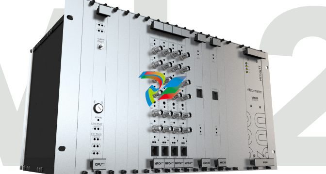
The Second-Generation VM600 retains the same chassis and power supplies, but delivers powerful new
modules with improved functionality and cybersecurity.
1 19” EIA chassis, 6U tall, 300mm deep, 21 slots (numbered 0-20).
2 CPUMMk2 Communications and rack control module; supports redundant media with communications with plant control and
automation platforms including PLCs, DCSs, turbine controllers, local displays, and more; supported protocols include Modbus TCP,
Modbus RTU*, Profibus DP, and Profinet*. Cybersecure design to meet IEC 62443.
3 Keylock provides an extra measure of physical security in addition to password-protected access to configuration changes.
4 MPC4Mk2 Universal vibration monitoring module provides 4 channels of dynamic signal inputs and 2 channels of speed/phase or DC
inputs; provides integrated protection and condition monitoring while delivering cybersecure performance to meet IEC 62443; up to
12 modules (72 channels) per rack.
5 The MPC4Mk2 is capable of specialized measurements such as generator air gap on hydroelectric units, combustion monitoring on
gas turbines
6 SIL 2 version of MPC4Mk2 modules. Five on-board relays allow alarm and module fault (OK) status annunciation, suitable for autoshutdown applications meeting SIL 2.
7 XMV16 module can be used for condition monitoring-only applications where protection is not required; allows 16 channels of highperformance condition monitoring in a single rack slot. Ideal for balance-of-plant assets, small hydro units where protection is not
required, or for adding condition monitoring to existing third-party protection systems.
8 XMC16 module provides robust gas turbine combustion dynamics monitoring in the same chassis as vibration protection and
condition monitoring.
9 RLC16Mk2 relay expansion module provides 16 additional relays to augment the 5 relays on board each MPC4Mk2 module.
10 Proprietary ethernet communications provide all dynamic and other rack signals to VibroSight software for archival, analysis, and
visualization.
11 Simplex or redundant power supplies deliver all required power for rack modules and connected sensors.
s no longer necessary to
use MPC4 cards for protection
and separate XMV1613 cards
for condition monitoring. The
functionality of the XMV16 is now
built-in to the new MPC4Mk2 cards.
Not only does this eliminate the
cost of unnecessarily redundant
hardware, it eliminates the
dissimilar-data issues inherent in
two separate signal processing
paths and alarm processing paths
that were noted in the section on
integration. Condition monitoring
can now focus on supplementary
signal processing and alarming
to augment the basic protection
system measurements – not recreating them.
This also speeds the configuration
process because the configuration
elements that are common to
both the protection and condition
monitoring systems no longer need
to be duplicated. Configuration
in the condition monitoring
environment thus adds to the basic
protection configuration. Alarms
and data are perfectly synchronized
between the two environments
and the condition monitoring
environment can be used to
visualize everything while allowing
an additional layer of alarming
for earlier warning on any desired
parameter – whether a parameter
from the underlying protection
system or a parameter created only
for use in the condition monitoring
environment.
13. When a VM600 rack is used
purely for condition monitoring,
such as when connected to a
separate machinery protection
system from another supplier, the
XMV16 module provides costeffective condition monitoring
functionality for 16 channels in a
single rack slot. MPC4Mk2 modules
and their associated machinery
protection functions are not
required.
The new MPC4Mk2 module (left) and
its companion I/O module (right)
provide integrated protection and
condition monitoring, eliminating
the need for a separate XMV16
module.
And while this integration makes
for a more powerful and efficient
VM600 platform, we have achieved
this without compromising
cybersecurity, as discussed next.
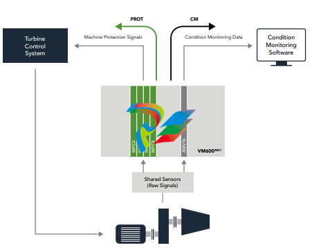
The new MPC4Mk2 module provides integrated condition monitoring functionality identical to that of a separate
XMV16 module, but in a manner that completely segregates the protective functions (black) from the condition
monitoring functions (gray). Like its predecessor, the same sensors can be shared between protective and
condition monitoring functions via the rack’s backplane.
Permanent Ethernet communication link
X
M
V16
MPC4
VM600rack
Condition
monitoring
Sensor
Machinery protection
configuration software
VibroSight condition
monitoring software
Machinery
protection
K
“Alarms and data are perfectly synchronized
between the two environments and the condition
monitoring environment can be used to visualize
everything while allowing an additional layer of
alarming.
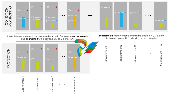
The new MPC4Mk2 cards allow
the measurements and statuses
to be shared with VibroSight
condition monitoring software
rather than requiring that they be
re-created therein. This eliminates
the problem of measurements and
statuses that do not exactly agree
between the two environments. It
also allows the user to augment the
underlying protection system data
with supplemental measurements
and alarms. In this diagram, the
capabilities of a single channel in
the MPC4Mk2 are depicted.
The protective alert (PA) and
protective danger (PD) alarms for
each measurement are shown in
orange and red, respectively. The
MPC4Mk2 is capable of generating
10 measurements and associated
alarms from each of its four
dynamic channels.
The VibroSight condition
monitoring system can then
augment these 10 measurements
with n additional measurements as
shown by 11 through 10+n in the
diagram. In addition, software-only
alarms (SA) can be implemented
for all measurements and allow
earlier warning on any desired
parameter than is available from
the protection hardware alone. In
the diagram, a software alarm is
present on Measurement 1 even
though no hardware alarms are
present.
On Measurement 10, a hardware
alarm is present (Alert) and is
identically annunciated in both
the protection and condition
monitoring environments.
Measurement 12 is supplemental
and does not appear in the
underlying protection system at all.
Not only is the measurement
available in the software, it has
also exceeded the software alarm
threshold and thus shows as
being in an alarm state. The other
supplemental measurements are
all green, indicating that they
are below their respective alarm
thresholds.
Leave a comment
Your email address will not be published. Required fields are marked *