Because of the variety of uses for the products described in this publication, those
responsible for the application and use of these products must satisfy themselves that all
necessary steps have been taken to assure that each application and use meets all
performance and safety requirements, including any applicable laws, regulations, codes
and standards. In no event will Quest Technical Solutions be responsible or liable for
indirect or consequential damage resulting from the use or application of these products.
Any illustrations, charts, sample programs, and layout examples shown in this publication
are intended solely for purposes of example. Since there are many variables and
requirements associated with any particular installation, Quest Technical Solutions does
not assume responsibility or liability (to include intellectual property liability) for actual
use based upon the examples shown in this publication.
Throughout this manual we use notes to make you aware of safety considerations.
WARNING!
Identifies information about practices or circumstances that can lead to
personal injury or death, property damage, or economic loss.
These warnings help to:
• identify a hazard
• avoid the hazard
• recognize the consequences
IMPORTANT! Identifies information that is especially important for successful
application and understanding of the product.
TIP Identifies information that explains the best way to use the
AN-X2-AB-DHRIO Gateway
Microsoft is a registered trademark of Microsoft Corporation.
Windows, Windows XP, Windows Vista and Windows 7 are trademarks of Microsoft Corporation.
ControlLogix, RSLinx and RSLogix 5000 are trademarks of the Allen-Bradley Company, Inc.
The RIO-ADPT communications module connects a ControlLogix PLC or other device
to an Allen-Bradley remote I/O network.
As an adapter, the module:
· has one remote I/O channel
· emulates one or more racks
· supports all remote I/O baud rates: 57.6, 115.2, 230.4 kbaud
· supports rack numbers from 0 to 76 octal
· supports all combinations of partial racks
· supports block transfers at all possible locations
· monitors discrete I/O and block transfer reads and writes on the same remote
I/O network
· updates all I/O via scheduled connections
The AN-X2-AB-DHRIO module is supplied with a Windows utility, AnxAbRioCfgAdpt,
for configuring and monitoring the remote I/O network and mapping the remote I/O data
to ControlLogix scheduled data.
The AN-X2-AB-DHRIO communicates with the ControlLogix processor using scheduled
connections over Ethernet. Remote I/O data is mapped into the scheduled input and
output data by the configuration program.
On monitored racks, a ControlLogix processor reads remote I/O inputs and outputs, and
data from block transfer reads and writes on the remote I/O network. All remote I/O data
is mapped to scheduled inputs in the ControlLogix.
On emulated (active) racks, a ControlLogix processor writes remote I/O inputs and block
transfer read data and reads remote I/O outputs and block transfer write data.
The AN-X2-AB-DHRIO module has a web interface for monitoring logs and performing
administrative functions. You can communicate with the module using any standard web
browser such as Internet Explorer.
The module firmware can be selected and updated using the web interface. Refer to page
57 for details
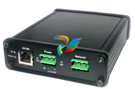
The module has:
• two LEDs to indicate the status of the connection to the Ethernet (100 and
Link/Act)
• a LED to indicate the module’s internal state and the state of communication with
the ControlLogix (SYS)
• a LED to indicate the state of communications on the Remote I/O network (NET)
• an Ethernet connector
• a power connector
• a 3-pin Phoenix connector to connect to the remote I/O network
A watchdog timer is implemented in the module’s hardware. If the firmware does not
kick the watchdog within the timeout period the watchdog times out and places the
module into a safe fatal failure state.
A jabber inhibit timer is implemented in the module’s hardware. If the network
transmitter is on longer than 150% of the longest network frame time, the transmitter is
forced off and the module is placed into a safe fatal failure state.
Package Contents
• AN-X2-AB-DHRIO module
• microSD to SD card adapter
• CD containing software and documentation
• rubber feet for desktop use
Identifying the AN-X2 versus the Original AN-X
The label on the bottom toward the front says AN-X2.
There is a slot at the back for the microSD card.
When initially powered up:
· AN-X2 railroads (alternates) SYS and NET LEDs green as it starts up
· without the Ethernet cable attached, the Ethernet 10/100 (upper) LED is on for ANX2 (both Ethernet LEDs are off for the original AN-X)
Differences from the Original AN-X
AN-X2 modules have a microSD card for storage of firmware and configuration data.
You no longer need AnxInit; everything can be done from the web interface or by editing
files on the microSD card.
Operation is simplified, there are production and maintenance modes only.
The AN-X2 requires firmware version 4 and above.
The AN-X2 uses the same hardware interface to the automation networks.
Differences in Remote I/O Operation
The diagnostic counters are slightly different. The diagnostic tags for the AN-X2 are
different to match the diagnostic counters.
The module uses listen only connections instead of input only connections. You can now
have more than one listen only connection. Listen only connections require an owning
connection (input only connections do not).
The AN-X2 module now supports unicast as well as multicast connections.
Using the MicroSD Card
The AN-X2 microSD card stores configuration data and firmware.
The are no restrictions on the size or speed of the card. The format must be FAT-16 or
FAT-32.
An adapter is provided so you can insert the microSD card in an SD slot in your
computer.
The card must be present while the AN-X2 is running.
WARNING! Do not remove the card while the AN-X2 is powered on!
If the AN-X2 is inaccessible from Ethernet because of its settings, you can remove the
card and edit the file config.txt. Refer to page 14 for details.
Reinsert the card in the slot at the back of the AN-X2, with the pins facing up.
WARNING!
If you remove the card to edit the configuration file, push the card in
straight or the card might fall inside the case and you will have to
disassemble the AN-X2 to retrieve it .
AN-X2 Modes of Operation
There are two AN-X2 modes of operation:
• Maintenance mode. The AN-X2 runs the maintenance firmware at startup.
It performs diagnostics (memory tests, etc), copies any changes from the
microSD card. If there are no errors, it starts the AN-X2 in production mode.
• Production mode. This is the normal runtime mode of operation.
Prevent Electrostatic Discharge
The module is sensitive to electrostatic discharge.
WARNING! Electrostatic discharge can damage integrated circuits or semiconductors. Follow these
guidelines when you handle the module:
• Touch a grounded object to discharge static potential
• Do not touch the connector pins
Power
AN-X requires a DC power input of anywhere from 12 to 24 VDC.
Left to right the pins on the power connector are chassis ground, negative voltage and
positive voltage.
The chassis ground should be connected.
Power consumption is 200 mA @ 12VDC or 100mA @ 24VDC.
The part number for the power connector is Phoenix MSTB 2.5/3-ST-5.08
Contact us if you need a suitable wall adapter.
Cabling and Termination
Follow Allen-Bradley cabling recommendations for remote I/O. Refer to Approved
Vendor List for DH, DH+, DH-485, and Remote I/O Cables, publication ICCG-2.2,
February 1996.
On the AN-X module, the connections are line 1, shield, line 2.
Line 1 on the AN-X is closest to the power connector.
Check the wiring to ensure that line 1 on the AN-X is connected to line 1 on the PLC, and
so on.
Terminate both ends of a remote I/O network by using external resistors attached to the
physical ends of the network. There should be two and only two terminators on the
network.
Use 82 ohm resistors if the network operates at 230.4 kbps or if the network operates at
57.6 kbps or 115.2 kbps and none of the devices in the table below are present. The
maximum number of physical devices on the network is 32.
Use 150 ohm resistors if the network contains any of the devices in the table below, or if
the network operates at 57.6 kbps or 115.2 kbps and you do not require the network to
support more than 16 physical devices.
Software Installation
You must uninstall any previous version of the software before you can install a new
version. Use the Windows Control Panel Add and Remove Programs or Programs and
Features to remove the old version.
Run the program AnxAbRioSetup.msi in the ABRIO folder to install the configuration
and monitoring software.
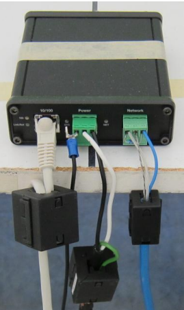
CE Installations
If you are installing the AN-X2 in a location which requires CE, install the following
ferrites or their equivalents on the cables:
Steward 28A2024-0A2 on Ethernet cable close to module, one loop
Steward 28A2024-0A2 on power cable
Steward 28A2025-0A2 on DH+/RIO Cable
Leave a comment
Your email address will not be published. Required fields are marked *