1 Important Notes
1.1 Safety Instructions
General Information
• Do not attempt to install or commission this device without first reading
all documentations provided with the product. Read and understand
these safety instructions and all user documentation prior to working
with the device. If you do not have the user documentation for the
device, contact your responsible Bosch Rexroth sales representative.
Ask for these documents to be sent immediately to the person or
persons responsible for the safe operation of the device.
• If these documentations contain some information you do not
understand, it is absolutely necessary that you ask Bosch Rexroth for
explanation before you start working on or with the devices.
• Only persons who are trained and qualified for the use and operation
of the device may work on this device or within its proximity. The
persons are qualified if they have sufficient knowledge of the
assembly, installation and operation of the equipment as well as an
understanding of all warnings and precautionary measures noted in
this documentation.
• Only trained, instructed and qualified persons are allowed to switch
electrical circuits and devices on and off in accordance with technical
safety regulations, to ground them and to mark them according to the
requirements of safe work practices. These persons must have
adequate safety equipment and be trained in first aid.
• Technical data, connections and operational conditions are specified in
the reference documentations for the product and must be followed at
all times.
• If the products take the form of hardware, then they must remain in
their original state, in other words, no structural changes are permitted.
It is not permitted to decompile software products or alter source
codes.
• Do not mount damaged or faulty products or use them in operation.
• Only use spare parts and accessories approved by Bosch Rexroth.
• Follow all safety regulations and requirements for the specific
application as practiced in the country of use.
• If the device is resold, rented and/or passed on to others in any other
form, these safety instructions must be delivered with the device in the
official language of the user’s country.
• Proper and correct transport, storage, assembly and installation as
well as care in operation and maintenance are prerequisites for
optimal and safe operation of this device. Observe the data contained
in the corresponding product documentations.
WARNING
Improper use of these devices, failure to follow the safety instructions in this
document or tampering with the product, including disabling of safety devices, may
result in material damage, bodily harm, electric shock or even death!
⇒ Observe the following safety instructions!
Contact with Electrical Parts
DANGER
High electrical voltage! Danger to life, electric shock and severe bodily injury!
• Follow general construction and safety regulations when working on power installations.
• Before switching on the device, the equipment grounding conductor must have been
non-detachably connected to all electrical equipment and motors in accordance with the
connection diagram.
The equipment grounding conductor of the electrical equipment and the units must be
non-detachably and permanently connected to the power supply unit at all times. The
leakage current is greater than 3.5 mA.
Over the total length, use copper wire of a cross section of a minimum of 10 mm2
for
this equipment grounding connection!
• Before working with electrical parts with voltage potentials higher than 50 V, the device
must be disconnected from the mains voltage or power supply unit. Provide a safeguard
to prevent reconnection.
• Wait 30 minutes after switching off power to allow capacitors to discharge before
beginning to work. Measure the electric voltage on the capacitors before beginning to
work to make sure that the equipment is safe to touch.
• Never touch the electrical connection points of a component while power is turned on.
• Install the covers and guards provided with the equipment properly before switching the
device on. Before switching the equipment on, cover and safeguard live parts safely to
prevent contact with those parts.
• A residual-current-operated circuit-breaker or r.c.d. cannot be used for electric drives!
Indirect contact must be prevented by other means, for example, by an overcurrent
protective device according to the relevant standards.
Handling and Assembly
CAUTION
Risk of injury by improper handling! Bodily injury by bruising, shearing, cutting, hitting!
• Observe the general construction and safety regulations on handling and assembly.
• Use suitable devices for assembly and transport.
• Avoid jamming and bruising by appropriate measures.
• Always use suitable tools. Use special tools if specified.
• Use lifting equipment and tools in the correct manner.
• If necessary, use suitable protective equipment (for example safety goggles, safety shoes,
safety gloves).
• Do not stand under hanging loads.
• Immediately clean up any spilled liquids because of the danger of skidding.
Dangerous Movements
Dangerous movements can be caused by faulty control of connected
motors. Some common examples are:
• improper or wrong wiring of cable connections
• incorrect operation of the equipment components
• wrong input of parameters before commissioning
• malfunction of sensors, encoders and monitoring devices
• If the device is resold, rented and/or passed on to others in any other
form, these safety instructions must be delivered with the device in the
official language of the user’s country.
• Proper and correct transport, storage, assembly and installation as
well as care in operation and maintenance are prerequisites for
optimal and safe operation of this device. Observe the data contained
in the corresponding product documentations.
Improper use of these devices, failure to follow the safety instructions in this document or tampering with the product, including disabling of safety devices, may result in material damage, bodily harm, electric shock or even death! ⇒ Observe the following safety instructions!
Contact with Electrical Parts
DANGER
High electrical voltage! Danger to life, electric shock and severe bodily injury!
• Follow general construction and safety regulations when working on power installations.
• Before switching on the device, the equipment grounding conductor must have been
non-detachably connected to all electrical equipment and motors in accordance with the
connection diagram.
The equipment grounding conductor of the electrical equipment and the units must be
non-detachably and permanently connected to the power supply unit at all times. The
leakage current is greater than 3.5 mA.
Over the total length, use copper wire of a cross section of a minimum of 10 mm2
for
this equipment grounding connection!
• Before working with electrical parts with voltage potentials higher than 50 V, the device
must be disconnected from the mains voltage or power supply unit. Provide a safeguard
to prevent reconnection.
• Wait 30 minutes after switching off power to allow capacitors to discharge before
beginning to work. Measure the electric voltage on the capacitors before beginning to
work to make sure that the equipment is safe to touch.
• Never touch the electrical connection points of a component while power is turned on.
• Install the covers and guards provided with the equipment properly before switching the
device on. Before switching the equipment on, cover and safeguard live parts safely to
prevent contact with those parts.
• A residual-current-operated circuit-breaker or r.c.d. cannot be used for electric drives!
Indirect contact must be prevented by other means, for example, by an overcurrent
protective device according to the relevant standards.
Handling and Assembly
CAUTION
Risk of injury by improper handling! Bodily injury by bruising, shearing, cutting, hitting!
• Observe the general construction and safety regulations on handling and assembly.
• Use suitable devices for assembly and transport.
• Avoid jamming and bruising by appropriate measures.
• Always use suitable tools. Use special tools if specified.
• Use lifting equipment and tools in the correct manner.
• If necessary, use suitable protective equipment (for example safety goggles, safety shoes,
safety gloves).
• Do not stand under hanging loads.
• Immediately clean up any spilled liquids because of the danger of skidding.
Dangerous Movements
Dangerous movements can be caused by faulty control of connected
motors. Some common examples are:
• improper or wrong wiring of cable connections
• incorrect operation of the equipment components
• wrong input of parameters before commissioning
• malfunction of sensors, encoders and monitoring devices
• defective components
Courtesy
• software or firmware errors
Dangerous movements can occur immediately after equipment is
switched on or even after an unspecified time of trouble-free operation.
The monitoring in the drive components will normally be sufficient to avoid
faulty operation in the connected drives. Regarding personal safety,
especially the danger of bodily harm and material damage, this alone
cannot be relied upon to ensure complete safety. Until the integrated
monitoring functions become effective, it must be assumed in any case
that faulty drive movements will occur. The extent of faulty drive
movements depends upon the type of control and the state of operation.
DANGER
Dangerous movements! Danger to life, risk of injury, severe bodily harm or material
damage!
• For the above reasons, ensure personal safety by means of qualified and tested higherlevel monitoring devices or measures integrated in the installation.
They have to be provided for by the user according to the specific conditions within the
installation and a hazard and fault analysis. The safety regulations applicable for the
installation have to be taken into consideration. Unintended machine motion or other
malfunction is possible if safety devices are disabled, bypassed or not activated.
To avoid accidents, bodily harm and/or material damage:
• Keep free and clear of the machine’s range of motion and moving parts. Possible
measures to prevent people from accidentally entering the machine’s range of motion:
– use safety fences
– use safety guards
– use protective coverings
– install light curtains or light barriers
• Fences and coverings must be strong enough to resist maximum possible momentum.
• Mount the emergency stop switch in the immediate reach of the operator. Verify that the
emergency stop works before startup. Don’t operate the device if the emergency stop is
not working.
• Isolate the drive power connection by means of an emergency stop circuit or use a safety
related starting lockout to prevent unintentional start.
• Make sure that the drives are brought to a safe standstill before accessing or entering the
danger zone.
• Additionally secure vertical axes against falling or dropping after switching off the motor
power by, for example:
– mechanically securing the vertical axes,
– adding an external braking/ arrester/ clamping mechanism or
– ensuring sufficient equilibration of the vertical axes.
• The standard equipment motor brake or an external brake controlled directly by the drive
controller are not sufficient to guarantee personal safety!
• Disconnect electrical power to the equipment using a master switch and secure the switch
against reconnection for:
– maintenance and repair work
– cleaning of equipment
– long periods of discontinued equipment use
• Prevent the operation of high-frequency, remote control and radio equipment near
electronics circuits and supply leads. If the use of such devices cannot be avoided, verify
the system and the installation for possible malfunctions in all possible positions of normal
use before initial startup. If necessary, perform a special electromagnetic compatibility
(EMC) test on the installation.
Magnetic and Electromagnetic Fields
WARNING
Health hazard for persons with heart pacemakers, metal implants and hearing aids in
proximity to electrical equipment!
• Persons with heart pacemakers and metal implants are not permitted to enter following
areas:
– Areas in which electrical equipment and parts are mounted, being operated or
commissioned.
– Areas in which parts of motors with permanent magnets are being stored, repaired or
mounted.
• If it is necessary for somebody with a pacemaker to enter such an area, a doctor must
be consulted prior to doing so. The interference immunity of present or future implanted
heart pacemakers differs greatly, so that no general rules can be given.
• Those with metal implants or metal pieces, as well as with hearing aids must consult a
doctor before they enter the areas described above.
Otherwise health hazards may occur.
Hot Parts
CAUTION
Hot surfaces at motor housings, on drive controllers or chokes! Danger of burns!
• Do not touch surfaces of device housings and chokes in the proximity of heat sources!
Danger of burns!
• Do not touch housing surfaces of motors! Danger of burns!
• According to operating conditions, temperatures can be higher than 60 °C (140 °F)
during or after operation.
• Before accessing motors after having switched them off, let them cool down for a
sufficiently long time. Cooling down can require up to 140 minutes! Roughly estimated,
the time required for cooling down is five times the thermal time constant specified in the
Technical Data.
• Wear safety gloves or do not work at hot surfaces.
• For certain applications, the manufacturer of the end product, machine or installation,
according to the respective safety regulations, has to take measures to avoid injuries
caused by burns in the end application. These measures can be, for example: warnings,
guards (shielding or barrier), technical documentation.
1.2 Appropriate Use
This product may only be used for the applications mentioned in the
reference documentations (see chapter “Reference Documentations”)
and under the described application, ambient and operating conditions.
Identification
2.1 Type Code
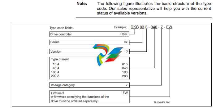
housing dimension; see related dimension sheet also 4) 5) see fig. “Air inlet and outlet of drive controller” 6) observe supply voltage for motor holding brakes 7) find value for control section in project planning manual 8) Suitable for use on a circuit capable of delivering not more than this
SCCR value, 600 V AC or less. The drive series shall be used with
listed AC input line fuses or listed circuit breakers specified in this
documentation.
9) DKC, CZM, BZM: DC bus L+, L-; Mains input L1, L2, L3 10) at PDC_cont 11) class J branch circuit fuse
12) find value for tightening torque in project planning manual, electrical
terminals
13) copper wire; PVC-insulation (conductor temperature 90 °C); Table
13.5.1; Ta ≤ 40 °C
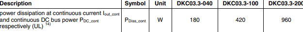
14) plus dissipation of braking resistor
Abb. 3-1: UL ratings and dimensions
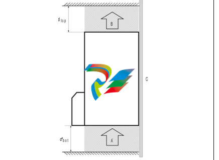
A: air intake
B: air outlet
C: mounting surface in control cabinet
dtop: distance top
dbot: distance bottom
Fig. 3-2: Air intake and air outlet at drive controller
Index
2
24V control voltage supply (+24V and 0V) 5-3
A
Appendix 6-1
Appropriate use 1-4
B
Basic connection of holding brake 5-13
Basic connection of motor power 5-13
Basic connection of motor temperature monitoring 5-13
Bb 5-5
DKC 5-5
BR+, BR- 5-11
C
Connection Choke (DR+, DR-) 5-16
Connection cross section
X1 5-3
X12 5-16
X5 5-7
X6 5-10
Connection Diagram 5-2
Connections 5-1
control cabinet
with multiple-line structure 5-20
Control Cabinet 5-20
Control voltage connections 5-3
Cooling Units 5-20
D
DC Bus Capacitors
discharging 6-1
DC bus connection 5-7
Dimensions 3-1
Discharging of DC Bus Capacitors 6-1
Documentations 4-1
DR+, DR- 5-16
dripping or sprayed water 5-20
Drive enable 5-5
Drive halt 5-5
Drive halt (AH) and Drive enable (RF) 5-4
E
Enclosure 5-20
H
Holding brake (BR+, BR-) 5-11
Holding brakes 5-9
I
Identification 2-1
Important notes 1-1
Installation 5-18
Instructions for Use 5-1
Insulation Monitoring 5-4
M
Mains connections
DKC 5-9
moisture condensation 5-21
Motor connection 5-8
Motor holding brake 5-13
Motor power cables 5-8
Motor temperature monitoring 5-9
Motor temperature monitoring (TM+, TM) 5-10
O
Optional Choke Connection for DKC**.3-200-7 5-15
Overcurrent Protection 5-1
P
Programming module 5-14
Protective conductor connections
XE1, XE2 5-16
R
Ratings 3-1
Ready to operate contact
DKC 5-5
Reference Documentations 4-1
S
Safety instructions 1-1
Setting the Drive Address 5-15
Shield Connections 5-17
Switch S2, S3 5-15
T
Technical data Motor holding brake 5-13
Technical description of connector
X1 5-3
X12 5-15
X5 5-6
X6 5-9
XE1, XE2 5-16
Tightening torque
X12 5-15
X5 5-7
XE1 5-17
XE2 5-17
TM+, TM- 5-10
Touch Guard at Devices 5-19
Type code 2-1
DKC 2-1
Type plates 2-1
U
Use
appropriate 1-4
V
Voltage connection for brakes 5-12
W
Courtesy
Wiring Diagram 5-1
X
X1, Connections for Control voltage 5-3
X12, Optional Choke Connection for DKC**.3-200-7 5-15
X5, DC bus, Motor and Mains Connections 5-6
X6, Motor temperature monitoring 5-9
X7, Connection for Programming module 5-14
XE1, XE2 5-16
XS1, Shield Connection 5-17
XS2, Shield Connection 5-17
XS3, Shield Connection 5-17
Leave a comment
Your email address will not be published. Required fields are marked *