Legal Information
The Schneider Electric brand and any trademarks of Schneider Electric SE and its
subsidiaries referred to in this guide are the property of Schneider Electric SE or its
subsidiaries. All other brands may be trademarks of their respective owners.
This guide and its content are protected under applicable copyright laws and furnished
for informational use only. No part of this guide may be reproduced or transmitted in
any form or by any means (electronic, mechanical, photocopying, recording, or
otherwise), for any purpose, without the prior written permission of Schneider Electric.
Schneider Electric does not grant any right or license for commercial use of the guide
or its content, except for a non-exclusive and personal license to consult it on an “as is”
basis. Schneider Electric products and equipment should be installed, operated,
serviced, and maintained only by qualified personnel.
As standards, specifications, and designs change from time to time, information
contained in this guide may be subject to change without notice.
To the extent permitted by applicable law, no responsibility or liability is assumed by
Schneider Electric and its subsidiaries for any errors or omissions in the informational
content of this material or consequences arising out of or resulting from the use of the
information contained herein.
Overview
The EcoStruxure™ Foxboro™ DCS Field Mounted Intelligent Enclosure provides an
integrated solution designed to be mounted close to instruments in the field to reduce
cables. The Field Mounted Enclosure includes Universal Input/Output (UIO) modules,
power supplies, and Termination Assemblies (TAs) that are pre-installed and tested,
and can be connected to a wide range of field devices. The enclosure supports
Schneider Electric’s Flexible Lean Execution strategy, which shortens project
schedules and reduces the risk of startup delays.
The Field Mounted Intelligent Enclosure is designed to be mounted in the field, and
connects through redundant single mode fiber to the Field Control Processors located
in the Equipment Room Intelligent Enclosure. For more information, refer to
Equipment Room Intelligent Enclosure (PSS 41H-2I30).
The enclosure supports up to 64 standard Universal I/O channels in simplex,
redundant, or simplex and redundant combinations, and optionally accommodates
integration of third party PLCs using simplex or redundant Field Device System
Integration modules supporting Modbus TCP.
A second enclosure can be cascaded from the first enclosure using single mode fiber
or copper cable, saving on communication home run cable to the equipment room.
Field cables, communication cables, and power cables enter the enclosure through
cable glands or a multi-cable transit (optional) located at the bottom of the enclosure.
The channel-to-channel isolated Universal I/O Module supports DI, DO, AI, AO,
HART, NAMUR, Pulse, and 1 ms SOE signal types.
Field cables terminate directly on Termination Assemblies (TAs) with signal
conditioners for optional field signal processing. Refer to Termination Assemblies and
Signal Conditioners, page 8.
Terminals are provided to terminate spare field cable cores and screens. This rugged,
unpainted SS316L stainless steel enclosure can be mounted in harsh environmental
and hazardous areas.
Features
• Protection against harsh environments and hazardous locations:
◦ NEMA® 4X/IP66 rated
◦ Class G3 (harsh) environment
◦ ATEX
• Universal I/O and TAs support any one of these options:
◦ 64 Simplex I/O
◦ 64 Redundant I/O
◦ 48 Simplex and 16 Redundant I/O
• Up to 16 Universal Standard I/O modules (8 x FBM247, 16 x FBM248, or
4 x FBM248 and 6 x FBM247) that support 64 simplex, redundant, or simplex and
redundant I/O Channels using TAs and signal conditioners
• Redundant Field Communication Modules (FCM2F10) for single mode fiber
communication to FCP280
• Up to two Field Device System Integrator Standard modules
(1 x or 2 x FBM232, 2 x FBM233) for Modbus TCP Communication
• Daisy chain from one enclosure to the next to reduce home run cables for
communication and power. Alternatively, the power output used to daisy chain an
enclosure can be used to provide power to a wireless field device access point
installed outside of the enclosure
• Up to two Fieldbus Isolator/Repeator modules for daisy chaining enclosures
using Copper (FBI200) or Fiber Optic cable (FCM2F10)
• 12-port fiber optic patch panel with STconnectors for terminating and distributing
fiber-optic cables for communication to the enclosure and wireless field device
access point
• Document pocket inside front door
• Door stoppers to help prevent the door from swinging or opening too widely
• 120 V AC, 230 V AC system supply
• Supports the Intelligent Commissioning Wizard, which significantly reduces
commissioning effort and shortens the time to plant start-up (see Field Device
Expert for HART Devices Control and I/O (PSS 41S-10FDMHRT))
Environmental Protection
The enclosure provides NEMA4X/IP66 environmental protection, allowing it to be
used in harsh locations.
Thermal Protection
Heat from the equipment mounted within the enclosure is convected naturally and is
dissipated by the exterior surfaces of the enclosure. For operating in ambient
temperatures up to 55° C (131° F), natural convection is supplemented by two
redundant fans that circulate air within the sealed enclosure.
The fans and temperature within the enclosure are monitored by the Enclosure
Monitoring Unit (EMU) that provides a diagnostic alarm on fan deterioration or
enclosure over temperature.
Leave a minimum of 150 mm (6 in) space between adjacent cabinets or a cabinet and
a wall, to allow the flow of air to cool the cabinet.
Cable Entry
Bottom cable entry for power, communication, and field cables is through customer
supplied cable glands that maintain the enclosure protection classification, or optional
factory fitted Multi Cable Transit (MCT).
Modular Baseplate Mounting
The enclosure contains two 8-position standard 200 Series modular baseplates for
Foxboro DCS Fieldbus Modules (FBMs), and two 2-position baseplates for the
FCM2F10s. These are mounted on two vertical DIN rails as shown in Figure 1, page
7. The FBM baseplates include signal connectors for the FBMs, redundant
independent DC power connections, system cable connections, module fieldbus
connections, and time synchronization connections.
For more information on the modular baseplates, see Standard 200 Series
Baseplates (PSS 41H-2SBASPLT).
Field Termination Assemblies
Termination Assemblies (TAs) are installed on the DIN rails mounted at the sides of
the FBM baseplates. The Universal I/O modules are connected to the TAs with preinstalled system cables.
The TAs are supplied with redundant 24 V DC, protected by fuses that are monitored
by the Fuse Monitoring Unit (FMU).
The enclosure is shipped with TAs fitted with passive feed-through signal conditioners
which you can replace with the signal conditioners listed in the section Termination
Assemblies and Signal Conditioners, page 8.
Power Distribution Architecture
The enclosure provides a redundant 24 V power system using two FPS480-24 power
supplies fed by independent sources. Power wiring is routed through the bottom of the
enclosure. The input power connects to the primary and secondary entry terminal
blocks for main and backup power.
Electrical fuses are monitored by the Fuse Monitoring Unit (FMU) and an open fuse
indication from the FMU is wired into the Enclosure Monitoring Unit (EMU) through the
Alarm Distribution Assembly.
Grounding
All enclosure structural elements are integrally grounded by the enclosure design to
meet the appropriate industry regulations and standards. The enclosure is equipped
with two instrument earth bars. It also has a protective connection point at the outside
bottom of the enclosure for customer grounding purposes. Field wiring shields can be
terminated either to the Terminal Assemblies or to the instrument ground bus bar.
Spare signal wires and shields can be terminated either to the Terminal Assemblies or
to the instrument ground bus bar.
Enclosure Diagnostic Alarms
The EMU provides an alarm for power supply failure detection, fuse failure detection
via the FMU, door open, fan deterioration, and enclosure over temperature. The EMU
provides a composite diagnostic alarm from a graduated analog signal that indicates
individual alarms and is prewired to a Universal I/O module channel for indication and
alarm.
Enclosure Security
The enclosure can be physically locked with a customer-supplied padlock to provide
physical security. The enclosure is also fitted with a door open switch that is alarmed
via the Enclosure Monitoring Unit to alert plant personnel.
Enclosure Options
The enclosure can be configured with the following options:
• 120 V AC or 230 V AC supply
• Customer supplied cable glands or factory fitted Multi Cable Transit (MCT)
• Termination Assembly selection for IS, Non-IS, and manufacturer
• 64 simplex UIO points, 64 redundant UIO points, or 48 simplex and 16 redundant
UIO points
• Third party communications through FBM232 modules for simplex Ethernet or
FBM233 modules for redundant Ethernet
• Fiber optic connection to the HDLC Fieldbus using FCM2F10 modules
• Extended twinaxial connection to the HDLC Fieldbus using FBI200 modules
Figure 1 – Interior View of the Enclosure
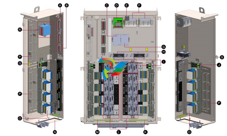
Legend
A 24 V DC Power Distribution Assembly K Instrument Ground Bar
B Alarm Distribution Assembly Terminals L Baseplate 8-Position FBM
C Primary Power Supply M Instrument Ground Bar
D Enclosure Monitoring Unit N Cable Entry (Blank Gland Plate)
E Door Open Switch O Termination Assemblies (Phoenix Contact shown)
F Power Entry Terminal Blocks P Wire Tray, 50 mm x 50 mm x 403 mm (2 in x 2 in x 15.9 in)
G Secondary Power Supply Q Electro Static Discharge Bonding Point
H Fans for internal air circulation R Fiber-Optic Patch Panel
I Baseplate 2-Position FCM S Lock for Customer-Supplied Padlock
J Fuse Monitoring Unit
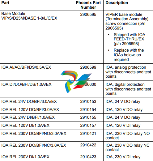
Termination Assemblies and Signal Conditioners
The following tables list the Termination Assemblies and Signal Conditioners
supported. You can select them as required at the time of ordering the enclosure.
Table 1 – Supported Phoenix Termination Assemblies and Signal Conditioners
Leave a comment
Your email address will not be published. Required fields are marked *