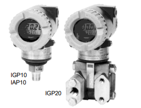
• IGP10 for compact light weight and direct-to-process
mounting (bracket optionally available)
• IGP20, bracket mounted, for lower ranges, more
material options, and vacuum service
• Field-proven silicon strain gauge technology
• Corrosion-resistant epoxy finish
• Accuracy to ± 0.07 % of span
• Ambient temperature effects to ± 0.2 % URL
per 55 °C (100 °F) change
• Intelligent FOXCOM & HART / 4 to 20 mA version
or economical 4 to 20 mA version
• LCD Indicator / Pushbutton Configurator
to set zero, span, display units, etc.
Optional on Digital / 4 to 20 mA version,
Standard on 4 to 20 mA version
These Intelligent, two-wire transmitters provide precise, reliable, measurement of gauge or absolute
pressure, and transmit a 4 to 20 mA output signal
with a superimposed HART/ FOXCOM digital signal for remote configuration and monitoring.
Accuracy (Includes Linearity, Hystersis, and
Repeatability)
Electronics
Version
Configured
Output Signal
Accuracy in %
of Calib. Span
-D & -T Digital
4 to 20 mA
± 0.07
± 0.1
-I 4 to 20 mA ± 0.2
Model Codes IGP10
Ambient Temperature Effect
Total effect for a 55 °C (100 °F) change within Normal Operating Conditions limit is:
Electronics -D, -T: ± 0.2 % of URL
Electronics -I: ± (0.2 % of URL + 0.1 % of span)
For complete specifications, refer to Product Specification
Sheet PSS 2A-1C13 B
Intelligent Direct Connected Gauge Pressure Transmitter IGP10
Electronics Versions and Output Signal
Intelligent; Digital FoxCom and/or 4 to 20 mA dc, Configurable . . . . . . . . . . . . . . -D
Intelligent; Digital HART and 4 to 20 mA . . . . . . . . . . . . . . . . . . . . . . . . . -T
4 to 20 mA Analog Output, Explosionproof and Intrinsically Safe . . . . . . . . . . . . . -I
Structure Code – Process Connection, Sensor, and Fill Fluid
Process Connection Mat’l Sensor Fill Fluid
316L ss Co-Ni-Cr Silicone. . . . . . . . . . . . . . . . . . . . . . . . 20
316L ss Co-Ni-Cr Fluorinert . . . . . . . . . . . . . . . . . . . . . . . 21
316L ss 316L ss Silicone . . . . . . . . . . . . . . . . . . . . . . . 22
316L ss 316L ss Fluorinert. . . . . . . . . . . . . . . . . . . . . . . 23
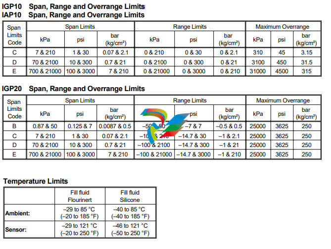
Span Limits – Absolute or Gauge Pressure Units, as Applicable
MPa psi bar or kg/cm²
0.007 and 0.21 1 and 30 0.07 and 2.1…………………………C
0.07 and 2.1 10 and 300 0.7 and 21 …………………………D
0.7 and 21 100 and 3000 7 and 210 ………………………..E
Conduit Connection
1/2 NPT Conduit Connection, Both Sides ……………………………..1
PG 13.5 Conduit Connection, Both Sides (available only with Electrical Safety CodesE&N ………2
Electrical Safety (See Electrical Safety Specifications Section)
CENELEC Certified Intrinsically Safe, ia ………………………………..E
CSA Certified …………………………………………….N
EUROPEAN Ex, N, IIC. Nonsparking ………………………………….C
FM Approved …………………………………………….F
SAA Certified, EEx, d, IIC ……………………………………….A
Options
Mounting Bracket Set
Painted Steel Bracket with Plated Steel Bolts . . . . . . . . . . . . . . . . . . . . . . . . . . . . . . . . . . . . . . . M1
Stainless Steel Bracket with Stainless Steel Bolts . . . . . . . . . . . . . . . . . . . . . . . . . . . . . . . . . . . . . M2
Digital Indicator with Pushbuttons (standard equipment on IGP10-I)
Digital Indicator, Pushbuttons, and Window Cover (for Electr VersionD&T only) . . . . . . . . . . . . . . . . . . . . . -L1
Vent Screw and Block & Bleed Valve
Vent Screw in Process Connection for IGP10/IAP10; or in High Side Process Cover for IGP20. . . . . . . . . . . . . . . V1
Block and Bleed Valve, Carbon Steel . . . . . . . . . . . . . . . . . . . . . . . . . . . . . . . . . . . . . . . . . . . V2
Block and Bleed Valve, 316 ss. . . . . . . . . . . . . . . . . . . . . . . . . . . . . . . . . . . . . . . . . . . . . . . V3
Block and Bleed Valve, 316 ss Body w/Monel Trim (NACE Approved) . . . . . . . . . . . . . . . . . . . . . . . . . . . V4
Conduit Thread Adapters
Hawke-Type 1/2 NPT Cable Gland for use with Conduit Connection Code “1” . . . . . . . . . . . . . . . . . . . . . . . A1
Plastic PG 13.5 Connector for use with Conduit Connection Code “2” (available only with Electrical Safety Codes E & N) . A2
M20 Connector for use with Conduit Connection Code “1” . . . . . . . . . . . . . . . . . . . . . . . . . . . . . . . . . A3
Electronics Housing Features
External Zero Adjustment . . . . . . . . . . . . . . . . . . . . . . . . . . . . . . . . . . . . . . . . . . . . . . . . . Z1
Custody Transfer Lock and Seal . . . . . . . . . . . . . . . . . . . . . . . . . . . . . . . . . . . . . . . . . . . . . . Z2
External Zero Adjustment and Custody Transfer Lock and Seal . . . . . . . . . . . . . . . . . . . . . . . . . . . . . . Z3
Factory Configuration
Digital Output (4 to 20 mA Default if not selected) . . . . . . . . . . . . . . . . . . . . . . . . . . . . . . . . . . . . . C1
Full Factory Configuration (Requires Configuration Form to be filled out) . . . . . . . . . . . . . . . . . . . . . . . . . . C2
Miscellaneous Optional Selections
G 1/2 B Manometer Process Connection (Not Available with Option “-V1”) …………………….G
R 1/2 Process Connection (1/2 NPT to R 1/2 Adapter) ……………………………..R
Five Year Warranty …………………………………………….W
Supplemental Customer Tag (Stainless Steel Tag wired onto Transmitter) …………………….T
Model Codes IGP20 1
Gauge, Abs. and d/p Pressure IGP10 – IGP20 – IAP10
09/1999 CA 2A-1C13 B-(en)
1-3
Intelligent Bracket-Mounted Gauge Pressure Transmitter IGP20
Electronics Versions and Output Signal
Digital, FOXCOM, or 4 to 20 mA dc, Software Selectable ………….D
Digital, HART/4 to 20 mA ………………………..T
4 to 20 mA . . . . . . . . . . . . . . . . . . . . . . . . . . . . . . . . . . . . . I
Structure Code – Process Cover, Sensor Material, and Sensor Fill Fluid
Hi-Side Cover . Sensor Material. . Fill Fluid
Steel …… Co-Ni-Cr…… Silicone . . . . . . . . . . . . . . . . . . . . . 10
Steel …… Co-Ni-Cr…… Fluorinert . . . . . . . . . . . . . . . . . . . . . 11
Steel …… 316L ss …… Silicone. . . . . . . . . . . . . . . . . . . . . . 12
Steel …… 316L ss …… Fluorinert . . . . . . . . . . . . . . . . . . . . . 13
Steel …… Hastelloy C …. Silicone. . . . . . . . . . . . . . . . . . . . . . 16
Steel …… Hastelloy C …. Fluorinert . . . . . . . . . . . . . . . . . . . . . 17
316 ss . . . . . Co-Ni-Cr…… Silicone …… Value Package . . . . . . . 20
316 ss . . . . . Co-Ni-Cr…… Fluorinert . . . . . . . . . . . . . . . . . . . . . 21
316 ss . . . . . 316L ss …… Silicone. . . . . . . . . . . . . . . . . . . . . . 22
316 ss . . . . . 316L ss …… Fluorinert . . . . . . . . . . . . . . . . . . . . . 23
316 ss . . . . . Hastelloy C …. Silicone. . . . . . . . . . . . . . . . . . . . . . 26
316 ss . . . . . Hastelloy C …. Fluorinert . . . . . . . . . . . . . . . . . . . . . 27
Hastelloy C. . . Hastelloy C …. Silicone. . . . . . . . . . . . . . . . . . . . . . 46
Hastelloy C. . . Hastelloy C …. Fluorinert . . . . . . . . . . . . . . . . . . . . . 47
Span Limits (Differential Pressure Units)
kPa . . . . . . psi . . . . . . . . mbar . . . . . . . inH2O…. mmHg
0.87 and 50 . . 0.125 and 7 . . . . 8.7 and 500 . . . . 3.5 and 200 . . 6.5 and 375 . . . . B
MPa . . . . . psi . . . . . . . . bar or kg/cm² . . inH2O…. mmHg
0.007 and 0.21 1 and 30 ….. 0.07 and 2.1 . . . 28 and 840 . . 52 and 1550 ….C
0.07 and 2.1 . . 10 and 300 . . . . 0.7 and 21 . . . . . . . . . . . . . . . . . . . . . . . . D
0.7 and 21 . . . 100 and 3000 . . . 7 and 210 ……………………E
Process Connector Type (Material Same as Process Cover Material)
None, Cover tapped for 1/4 NPT ………………………………0
1/4 NPT . . . . . . . . . . . . . . . . . . . . . . . . . . . . . . . . . . . . . . . . . . . . . . . . 1
1/2 NPT . . . . . . . . . . . . . . . . . . . . . . . . . . . . . . . . . . . . . . . . . . . . . . . . 2
Rc 1/4 . . . . . . . . . . . . . . . . . . . . . . . . . . . . . . . . . . . . . . . . . . . . . . . . . 3
Rc 1/2 . . . . . . . . . . . . . . . . . . . . . . . . . . . . . . . . . . . . . . . . . . . . . . . . . 4
1/2 Schedule 80 Welding Neck……………………………….6
Conduit Connection
1/2 NPT Conduit Connection, Both Sides ……………………………..1
PG 13.5 Conduit Connection, Both Sides (available only with Electrical Safety Codes E & N) ………2
Electrical Safety (See Electrical Safety Specifications Section for Description)
CENELEC Certified Intrinsically Safe, ia …………………………………E
CENELEC Certified Flameproof, d……………………………………D
CSA Certified, ia, d, and n ……………………………………….C
EUROPEAN Ex, N, IIC. Nonsparking ………………………………….N
FM Approved, ia, d, and n ……………………………………….F
SAA Certified, EEx, d, IIC ……………………………………….A
Options
Mounting Bracket Set
Painted Steel Bracket with Plated Steel Bolts . . . . . . . . . . . . . . . . . . . . . . . . . . . . . . . . . . . . . . . M1
Stainless Steel Bracket with Stainless Steel Bolts . . . . . . . . . . . . . . . . . . . . . . . . . . . . . . . . . . . . . M2
Indicator with Internal Pushbuttons (Standard equipment on Electr. Version I)
Digital Indicator, Pushbuttons, and Window Cover, for Electr. VersionD&T only. . . . . . . . . . . . . . . . . . . . . . L1
DIN 19213 Construction, used with Process Connector Code 0 and 316 ss Covers Only(b)
Single Ended Process Cover with M10, B7 Steel Bolting . . . . . . . . . . . . . . . . . . . . . . . . . . . . . . . . . . D1
Double Ended Process Cover with M10, B7 Steel Bolting (Blind Kidney Flange on Back)(c)(d). . . . . . . . . . . . . . . D2
Single Ended Process Cover with 7/16 in, B7 Steel Bolting. . . . . . . . . . . . . . . . . . . . . . . . . . . . . . . . . D3
Double Ended Process Cover with 7/16 in, B7 Steel Bolting (Blind Kidney Flange on Back)(c)(d). . . . . . . . . . . . . . D4
Cleaning and Preparation
Unit Degreased – (Not for Oxygen/Chlorine) (Available only with Structu-re Codes having Silicone). . . . . . . . . . . . . X1
Cleaned and Prepared for Oxygen Service (Available only withStructure Codes having Flourinert
and not available with carbon steel process covers) . . . . . . . . . . . . . . . . . . . . . . . . . . . . . . . . . . . . X2
Cleaned and Prepared for Chlorine Service (Available only with Structure Codes having Flourinert
and not available with carbon steel process covers) (Includes 17-4 ss bolts; do not specify option B2. . . . . . . . . . . . X3
Bolting for Process Covers and Process Connectors
316 ss Bolts and Nuts (Maximum upper range limit pressure 150 bar or 2175 psi) . . . . . . . . . . . . . . . . . . . . . B1
17-4 ss Bolts and Nuts. . . . . . . . . . . . . . . . . . . . . . . . . . . . . . . . . . . . . . . . . . . . . . . . . . . B2
Gauge, Abs. and d/p Pressure IGP10 – IGP20 – IAP10
CA 2A-1C13 B-(en) 09/1999
1-4
Options (continued)
Conduit Thread Adapters
Hawke-Type 1/2 NPT Cable Gland (for use with 1/2 NPT Conduit Connection Code 1) . . . . . . . . . . . . . . . . . . A1
Plastic PG 13.5 Connector (for use with PG 13.5 Conduit Connection Code 2)
(available only with Electrical Safety Codes E & N). . . . . . . . . . . . . . . . . . . . . . . . . . . . . . . . . . . . . A2
M20 Connector (for use with 1/2 NPT Conduit Connection Code 1) . . . . . . . . . . . . . . . . . . . . . . . . . . . . A3
Electronics Housing Features
External Zero Adjustment . . . . . . . . . . . . . . . . . . . . . . . . . . . . . . . . . . . . . . . . . . . . . . . . . Z1
Custody Transfer Lock and Seal . . . . . . . . . . . . . . . . . . . . . . . . . . . . . . . . . . . . . . . . . . . . . . Z2
External Zero Adjustment and Custody Transfer Lock and Seal . . . . . . . . . . . . . . . . . . . . . . . . . . . . . . Z3
Factory Configuration
Digital Output (4 to 20 mA Default if not selected) (Electr. Version D only) . . . . . . . . . . . . . . . . . . . . . . . . . C1
Full Factory Configuration (Requires Configuration Form) . . . . . . . . . . . . . . . . . . . . . . . . . . . . . . . . . C2
Ermeto Connectors
Steel, Connecting 6 mm Tubing to 1/4 NPT Process Connector . . . . . . . . . . . . . . . . . . . . . . . . . . . . . . E1
Steel, Connecting 12 mm Tubing to 1/2 NPT Process Connector . . . . . . . . . . . . . . . . . . . . . . . . . . . . . E2
316 ss, Connecting 6 mm Tubing to 1/4 NPT Process Connector . . . . . . . . . . . . . . . . . . . . . . . . . . . . . E3
316 ss, Connecting 12 mm Tubing to 1/2 NPT Process Connector. . . . . . . . . . . . . . . . . . . . . . . . . . . . . E4
Miscellaneous Optional Selections
Vent Screw In Side of Process Cover……………………………………..V
Five Year Warranty …………………………………………….W
Supplemental Customer Tag …………………………………………T
(a) Refer to PSS 2A-1Z9 E for option descriptions, and for additional optional features and accessories not listed in Model Code.
(b) See Functional Specifications section for pressure deratings when certain DIN 19213 versions are specified.
(c) Temperature limits derated to 0 and 60°C (32 and 140°F).
(d) Mounting Set option is not available.
Leave a comment
Your email address will not be published. Required fields are marked *