Important Information
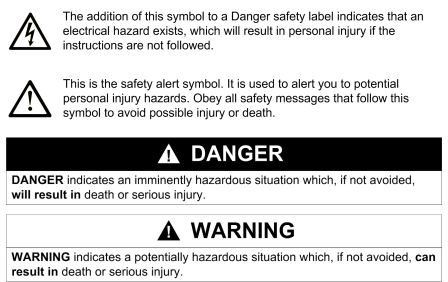
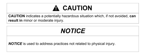
NOTICE
Read these instructions carefully, and look at the equipment to become familiar with
the device before trying to install, operate, or maintain it. The following special
messages may appear throughout this documentation or on the equipment to warn
of potential hazards or to call attention to information that clarifies or simplifies a
procedure.
PLEASE NOTE
Electrical equipment should be installed, operated, serviced, and maintained only by
qualified personnel. No responsibility is assumed by Schneider Electric for any
consequences arising out of the use of this material.
A qualified person is one who has skills and knowledge related to the construction
and operation of electrical equipment and its installation, and has received safety
training to recognize and avoid the hazards involved.
About the Book
At a Glance
Document Scope
This manual is a reference guide for the hardware of the Quantum automation
system.
Validity Note
The data and illustrations found in this book are not binding. We reserve the right to
modify our products in line with our policy of continuous product development. The
information in this document is subject to change without notice and should not be
construed as a commitment by Schneider Electric.
Product Related Information
Schneider Electric assumes no responsibility for any errors that may appear in this
document. If you have any suggestions for improvements or amendments or have
found errors in this publication, please notify us.
No part of this document may be reproduced in any form or by any means, electronic
or mechanical, including photocopying, without express written permission of
Schneider Electric.
All pertinent state, regional, and local safety regulations must be observed when
installing and using this product. For reasons of safety and to ensure compliance
with documented system data, only the manufacturer should perform repairs to
components.
When controllers are used for applications with technical safety requirements,
please follow the relevant instructions.
Failure to use Schneider Electric software or approved software with our hardware
products may result in improper operating results.
Failure to observe this product related warning can result in injury or equipment
damage
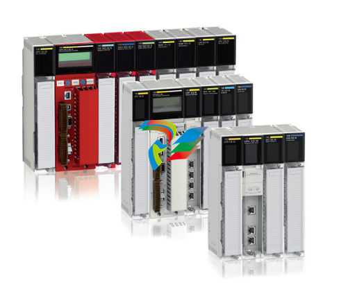
Modicon Quantum Automation
System Overview
Introduction
This chapter provides an overview of the Modicon Quantum Automation System,
which includes Modicon Quantum software support.
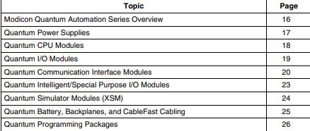
What Is in This Chapter?
This chapter contains the following topics:
Quantum Power Supplies
Overview
Quantum power supplies are used to supply system power to all modules inserted
into the backplane, including:
Quantum CPU modules
Quantum Interface modules
Quantum I/O modules
Depending upon the system configuration, the option exists of using the power
supply in three different modes.
Power Supply Modes
The following table shows the power supply modes.
Power Supply Type Usage
Standalone For 3 A, 8 A or 11 A configurations that do not require fault
tolerant or redundant capabilities.
Standalone Summable For configurations consuming more than the rated current of one
supply, two summing power supplies can be installed in the
same backplane.
Redundant For configurations requiring power for uninterrupted system
operation. Two redundant power supplies are required for
redundancy
CAUTION
System Safety
Exercise caution when considering a combination of power supplies in a
backplane. Use only like power supplies with the exceptions noted in System
Design Considerations for Quantum Power Supplies, page 797.
Failure to follow these instructions can result in injury or equipment damage
Quantum CPU Modules
Overview
The Quantum CPU is a module residing on the Quantum local I/O backplane. The
CPU is a digitally operating electronic system, which uses a programmable memory
for the internal storage of user instructions. These instructions are used to
implement specific functions such as:
Logic
Process sequencing
Timing
Coupling
Arithmetic
These instructions allow control through digital and analog outputs, for various types
of machines and processes.
The Quantum CPU serves as a bus master controlling the local, remote, and
distributed I/O of the Quantum system.
Quantum I/O Modules
Overview
Quantum I/O modules are electrical signal converters that convert signals to and
from field devices to a signal level and format, which can be processed by the CPU,
such as:
Limit switches
Proximity switches
Temperature sensors
Solenoids
Valve actuators
All I/O modules are optically isolated to the bus, ensuring safe and trouble-free
operation. All I/O modules are also software configurable.
Quantum Communication Interface Modules
Overview
Nine types of communication interface modules are available and presented in the
table below, and are described in the following text.
Network Interface Modules
The following table shows the communication interface modules.
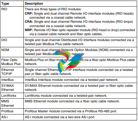
RIO Modules (CRP/CRA/NRP)
Quantum RIO head and drop modules use a S908-based networking I/O
configuration. Communication is done via single or dual coaxial cabling up to 15,000
feet away. This configuration supports a mix of the following product lines:
SY/MAX
200 Series
500 Series
800 Series
Quantum I/O
When Quantum RIO is required, the Quantum controller may support up to 31 RIO
drops. In an RIO configuration, an RIO head module is connected with coaxial cable
to RIO drop modules at each remote drop.
Quantum NRP modules provide extended communication capabilities and noise
immunity for the Quantum RIO network with fiber optic media.
DIO Module (CRA)
Quantum DIO is implemented over a Modbus Plus network. The CPU or NOMs
module may be the network head via their Modbus Plus ports.
Quantum DIO Modbus Plus drop adaptors are specifically designed to link Quantum
I/O modules to the head via twisted pair shielded cable (Modbus Plus). The DIO
drop modules also provide the I/O with power (maximum 3A) from a 24 Vdc or a
115/230 Vac source. Each DIO network supports up to 63 distributed drops using
repeaters.
Network Option Module (NOM)
Quantum NOM modules provide extended communication capabilities for the
Quantum system within a Modbus Plus configuration.
Modbus Plus on Fiber Module (NOM)
Quantum Modbus Plus on Fiber modules provides connectivity to Modbus Plus
nodes by fiber cable without fiber optic repeaters, and allows the creation of a pure
fiber optic network or a mixed fiber optic/twisted-pair network (with the use of a
490NRP254 Fiber Optic Repeater).
Ethernet TCP/IP (NOE) Modules
Quantum Ethernet TCP/IP modules make it possible for a Quantum controller to
communicate with devices on an Ethernet network using TCP/IP – the de facto
standard protocol. An Ethernet module may be inserted into an existing Quantum
system and connected to existing Ethernet networks via fiber optic or twisted pair
cabling
SY/MAX Ethernet Modules (NOE)
Quantum-SY/MAX-Ethernet modules are Quantum CPU network option modules
that can be placed in a Quantum backplane to connect Quantum controllers to
SY/MAX devices and applications.
MMS-Ethernet Modules (NOE)
Quantum-MMS-Ethernet modules are Quantum CPU network option modules that
can be placed in a Quantum backplane to connect Quantum controllers to MMS
devices and applications.
InterBus Interface Module (NOA)
The Quantum InterBus is the interface module to the InterBus bus. The InterBus bus
is a fieldbus network designed for I/O blocks and intelligent devices used in
manufacturing. It offers a master/slave topology that permits deterministic I/O
servicing over it’s 13 km twisted pair network.
LonWorks Modules (NOL)
Quantum NOL modules provide connectivity between a Quantum controller and a
LonWorks network, based on Echelon’s LonWorks technology. The NOL module is
offered in three models for different transceiver types, and supports three twistedpair media types with different network topologies or data transfer speeds.
Profibus Interface Module (CRP)
Quantum Profibus module is the interface module to Profibus-DP networks. The
interface modules use Type A, shielded twisted pair to join inline connectors, with or
without service ports and bus terminators.
AS-i Interface Module
Quantum AS-i modules provide connectivity between a Quantum controller and ASi networks. AS-i bus cable is an unshielded flat two-wire link on which
communication and power are transmitted to connected devices. The media
insulation is self-healing to accommodate junction block removal.
Leave a comment
Your email address will not be published. Required fields are marked *