1 General Information
1.1 About this manual
The manual is part of the product and contains important information about installation,
startup, operation and service. The manual is written for everyone installing, starting up
or servicing this product.
The manual must be accessible and legible. Make sure that persons responsible for the
system and its operation, as well as persons who work independently on the unit, have
read through the manual carefully and understood it. If you are unclear about any of the
information in this documentation, or if you require further information, contact SEWEURODRIVE.
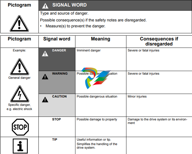
1.2 Structure of the safety notes
The safety notes in this manual are designed as follows:
1.3 Rights to claim under limited warranty
A requirement of fault-free operation and fulfillment of any rights to claim under limited
warranty is that you adhere to the information in the MOVITRAC® B documentation.
Therefore, read the operating instructions before you start working with the unit.
Make sure that the documentation is available to persons responsible for the system and
its operation as well as to persons who work independently on the unit. You must also
ensure that the documentation is legible.
1.4 Exclusion of liability
You must comply with the information contained in the MOVITRAC® B documentation
to ensure safe operation of MOVITRAC® B and to achieve the specified product characteristics and performance requirements. SEW-EURODRIVE assumes no liability for
injury to persons or damage to equipment or property resulting from non-observance of
the documentation. In such cases, any liability for defects is excluded.
1.5 Copyright notice
© 2009 – SEW-EURODRIVE. All rights reserved.
Unauthorized duplication, modification, distribution or any other use of the whole or any
part of this documentation is strictly prohibited.
1.6 Content of this publication
This publication contains conditions and amendments related to MOVITRAC® B in
safety-oriented applications.
The system comprises a frequency inverter with asynchronous motor and safety-tested
external disconnecting device.
1.7 Other applicable publications
This document supplements the MOVITRAC® B operating instructions and limits the
application notes according to the following information.
It can only be used in conjunction with the following publications:
• The MOVITRAC® B operating instructions must always be observed.
For permitted connection variants, refer to chapter “Connection variants” (see page 17).
Safety Concept
• In case of danger, any potential risk related to a machine must be eliminated as
quickly as possible. Standstill with restart prevention is generally the safe condition
for preventing dangerous movements.
• MOVITRAC® B is characterized by the optional connection of X17 to an external failsafe, prototype tested safety relay. The safety relay disconnects all active elements
(disconnection of the safety oriented 24 V power supply of the output stage control)
that generate the pulse trains to the power output stage (IGBT) when a connected
control device (E-STOP button with latching function) is activated.
• Disconnecting the 24 V voltage supply at connector X17 ensures that the supply
voltages required for operating the frequency inverter and consequently for
generating a rotating field of pulse patterns (which allow the generation of a rotating
field) are safely interrupted, preventing automatic restart.
• Instead of separating the drive galvanically from the power supply using contactors
or switches, the disconnection procedure described here prevents the power
semiconductors in the frequency inverter from being activated, thus ensuring safe
disconnection. This process disconnects the rotating field generation for the
respective motor. The individual motor cannot develop any torque in this state even
though the mains voltage is still present.
• The requirements for the safety control are clearly defined in the following sections
and must be observed.
Using a suitable external circuit via a safety control
– with approval to at least EN 954-1 category 3
enables operation of the MOVITRAC® B frequency inverter with safe disconnection to stop category 0 or 1 according to EN 60204-1, fail-safe protection against
restart according to EN 1037 and fulfillment of safety category 3 to EN 954-1.
Using a suitable external circuit via a safety control
– with approval for EN ISO 13849-1, performance level “d”
enables operation of the MOVITRAC® B frequency inverter with safe disconnection according to stop category 0 or 1 to EN 60204-1, fail-safe protection against
restart according to EN 1037 and fulfillment of performance level “d” to EN ISO
13849-1.
Limitations
• Important: The safety concept is only suitable for performing mechanical work
on system/machine components.
• Important: A system/machine-specific risk analysis must always be carried out
by the system/machine manufacturer and taken into account for the use of the
MOVITRAC® B frequency inverter.
• Danger of fatal injury: When the safety-oriented 24 V voltage supply is
disconnected, the mains supply voltage is still present at the frequency
inverter DC link.
• Danger of fatal injury: When the 24 V voltage supply is disconnected, the DC
link voltage is still present at the MOVITRAC® B frequency inverter.
• Important: If work is carried out on the electrical section of the drive system,
the DC link voltage must be disconnected.
Representation of the “Safety concept for MOVITRAC® B / control unit”
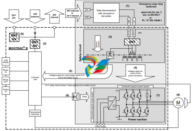
[1] Safety relay (external)
[2] Low-voltage switch-mode power supply
[3] Safety switched-mode power supply (SNT)
[4] Voltage supply for controlling the power transistors
[5] Feedback to the central processing unit: Voltage supply for output stage control OK (not in safety circuit)
[6] Pulse width modulated signals for output stage
[7] Power section
[8] Motor
[9] High-voltage switch-mode power supply
Representation of the “Safety concept for MOVITRAC® B / size 0”
Safety-Relevant Conditions
The following conditions are mandatory for the installation and operation of
MOVITRAC® B in applications with safe disconnection of the drive in accordance with
category 0 or 1 of EN 60204-1 and fail-safe protection against restart according to
EN 1037, and conformance with safety category 3 of EN 954-1 or performance level “d”
of EN ISO 13849-1. The conditions are divided into the following sections:
• Approved devices
• Installation requirements
• Requirements for external safety relays
• Startup requirements
• Operation requirements
3.1 Information on the stop categories
• Stop category 0 means that the safety 24 V voltage supply can be disconnected
independent of the setpoints.
• Observe the following procedure for stop category 1:
– Decelerate the drive using an appropriate brake ramp specified by the setpoint.
– Disconnect the safety-oriented 24 V voltage supply
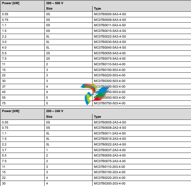
3.2 Approved devices
The following frequency inverters are permitted for applications with safe disconnection
according to stop category 0 or 1 of EN 60204-1, fail-safe protection against restart
according to EN 1037 and compliance with safety category 3 according to EN 954-1 or
performance level “d” according to EN ISO 13489-1.
3.2.1 MOVITRAC® B for AC 3 × 380 – 500 V / 200 – 240 V supply voltage
3.2.2 Hazard caused by coasting drive
Note that if the drive does not have a mechanical brake, or if the brake is defective, the
drive may coast to a halt.
Note: If coasting to a halt results in application-dependent hazards, take
additional protective measures (e.g. movable covers with closure), which cover
the hazardeous area until persons are no longer in danger.
The additional protective covers must be designed and integrated in such a way that
they meet the safety category required for the machine.
After activating the stop command, access to the machine must remain blocked until the
drive has reached standstill, or the access time has to be determined to ensure that an
adequate safety distance is maintained.
3.3 Installation requirements
Note the following instructions for applications of MOVITRAC® B with safe disconnection of the drive according to stop category 0 or 1 according to EN 60204-1 and fail-safe
protection against restart according to EN 954-1 safety category 3 or performance level
“d” according to EN ISO 13849-1.
• The line between the safety control system (or the safety-oriented tripping device)
and MOVITRAC® B terminal X17 is designated as the safety-oriented 24 V voltage
supply.
• Power lines and the safety-oriented 24 V supply voltage must be installed in separate
cable ducts.
• The safety-oriented 24 V supply voltage must be routed according to EMC guidelines
and as follows:
– Outside an electrical installation space: Shielded cables must be routed
permanently (fixed) and protected against external damage, or other equivalent
measures.
– Individual conductors can be routed inside an electrical installation space.
Observe the respective regulations governing the application.
• It must be ensured that parasitic voltages cannot be generated in the safety-oriented
24 V supply voltage.
• The total cable length between the safety control system (e.g. safety relay) and
MOVITRAC® B is limited to a maximum length of 100 m for EMC reasons.
• The switching capacity of the safety relay and the maximum permissible voltage drop
on the 24 V supply cable must be observed during disconnection of group drives.
• Only use terminal connections (terminal blocks) that meet EN 60204-1 and prevent
short-circuits.
• Observe the notes in the “MOVITRAC® B” operating instructions on EMC compliant
cabling. It is essential that you apply the shielding at both ends on the housing.
• Only use power supplies with safe isolation (SELV/PELV) according to VDE010.
According to EN 60950-1, the voltage between the outputs or between any output
and a ground part must not exceed DC 60 V voltage for longer than 0.2 s after only
one fault. The maximum DC voltage must be 120 V.
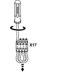
• You must remove the jumpers at X17:1 to X17:4 (see following figure) for use in
applications with safe disconnection of the drive according to stop category 0 or 1 in
accordance with EN 60204-1 and fail-safe protection against restart according to
EN 954-1 safety category 3 or performance level “d” according to EN ISO 13849-1.
• The shielded lines of the safety-oriented 24 V voltage supply (terminal X17) must be
clamped under the signaling electronics shield clamp.
• You must observe the technical data of MOVITRAC® B (see MOVITRAC® B
operating instructions).
Removing jumpers
Requirements on external safety relays
• If the requirements of the standard EN 954-1 are to be met, at least one approval for
safety category 3 according to EN 954-1 must be available.
• If the requirements of the standard EN ISO 13849-1 are to be met, at least one
approval for performance level “d” according to EN ISO 13849-1 must be available.
• If the DC 24 V voltage supply is safely disconnected at the positive pole only, no test
pulses must be applied to this pole in disconnected condition.
• Bipolar disconnection of the DC 24 V supply is permitted.
• The values specified for the safety relays must be adhered to when designing the
circuit.
• The switching capacity of the safety relays must correspond at least to the maximum
permitted limited output current of the DC 24 V voltage supply. Observe the
manufacturer’s instructions for the safety relays concerning the permitted
contact loads and fusing that may be required for the safety contacts. Unless
specified otherwise, the contacts must be protected with 0.6 times the nominal
value of the maximum contact rating specified by the manufacturer.
• The controller must be designed and connected in such a way that resetting the
control device itself will not lead to a restart. A restart may only be carried out after
an additional reset of the controller.
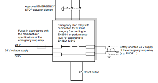
3.4.1 “Safety relay” sample circuit
The following figure shows the basic connection of an external safety relay (according
to the before mentioned requirements) to MOVITRAC® B.
The information in the respective manufacturer’s data sheets must be observed for
connection.
1-pole disconnection of the 24 V supply voltage:
3.5 Startup requirements
• Startup must be documented and the functionality of the safety functions must be
demonstrated.
• Startup checks of the disconnecting device and the correct wiring must be performed
and documented for MOVITRAC® B with safe disconnection of the drive according
to stop category 0 or 1 of EN 60204-1, fail-safe protection against restart according
to EN 1037 and compliance with safety category 3 according to EN 954-1 or
performance level “d” according to EN ISO 13849-1.
• At startup, the safety-related 24 V control voltage must be included in the functional
test.
3.6 Operation requirements
• Operation is only allowed within the limits specified in the data sheets. This applies
both to the external safety relay as well as MOVITRAC® B.
• The safety functions must be checked at regular intervals to ensure proper
functioning. The period of time between the tests should be specified in accordance
with the risk analysis.
Connection Variants
Refer to the publication “Safe Disconnection for MOVITRAC® B – Applications” for
examples of approved connection variants of units listed in the section “Approved Units”
for safe disconnection of the drive according to stop category 0 or 1 of EN 60204-1 and
fail-safe protection against restart according to EN 1037 and fulfillment of the safety
category according to EN 954-1 or performance level “d” of EN ISO 13849-1. The
publication “Safe Disconnection for MOVITRAC® B – Applications” is constantly being
supplemented by possible applications. The publication includes checklists, which offer
additional assistance in project planning and installation as well as operating
MOVITRAC® B drives in safety-oriented applications. It is essential that you comply with
the publications listed in the section “Safety and warning instructions” for all the
connection variants listed in the publication “Safe Disconnection for MOVITRAC® B –
Applications”.
4.1 Disconnection of single drives
4.1.1 Requirements
The requirements of the manufacturers of safety relays (such as protecting the output
contacts against welding) or other safety components must be strictly observed. In
addition, the basic requirements described in the manual “Safe Disconnection for
MOVITRAC® B – Conditions” apply for cable routing.
For reasons of EMC, the length of the cable between connection X17 on
MOVITRAC® B and the safety components (e.g. safety relay) is limited to a maximum
of 100 m. Other instructions by the manufacturer on the use of safety relays for specific
applications must also be observed.
4.1.2 Internal 24 V supply, stop category 0
4.2 Disconnection of group drives
4.2.1 Requirements
For group drives, the 24 V supply of several MOVITRAC® B units can be made available
by a single safety relay. The maximum possible number of units (n units) results from
the maximum permitted contact load of the safety relay and the maximum permitted
voltage drop of the DC supply for MOVITRAC® B units.
Other requirements of the safety relay manufacturer (such as protecting the output
contacts against welding) must be strictly observed. In addition, the basic requirements
described in the manual “Safe Disconnection for MOVITRAC® B – Conditions” apply for
cable routing.
For reasons of EMC, the length of the cable between connection X17 (MOVITRAC® B)
and the safety components (e.g. safety relay) is limited to a maximum of 100 m.
Other instructions by the manufacturer on the safety relay used in the specific
application must also be observed.
Determining the maximum number of MOVITRAC® B drives for disconnection of group drives
The number (n units) of MOVITRAC® B units that can be connected to a group drive with
safe disconnection is limited by the following points:
1. Switching capacity of the safety relay.
A fuse must be connected in front of the safety contacts according to the
specifications of the safety relay manufacturer to prevent the contacts from sticking
or welding.
The project planner is responsible for ensuring that the specifications on the
switching capacity according to EN 60947-4-1, 02/1 and EN 60947-5-1, 11/97 as well
as on contact fuse protection given in the operating instructions of the safety relay
manufacturer are strictly observed.
2. Maximum permitted voltage drop in the 24 V power supply cable.
Values concerning cable lengths and permitted voltage drops must be observed
during project planning for group drives.
3. Maximum cable cross section of 1×1.5 mm2 or 2×0.75 mm2.
A calculation based on the technical data of MOVITRAC® B must be performed
separately for each group drive application.
Leave a comment
Your email address will not be published. Required fields are marked *