Power supply for 2-wires types of transducers and
signal conditioners
] μA to mV conversion for long distance signal
transmission
] Certified for use with measuring chains in potentially
explosive atmospheres
] Galvanic separation voltage: 4 kVRMS
] High rejection of frame voltage
] DIN-Rail mounting
The versatile GSI 124 galvanic separation unit replaces
its predecessors: GSI 122, GSI 123 and GSI 130. The
GSI 124 is for use with piezo-electric transducers with
integrated electronics (eg. CE XXX), piezo-electric transducer signal conditioners (eg. IPC XXX) and proximity
probe signal conditioners (eg. IQS 4XX series).
The unit is intended for use in 2-wire transmission systems at high frequencies. More generally, it may be used
to supply any electronic system having a consumption of
less than 20 mA.
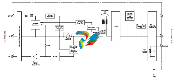
The GSI 124 avoids the use of Zener barriers for Exi
applications. It allows the transmission of AC signals
over long distances. The unit rejects a large amount of
the RMS voltage of ground noise and avoids AC noise
pickup which can occur between the sensor case and
the poles of the sensor.
BLOCK DIAGRAM
Environmental characteristics
General
Temperature
• Operating : 0°C to 70°C
• Storage : -20°C to +85°C
Vibration (according to IEC68.2.6) : 5Hz to 35 Hz, 90 minutes/axis
0.15 mm peak below resonance frequency, 1 g peak above
Humidity (according to IEC68.2.30)
• Operating : Up to 90%, non-condensing
• Storage : Up to 95%, non-condensing
Shock
(according to IEC68.2.27)
: Half-sine, 6 g peak, 11 ms, 3 shocks/axis
Induced signal susceptibility
(according to IEC61000-4-4/5)
: Performance criteria B
RF susceptibility
(according to IEC61000-4-3)
: Performance criteria A
RF Emissions
(according to IEC61000-4-3)
• Limits at 1 m : 30 MHz to 230 MHz < 60 dBμV/m (quasi-peak)
: 230 MHz to 1000 MHz < 67 dBμV/m (quasi-peak)
Electrostatic discharge
(according to IEC61000-4-2)
: Performance criteria B
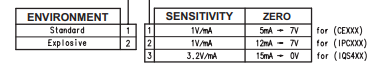
Explosive atmospheres (ordering option A2)
• EC type examination certificate : LCIE 05 ATEX 6033 X
II (2) G (outside potentially explosive zone) [EEx ib] IIC
For specific parameters of the mode of protection concerned and special conditions for safe use, please refer to
the “EC type examination certificate” that is available from Vibro-Meter SA on demand.
• cCSAus certificate : cCSAus certificate 1699234
Class I, Div 1, Groups A,B,C,D [Ex ia]
Electrical Characteristics
Power supply (user side)
Supply voltage
• With IPC XXX and CE XXX : 20 VDC to 30 VDC
• With IQS 4XX : 22.5 VDC to 30 VDC
Current consumption (with 24 VDC supply)
• Without load on transducer side : ≤ 20 mA
• With 12 mA on transducer side : ≤ 50 mA
• With 20 mA on transducer side : ≤ 70 mA
• With a short-circuit on transducer side : ≤ 70 mA
Output signal (monitor side)
Voltage output dynamic range (with 10 kΩ load) : ≥ 2 VDC
≤ U supply – 2.5 VDC
Output impedance : ≤ 1 Ω protected against short-circuits
Power supply voltage rejection ratio
• Standard (ordering option A1) : ≥ 55 dB at 10 Hz to 400 Hz
: ≥ 35 dB at 400 Hz to 100 kHz
• Explosive (ordering option A2) : ≥ 55 dB at 10 Hz to 400 Hz
: ≥ 35 dB at 400 Hz to 5 kHz
: ≥ 28 dB at 5 kHz to 100 kHz
Thermal output signal offset drift (0 … 70°C) : ≤ 4 mV/°C (200 ppm/°C)
Thermal output signal sensibility drift (0 … 70°C) : ≤ 100 ppm/°C
AC output signal residual noise
• Band width: 0 to 1 kHz : ≤ 2 μVRMS/√Hz
• Band width: >1 kHz : ≤ 4 μVRMS/√Hz
Input signal (transducer side)
Output supply voltage on 2-wires transmitting line : 21.5 VDC ± 2.5 VDC (without load)
Impedance : ≤ 90 Ω
Current dynamic range on 2-wires transmitting line : 0 mA to 20 mA
Short-circuit current limit on 2-wires transmitting line : ≤ 30 mA
Maximal load capacitance
• Standard : Cmax = 200 nF
• Explosive atmospheres : Cmax = 99 nF
Maximal load inductance
• Standard : Lmax = 30 mH
• Explosive atmospheres : Lmax = 25 mH
Transfer Characteristics (ordering option B)
Sensitivity
• IPC XXX and CE XXX : 1 V/mA ± 10 mV/mA
• IQS 4XX : 3.2 V/mA ± 32 mV/mA
Output offset voltage (zero)
• IPC XXX (12 mADC on transmitting line) : 7 VDC ± 100 mVDC
• CE XXX (5 mADC on transmitting line) : 7 VDC ± 100 mVDC
• IQS 4XX (17.5 mADC on transmitting line) : 8 VDC ± 100 mVDC
Band width
IPC XXX and CE XXX (ordering option B1 and B2)
• Frequency band with a transfer inside ± 0.5 dB : DC to 20 kHz
• Typical frequency cut at -3 dB : 30 kHz
IQS 4XX (ordering option B3)
• Frequency band with a transfer inside ± 0.5 dB : DC to 10 kHz
• Typical frequency cut at -3 dB : 25 kHz
Linearity : < 0.2%
Galvanic separation voltage 4 kVRMS
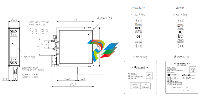
Physical Characteristics
Dimensions : See mechanical drawing
Weight : 130 gr
Electronic housing material : Polyamide (PA 6.6) green
Electrical connections : With terminal screw – see m
o order please specify:
Type
Designation
Ordering number
: GSI 124
: Galvanic separation unit
: 244-124-000-02X-A -B
In this publication, a dot (.) is used as the decimal separator and thousands are separated by spaces. Example : 12 345.678 90. Although care has been
taken to assure the accuracy of the data presented in this publication, we do not assume liability for errors or omissions. We reserve the right to alter any
part of this publication without prior notice.
Leave a comment
Your email address will not be published. Required fields are marked *